The importance of making correct calculations when designing a sewer system
Wastewater is not just a flowing liquid of a homogeneous structure. Sewage includes impurities of various fractions and weights. The polydisperse substance, which is wastewater, also contains colloids and suspensions. The speed of movement of sewage may change periodically. If liquid inclusions move faster, then heavy impurities in the form of sand, slag, etc. more often settle on the walls of the pipes, forming growths and blockages. As a result, the collector becomes clogged. To prevent this from happening, hydraulic calculations of sewer networks are carried out at the system design stage.
To calculate all parameters, the estimated volume of wastewater is taken as the initial data.
Basic calculation parameters
First of all, the specialist is interested in the minimum slope of the pipeline, although, of course, this is not the only aspect that affects the overall design of the system. The slope also dictates the installation features of the sewer system:
- at what depth the pipes will be laid;
- what is the pipeline cross-section for each segment;
- how plumbing elements will be placed.
Basic performance properties:
- at what speed does wastewater move;
- filling the pipeline.
Main types of payments
When performing calculations, data from SNiP 2.04.03-85 “Sewerage. External networks and structures”, as well as recommendations from SP 40-102-2000 “Design and installation of pipelines for water supply and sewerage systems made of polymer materials. General requirements".
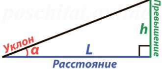
Slope of sewerage pipeline
Recommended slope
The slope is responsible for the free-flow operation of the system and the unhindered discharge of wastewater into the receiver. The SNiP tables show the recommended minimum slopes for each pipe diameter:
- cross section 110 mm - 1 cm for each linear meter of the collector;
- diameter 160 mm - 0.8 cm per meter;
- cross section 220 mm - 0.7 cm per meter of collector length.
For the internal part of the communication, a slope of 1.5-2 cm is maintained for each linear meter.
If there is a need to calculate the slope of the collector using the formula, use the following: d x coefficient, where d is the cross-section of the pipeline, and the coefficient corresponds to the following values:
- 160 — 0,6;
- 220 — 0,7;
- 500 mm - 1;
- 600-800 — 1,1;
- 1000-1200 mm - 1.3.
The slope is made towards the central highway or yard septic tank/cesspool.
Calculation of pipe cross-sections
To lay pipes of the required diameter, you can use the SNiP data. The recommended values look like this:
- the internal part of the sewer from all plumbing fixtures - 50 mm;
- toilet pipe - 110 mm;
- public riser - 110-160 mm;
- external part of the sewerage system - 160-220 mm (for the private sector and multi-apartment residential building);
- central highway and industrial enterprises - from 500 mm.
With the correct cross-section of the collector, the fullness of the pipe will be approximately 0.3-0.5 of its total diameter.
Calculation of reservoir filling
The fullness of the pipe is calculated using the formula: Y= h/d. Here the value h is the maximum liquid level in the system, d is the internal cross-section of the collector. Normally, the result should range from 0.3 to 0.6.
An example of calculating the filling level of a sewer pipe in the private sector: the initial data is taken as the filling level of the collector within 60 mm, while the cross-section of the pipe is 110 mm. According to the above formula, 60/110 equals 0.55. The value is normal.
Calculation of pipe capacity
At the time of designing the system, the throughput of the pipeline must be calculated - the estimated wastewater flow rates are determined. This parameter is calculated relative to the day, hours and seconds, depending on the purpose of the building (residential, enterprise, etc.). Secondary waste flow is calculated in liters; for daily and hourly data is calculated in m3.
Data for average costs:
- Qcp.day= p · Nр / 1000 m³/day;
- Qcp.hour= n · Nр / (24 · 1000) m³/hour;
- qav.sec= p · Nр / (24 · 3600) l/sec.
Where:
- n - average standards of water disposal per 1 resident (in liters);
- Nр – estimated number of inhabitants.
For maximum spending:
- Qmax.day = Qcp.day · kday = n · Nр · kday / 1000 m³/day;
- Qmax.hour= p1 · Nр · ktotal / (24 · 1000) m³/hour;
- qmax.sec= p1 · Nр · ktot / (24 · 3600) l/sec.
Where k are the unevenness coefficients: kday – daily, ktotal – total.
To determine the maximum throughput of the collector, use the formula: q = aХv, where the value of a is the area of the live cross-section of the flow, and v is the speed of wastewater transportation.
The norm for maximum speeds for each type of pipe (manufacturing material) is considered to be 8 m/s (metal) and up to 4 m/s (concrete, plastic). If the speed actually turns out to be higher, it needs to be dampened by turning the system or installing differential wells.
All hydraulic calculations must be carried out sequentially. However, more often, craftsmen use not formulas for calculations, but the data given in SNiP (in the form of tables), or use an online calculator.
What does the calculation depend on?
Country housing is not always used throughout the year and for the whole family. Therefore, the main factor influencing the calculation of the sewage system of a country house is the number of people and the duration of their stay at the dacha. Actually, the type of sewage system installed depends on this.
There are many types of autonomous sewer networks. It is impossible to calculate them according to one standard scheme, since each of them has its own characteristics: the ability to connect to the sewerage system, the volume of the storage tank, the degree and speed of wastewater treatment, the number of people living, etc.
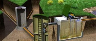
A modern version of an autonomous sewer system that can be calculated is a septic tank. It is classified as a local wastewater treatment plant (WTP). The principle of operation is the same as that of large wastewater treatment plants. With the help of several stages of purification, filtration, sedimentation, wastewater can be purified by 98%, and be quite suitable for various technical needs.
The design characteristics of an autonomous drainage system are also affected by:
- Pipeline depth;
- Number of plumbing fixtures;
- The type and characteristics of the soil in which the outer part of the autonomous sewage system will be laid.
The design parameters of the standard hydraulic calculation of an autonomous sewage system for a private house are regulated by SNiP 2.04.03-85. “Sewerage. External networks and structures.” This set of rules introduces concepts such as:
- Sanitary protection zone - depends on the type of sewerage structure, the volume of its productivity, calculated in meters;
- Average wastewater consumption - depends on the coefficient of unevenness of wastewater inflow into the sewer system and its consumption for production needs;
- Specific average daily water disposal per inhabitant of a settlement is an average volume indicator, but is taken as the basis in most calculations of sewerage systems. For the city - 500-550 l/s, for rural settlements - 125-150 l/s.
If melt and rainwater discharged into the storm drain are closed in a septic tank, then they are also taken into account as an additional volume of wastewater for the main sewerage system.
The same SNiP provides a hydraulic calculation of gravity sewerage, using the parameters of the cross-section of pipelines, the roughness of their walls and the speed of movement of wastewater through them. Additional requirements and a description of the principles of operation of various sewer systems, including autonomous ones, are contained in SNiP 2.04.02-84 “Water supply. External networks and structures.”
Important! The design parameters of the septic tank are also taken based on its periodic cleaning. It must be done in accordance with the instructions for using the equipment, but at least once a year.
Determination of effective storm sewer parameters
If a storm drain is installed in parallel with the fecal-domestic system, for correct calculations the following data must be taken into account:
- norm of annual precipitation in the region;
- area of the serviced facility;
- type of coating (concrete, soil, tiles);
- soil properties on the site;
- mass of rainwater drained.
All data, except the last point, is taken from the local geodetic service. Using the information obtained, gutters are selected according to their throughput. For example, let's calculate data on storm drainage trays using the formula: Q=q20∙P∙φ
Values:
- Q is the average annual volume of storm water in the region;
- q20 — coefficient for the region;
- P is the area of the object from which water will be drained;
- φ is the water absorption coefficient for different types of materials.
Having determined the throughput of the tray using this formula, gutters are selected in accordance with their technical characteristics. As a rule, this parameter is indicated on the product.
Calculation of internal sewage drains
As a rule, it is performed for two elements (the rest are accepted constructively). To begin with, the diameters are determined:
- the busiest riser,
- release.
To accomplish this task, there are tables and empirical formulas, nomograms that are given in the regulatory literature.
For the riser, it is calculated how much water it needs to flow per second. The calculation formula is simple:
qs = qtot + q0s,1
The terms here mean:
- qtot – estimated flow rate (l/s) of water on the site;
- q0s,1 is the maximum (per second) flow rate of the plumbing fixture with the greatest water removal (in residential buildings this is a volley discharge from the toilet, for which q0s,1 is taken to be 1.6 l/s).
For a horizontal pipeline, the calculation formula for sewage is more complicated:
qsg.tr = Qv /3.6 + Ks * q0
Where:
- Qв is the flow rate of discharged water for a given area, calculated using the formula, m3/hour;
- q0 is the flow rate from the device with the largest capacity (for residential buildings this is the drain of a bathtub holding 150-170 l, q0 = 1.1 l/s), l/s;
- Ks is the averaging coefficient.
However, as experts have found out, pipes with a diameter of 50 mm are sufficient for the trouble-free drainage of bathtub, sink, washbasin and other wastewater. To conduct toilet drains, a pipe diameter of one hundred millimeters is sufficient (this diameter is sufficient for risers and their ventilation).
Calculation of external sewerage
To design the outer part of the collector, calculate the following data:
- The length of communication from the outlet from the house to the connection to the septic tank or central highway.
- Pipe diameter (for private construction, tubes with a cross-section of 110, 160 or 220 mm are used).
- Waste volume. The norm is 2 cubic meters per person per month.
- The presence of turns and drop wells along the length of the communication.
To install a free-flow system, a slope must be observed. If, due to the peculiarities of the terrain, a pressure section of the sewerage system is installed, a special caisson is installed for the sewage pump and a siphon is installed. It will protect a section of the system from exposure to sub-zero temperatures and stagnation of fecal matter.
Calculation of the cesspool
To determine the required volume of a cesspool, it is necessary to multiply the average daily water consumption per person - 200 l/day. by the number of people living in the house, we multiply the resulting water consumption by all family members by 3 (for bacteria to fully process wastewater, it takes at least 3 days, preferably 5 days). Thus, for a family of three people, a cesspool will be required, the useful volume of which will be: 200 x 3 x 3 = 1800 liters or 1.8 m3. Accordingly, for a family of 4 people, 2.4 m3 will be required, for a family of 5 people – 3 m3, etc. The useful volume of a cesspool refers to the volume from the bottom to the level of the sewer pipe.
So, as mentioned above, a cesspool can be built from brick, monolithic reinforced concrete or reinforced concrete rings. Determining the required dimensions of a cesspool made of brick or monolithic reinforced concrete is not difficult, because cesspools made from these materials are usually made in a rectangular shape and are calculated by multiplying the length, width and height.
Calculation of cesspool volume
But to determine the volume of reinforced concrete rings you will need the following formula:
V=πD2H/4
where, V – design volume of the ring, m3;
π – 3.14;
D – inner diameter of the ring, m;
H – ring height, m.
Let us present the calculation results in a table.
| Product type | Product brand | Overall dimensions, m | Internal volume, m3 | Weight, kg | ||
| Wall thickness, m | Inner diameter, m | Height, m | ||||
| Reinforced concrete well rings | KS-7-9 | 0,08 | 0,7 | 0,9 | 0,346 | 410 |
| KS-7-10 | 0,08 | 0,7 | 1,0 | 0,384 | 457 | |
| KS-10-9 | 0,08 | 1,0 | 0,9 | 0,706 | 610 | |
| KS-10-10h | 0,08 | 1,0 | 1,0 | 0,785 | 660 | |
| KS-12-10 | 0,08 | 1,2 | 1,0 | 1,130 | 1050 | |
| KS-15-9 | 0,09 | 1,5 | 0,9 | 1,590 | 1000 | |
| KS-15-10h | 0,1 | 1,5 | 1,0 | 1,767 | 1240 | |
| KS-20-9 | 0,1 | 2,0 | 0,9 | 2,827 | 1500 | |
From the calculations it follows that for a family of 3 people, two pieces of reinforced concrete rings KS-12-10 should be used for the cesspool, the useful volume will be 2.26 m3, which is slightly more than the required 1.8 m3 (we always take with stock).
Accordingly for:
- For 4 people we use two KS-15-9 rings (useful volume will be 3.18 m3);
- For 5 people we use two KS-15-10h rings (the useful volume will be 3.534 m3).
Of course, you can combine reinforced concrete rings in any way you like, the main thing is that the wall thickness is the same, otherwise problems may arise with sealing the joints.
Sewer well made of reinforced concrete rings of different diameters
With a significant depth of the cesspool, in order to save money, they use this method: I place one or two rings of large diameter on the bottom, which will make up the useful volume, then a lid with a hatch is placed on them, and on top of the lid, offset in the center of the hatch, rings of smaller diameter are placed, which will rise 30-40 cm above the ground to prevent rainwater from entering the cesspool.
Pipe diameter and filling
Using special diagrams you can find out what the diameter of the pipes will be. It all depends on the speed of the wastewater, the slope of the pipes and the calculated wastewater flow rate. For example, the filling of a pipe is found through the ratio of the drain level (H) to the internal section of the pipe (d). In this case, the peak values of waste flow are achieved at a filling equal to 0.95, and it is inappropriate to rely on a filling greater than this value:
- when calculating the estimated flow rate, fluctuations in values at the time when the flow rate is maximum are omitted;
- drains most often move unevenly - thus, individual areas may be filled with more than the calculated values.
This means that in a household drainage system, a filling level of up to 0.8 is accepted. All recommended values are given in special SNiP tables. In domestic or industrial sewerage systems, the “reserve” of the pipe flow area is always taken into account, since there must be a space free of water inside. It provides air movement (purging) and removal of gases released from the water.
The calculation of gravity sewerage in general is very complex, since it is necessary to take into account the characteristics of each section of the pipeline, with different design conditions. In addition to formulas, other techniques are used: special diagrams, graphs, tables. High-quality work of designers is one of the main conditions for convenient operation of the system and its long-term trouble-free operation.
You can calculate the cost of a sewerage project using the calculator below: