GOST 19249-73* Soldered connections. Basic types and parameters
STATE STANDARD OF THE USSR UNION
SOLDER CONNECTIONS
MAIN TYPES
AND PARAMETERS
GOST 19249-73
USSR STATE COMMITTEE FOR PRODUCT QUALITY MANAGEMENT AND STANDARDS
Moscow
STATE STANDARD OF THE USSR UNION
| SOLDER CONNECTIONS Basic types and parameters Brazed and soldered joints. Main types and parameters | GOST 19249-73 |
By Decree of the State Committee of Standards of the Council of Ministers of the USSR dated December 4, 1973 No. 2641, the introduction date was established
from
01.01.75
Tested in
1989. Decree of the USSR State Standard dated 06.26.89 No. 2032 removed the validity period limit
1. This standard establishes the main types of soldered joints, the structural elements of your soldered joints, their designations and parameters.
2. The main types of solder joints and their symbols are given in table. .
3. The parameters of the structural elements of soldered seams and their symbols are given in table. .
Table 1
| Solder connection type | Typical cross-section of a solder joint | Connection symbol |
| Lap | PN-1 | |
| PN-2 | ||
| PN-3 | ||
| Telescopic | PN-4 | |
| PN-5 | ||
| PN-6 | ||
| Butt | PV-1 | |
| PV-2 | ||
| Kosostykova | PV-3 | |
| PV-4 | ||
| Tavrovy | PT-1 | |
| PT-2 | ||
| PT-3 | ||
| PT-4 | ||
| Angular | PU-1 | |
| PU-2 | ||
| PU-3 | ||
| touching | PS-1 | |
| PS-2 | ||
| PS-3 | ||
| PS-4 | ||
| PS-5 |
(Amended edition, Rev. No. 1
).
table 2
| Connection type | Structural elements of soldered seams | Name of structural elements | Letter designation of structural elements |
| Lap telescopic | Base material thickness | S | |
| Seam thickness | a | ||
| Seam width | b | ||
| Butt | Base material thickness | S | |
| Seam thickness | a | ||
| Seam width | b | ||
| Kosostykova | Base material thickness | S | |
| Seam thickness | a | ||
| Seam width | b | ||
| Bevel angle | α | ||
| Tavrova | Base material thickness | S | |
| Seam thickness | a | ||
| Seam width | b | ||
| Angular | Base material thickness | S | |
| Seam thickness | a | ||
| Seam width | b | ||
| Part connection angle | β | ||
| Bevel angle | α | ||
| touching | Base material thickness | S | |
| Radius of curvature of the soldered part | R | ||
| Seam width | b |
Notes:
1 - 5. (Excluded, From item No. 1).
6. Seam thickness a
determined by the size of the assembly gap and the physical and chemical properties of the soldered material and solder. The assembly gap values for the most common combinations of soldered material and solder are given in the reference appendix.
7. The amount of overlap is determined by the mechanical properties of the soldered material, the soldered seam and the requirements for the structure.
8. Thickness of soldered material S
installed when designing a soldered structure.
(Changed edition, Amendment No.
1).
4. Conventional images and designations of soldered seams in the drawing - according to GOST 2.313-68.
At the stage of preliminary and technical projects, a symbol for the type of solder joint is placed above the shelf of the leader line.
5. The rational shape of the fillet is a concave meniscus.
6. The shape and structural elements of the seams of solder joints, which are a combination of the main types, must be drawn with dimensions. It is allowed not to draw the shape and structural elements of the seams of combined solder joints on electrical installation drawings.
7. Combination solder joints widely used in industries are given in the reference appendix.
8. (Excluded , Amendment No. 1).
9. Symbols for seams of solder joints used in correspondence and documentation, except for working drawings, must consist of:
a) alphanumeric designation of the type of solder connection according to table. ;
b) cross-sectional dimensions and seam length.
An example of a symbol for a soldered weld of the lap type PN-1, 0.05 mm thick, 10 mm wide and 150 mm long:
Mon
—
1 0
,
05×10×150 GOST 19249-73
Note. The alphanumeric designations for seams of combined solder joints consist of alphanumeric designations of the main types, for example:
PN- 2
0
,
01×12×100 PV
-
1 0
,
02×5×100 GOST 19249-73
(Changed edition, Amendment No.
1).
ANNEX 1
Information
VALUES OF ASSEMBLY CLEARANCES FOR THE MOST COMMON COMBINATIONS “SOLDER MATERIAL - SOLDER”
| Solder name | Name of soldered material | ||||
| Copper | Copper alloys | Carbon and low alloy steel | Stainless steel | Aluminum and aluminum alloys | |
| Tin-lead | 0,07 — 0,20 | 0,07 — 0,20 | 0,05 — 0,50 | 0,20 — 0,75 | 0,05 — 0,15 |
| Copper | — | 0,04 — 0,20 | 0,001 — 0,05 | 0,01 — 0,10 | — |
| Copper-zinc | 0,04 — 0,20 | 0,04 — 0,20 | 0,05 — 0,25 | 0,02 — 0,12 | — |
| Copper-phosphorus | 0,04 — 0,20 | 0,04 — 0,20 | — | — | — |
| Silver-copper-phosphorus | 0,02 — 0,15 | 0,02 — 0,15 | — | — | — |
| Silver | 0,04 — 0,25 | 0,04 — 0,25 | 0,02 — 0,15 | 0,05 — 0,10 | — |
| Aluminum | — | — | — | — | 0,12 — 0,25 |
| Zinc | — | — | — | — | 0,10 — 0,25 |
APPENDIX 2
Information
EXAMPLES OF COMBINED SOLDER JOINTS AND THEIR SYMBOLS
| Typical cross-section of a solder joint | Connection symbol |
| PN-2; PV-1 | |
| PN-5; PV-2 | |
| 2PN-3; 3PV-1 | |
| 2PV-3 | |
| PV-2; PV-4 | |
| PV-1; 2PN-1 | |
| PV-2; 2PN-4 | |
| PT-1; 2PV-1 | |
| n PV-4, where | |
| PN-1; 4PN-2 | |
| PT-2; PV-1 | |
| 3PN-2; 2PV-1 | |
| 2PN-2; 2PV-1 | |
| 6PN-2; 4PV-1; PS-1 |
(Changed edition, Amendment No. 1).
CONTENT
| Appendix 1 Assembly clearance values for the most common “solderable material – solder” combinations. 4 Appendix 2 Examples of combined solder joints and their symbols. 5 |
CONVENTIONAL IMAGE AND DESIGNATION OF SOLDERING AND GLUING CONNECTIONS
GOST 2313-68 and ST SEV 138-74 establishes the rules for symbolizing and depicting seams of permanent joints obtained by soldering, gluing and riveting.
There is a distinction between hard and soft soldering. Solids include:
1. Copper-zinc: PM 36; PMC 48; PMC 54 according to GOST 1534-42;
2. Silver: PSr 10; PSr 12; PSr 25; PSR 45 and others according to GOST 8190-56.
Soft ones include:
1. Tin-lead: POS 90; POS 61; POS 40 according to GOST 1490-70;
2. Tin-cadmium.
Brazing is used to connect elements of tubular frames of bicycles, motorcycles, automobile radiators, refrigerator assemblies, turbine blades, etc. Soldering with soft solders is used in electrical and radio instrument making.
Seams of permanent connections obtained by soldering or gluing are shown conventionally according to GOST 2313-68.
Solder or glue in sections and views is represented by a line 2 times thicker than the solid main line.
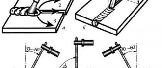
To indicate soldering, a sign in the form of an arc is used, which is applied on the inclined section of the leader line with a solid main line (Figure 19 a).
To indicate gluing, a sign in the form of the letter “F” is used (Figure 19 b).
Seams made by soldering or gluing along a closed contour (perimeter) are indicated by a leader line ending in a circle with a diameter of 3-4 mm (Figure 19 a).
Figure 19
When indicating invisible connection planes, instead of an arrow, use a dot that is placed inside the view outline.
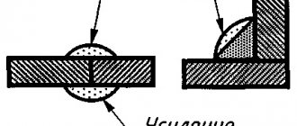
In the produced drawings, when depicting a solder joint, indicate, if necessary, the size of the seam and the designation of surface roughness (Figure 20).
Figure 20
The brand of solder or glue is indicated in the specification in the “Materials” section or on the part drawing in the technical requirements, indicating the number of the technical requirements item on the leader line shelf (Fig. 19 b).
Seams made along a closed line should be marked with a circle with a diameter of 3 to 5 mm, made with a thin line.
If necessary, the image of the soldered joint should indicate the dimensions of the seam and the designation of the surface roughness.
The designation of solder or glue (adhesive substance) according to the relevant standard or technical specifications should be carried out in the technical requirements of the drawing with an entry like: “POS 40 GOST...” or “Glue BF - 2 GOST...”.
If necessary, requirements for the quality of the seam should be given in the same paragraph of the technical requirements. A link to the item number should be placed on the shelf of the leader line drawn from the image of the seam.
When making seams with solders or adhesives of different brands, all seams made with the same material should be assigned one serial number, which should be marked on the leader line. In this case, in the technical requirements, the material should be indicated with an entry like: “POS 4 GOST...(No. 1), PMC 36 GOST...(No. 2), glue BF-2 GOST...(No. 3).”
RIVET CONNECTIONS
Table 1. Examples of conventional images of connections made by riveting.
| Type of connection | Image | Conditional image |
| in cross section | in sight | |
| 1. Rivet with a semicircular, flat, rounded head and with a semicircular, flat, rounded closing head | ||
| 2. Rivet with countersunk head and semicircular, flat, rounded closing head | ||
| 3. Rivet with countersunk head and countersunk closing head | ||
| 4. Rivet with a semi-countersunk head and a countersunk closing head | ||
| 5. Special rivets |
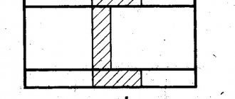
If the object shown on the assembly drawing has a number of similar connections with rivets of the same type and with the same dimensions, then the rivets included in the connection should be shown conditionally in one or two places of each connection, and in the rest - with center or axial lines (Figure 21 ).
Figure 21 – Image on the assembly drawing of a connection with the same rivets
If it is necessary to show several groups of rivets of different types and sizes in the drawing, then it is recommended to mark the same rivets with the same symbol (Figure 22a) or the same letters (Figure 22b).
Figure 22 - Examples of images on a drawing of a connection using various rivets
1) Welding
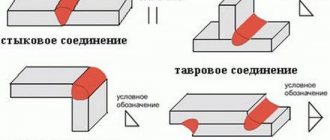
Currently, there are an extremely large number of types of welding and methods for their implementation GOST 19521-74 “Welding of metals. Classification" and to GOST 2601-84 "Welding of metals. Basic concepts. Terms and Definitions" . The symbols for the seams of welded joints and welding methods are just as numerous, therefore, when studying this topic, the student should only become familiar with the basic concepts of this type of permanent connection, the basic rules for depicting welded joints and some of their symbols. There are connections: butt (Fig. 38, a), lap (Fig. 38, b), corner (Fig. 38, c), T-joint (Fig. 38, d) and end (Fig. 38, e), indicated by symbols S, N, U, T respectively.
The edges of the parts to be welded can be prepared in various ways: without bevels (Fig. 38, b, c, d), with a bevel of one edge (Fig. 39.6), with a bevel of two edges (Fig. 38, a), with two symmetrical bevels of one edge (Fig. 39, b), with flanged edges (Fig. 39, a), etc. To distinguish them, a digital designation of the type of prepared edges is added to the corresponding letter symbol: C 1, C 2, C3 , etc. .; U1, U2, U3,…; HI , H 2, H3,…; T 1, T 2, T3…
The seam can be one-sided (see Fig. 38, d) and double-sided (see Fig. 39, b, c), continuous or intermittent with a chain (Fig. 40, a) or checkerboard (Fig. 40, b) arrangement of welded parts plots, point , etc.
It may be necessary to remove the seam reinforcement from both or one side (Fig. 41) or to process the beads and unevenness of the seam with a smooth transition to the base material.
The seam can be made when installing the product along a closed or open line , on a flux pad, on a steel or flux-copper pad, in a protective gas environment, with a consumable or non-consumable electrode, etc.
All this is reflected in the symbols of seams of welded joints in the relevant standards. For example, the rules for designating seams of welded joints made by manual arc welding are set out in GOST 5264-80 ; performed by submerged arc welding - in GOST 8713-79 ; performed by arc welding in shielding gas - in GOST 14771-76 . The main types, structural elements and dimensions of spot welded joints are given in GOST 14776-79 , etc. Therefore, in order to correctly mark the seam of a welded joint, you need to know the type of welding (arc or gas, manual or automatic, etc.), type seam (S, N, U, T) , the form of edge preparation, whether it is necessary to remove the convexities, whether welding will be performed during installation (which usually occurs when constructing steel frames of buildings and other structures), along a closed line or not, etc. .
In Fig. Figure 42 shows the structure of the symbol for a standard seam or a single weld point. All seams, regardless of the welding method, are depicted the same way. According to GOST 2.312-72 , a visible seam is depicted with a solid main line, and an invisible seam with a dashed line. A visible single weld point is marked with a “+” , made with solid main lines. Invisible single points are not depicted.
Rice. 42
The symbol of a seam is applied either on the shelf of a leader line drawn from the image of a seam or a single weld point on the front side, or under the shelf of a leader line drawn from the image of a seam on the back side, and a one-sided arrow is first made on the leader line. The front side of a one-sided seam is taken to be the side from which welding is performed; the front side of a double-sided seam with asymmetrically prepared edges is taken to be the side from which the main seam is welded. With symmetrically prepared edges, any side can be taken as the front side.
If all the welds shown in the product drawing, although of different types, are made according to the same standard, for example according to GOST 5264-80 , its designation is not indicated on the shelf, and this standard is referred to in the technical requirements located above the main one inscription.
Fig.43 — Fragment of a drawing with welding according to instructions
Explanation of the symbol of the seam - Welded lap seam (H2 - double-sided without beveled edges) using manual arc welding GOST 5264-80, leg size 6 mm, process sagging and unevenness of the seam with a smooth transition to the base metal. The seam on the left is knit, on the right is purl.