History of origin
Direct analogues of modern lathes were invented in ancient times. The drive was initially manual, and then foot driven.
Wooden products were usually processed on such a machine. To begin metal processing, we had to improve the design.
First, they came up with a machine in which they replaced the need to manually hold the workpiece with a mechanical holder.
The most widely used lathes were manufactured at arms factories. There they were improved, a caliper, a lead screw, and a gear set were invented. The actual activation of the caliper has already been made automatic on some equipment models.
This is how equipment was produced until the beginning of the 20th century, and after the revolution a gearbox appeared. Allowing you to change the processing speed of the workpiece.
Device
The headstock is attached to the bed, as well as all the main parts of the machine and the tailstock. The main elements in all machines have an identical structure and a general operating principle.
Design elements:
- the fundamental framework where the controls and everything else are placed;
- quill – fastening component;
- one-piece metal body; a control lever that allows you to directly secure the quill and the base of the entire tailstock;
- a flywheel responsible for moving the quill;
- a screw with which the element is clearly secured in relation to the rest of the lathe and all its parts.
Since all the components are identical, the operating principle is not too different.
Principle of operation
The central part of the tailstock is attached to the caliper. Through it, the headstock receives translational motion, since it is equipped with an independent gear drive.
Some types of equipment produce rotational motion. The center of the tailstock itself does not rotate. The specific drive method depends on the modification of the machine, as well as on the tasks that need to be solved.
Node purpose
The main function is to securely secure the workpiece. The unit also supports the second edge of the workpiece and controls stable rotation.
When carrying out the drilling process, the tailstock is connected to the caliper, and a drill of the required size is inserted into the quill chuck.
Gearbox
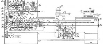
A gearbox is a set of gears with two kinematic chains for accelerated and decelerated transmission of rotation to the spindle.
The gears are switched using handles located on the front panel of the headstock. In this case, the different combination of gears engaged determines the number of spindle revolutions per unit time. The ratio of rotation speeds is subject to a geometric progression, that is, each subsequent speed is equal to the previous one, multiplied by the same number.
Gearboxes can be separate or combined with a headstock. The main part of the separate box is located in the left cabinet, the speed selection device is located in the headstock. This is necessary to protect the spindle from vibration and heat from the gearbox.
Most lathes have a combined gearbox located in one place - the headstock. This achieves a compact design of the spindle drive and concentration of control on one front panel.
The spindle speed is adjusted by engaging the gear elements of the box in various combinations. For these purposes, modern machines are equipped with a single-handle mechanism, which moves several moving elements of the box in one movement.
A preselective or preliminary spindle speed switching mechanism is more productive. The external panel has a rotary disk with a speed indicator. The turner aligns the disk pointer with the number of revolutions on the panel, and then uses the power handle to set the machine to rotate at a given speed.
In addition to gears, modern machines can use a stepless method to drive a spindle. The use of a variable speed drive motor allows torque to be directly applied to the spindle. In this case, the spindle can rotate at any speed in the range limited by the characteristics of the machine, the design of the headstock becomes more compact.* (min. speed increment is 1 rpm)
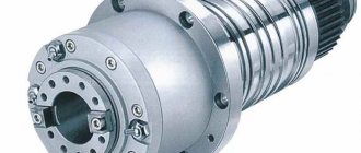
Spindle
A spindle is a rotating shaft, at the front end of which a chuck is attached for clamping workpieces. The spindle rotates in high-precision rolling bearings. To eliminate gaps, the front support is equipped with an adjustable bearing with a tapered inner ring.
The bearing is adjusted using a special nut. When the nut is tightened, the inner ring moves along the spindle, eliminating gaps formed during operation. The rear spindle support rotates in two thrust bearings that have a similar adjustment.
Requirements for the spindle unit
The spindle assembly is the main element of the lathe. The quality of parts processing and productivity depend on its condition. Let's consider the requirements for the spindle:
- Rotation accuracy. Specified by the relevant standards. This parameter depends on the type and purpose of the machine, accuracy class. Special machines have their own technical conditions.
- Spindle rigidity. Should also be determined by relevant standards. Typically, the permissible spindle deflection is determined by its radial runout. The amount of deflection should be less than one third of the amount of runout.
- Vibration resistance. This characteristic affects the quality of finished products.
- Spindle speed. The higher the rotation speed, the higher the quality of the processed surface. Speed depends on the design features and purpose of the machine.
- Load bearing capacity. Depends on the choice of spindle supports and the correct supply of lubricating fluids.
- Durability. This parameter directly depends on the quality of the bearings in which the spindle rotates.
- Permissible heating of bearings. Determined by the accuracy class of the machine.
Spindle assembly designs
The designs of spindle units differ in many respects: in the performance of specific work and the accuracy of their execution, dimensions and, as a consequence, transmitted power, method of transmitting torque and rotation speed.
In modern high-speed machines, spindle rotation is no longer possible with traditional bearings. Air, magnetic supports of the rotating spindle are used here. In this case, the deviation from, for example, roundness may not exceed 0.2 microns. Whereas a spindle on bearings gives a deviation of up to 1 micron.
There are precision spindles with a machining error of only 0.025 microns. Such a spindle is driven into rotation by an inertial drive. The spindle with the flywheel accelerates to a given speed, then it is disconnected from the drive and continues to rotate by inertia.
Machine setup
Setting up a lathe means preparing its kinematic diagram to perform tasks defined by the technological map.
Before setting up, all controls are set to the neutral position.
The kinematic chains of the main movement are adjusted first: the controls are installed in a position corresponding to the required spindle rotation speed. This value will determine the cutting speed.
The set spindle rotation speed is determined by the rationality of certain processing modes for specific products. In addition to the spindle rotation speed, the feed rates and feed rates of the cutting tool play an important role in machining.
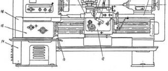
Headstock device
The main component of the front tank is the spindle. The spindle head is fixed to the left edge of the bed. This is the most important detail of the entire structure.
Various necessary fixtures, tools, and mandrels are fixed in the inner conical hole of the spindle.
How does it work
The movement of the spindle is transmitted from the V-belt pulley. All shafts and the spindle itself are mounted on rolling bearings.
When the machine rotates in a forward direction, large torques are required. This occurs due to the large number of discs that are located on the left side of the friction clutch.
If the gearbox is fixed in the bed frame, then it is connected to the spindle by a belt drive. Such equipment models are called split-drive machines.
What is it for?
The headstock carries out the main movement and transmits torque from the drive motor directly to the workpiece.
If the machine is universal, then the headstock, with the help of structural elements, drives the feed of the support with the cutting tool.
Restoration with acrylic plastic
- The hole for the spindle is expanded with the help of removing metal 3-4 millimeters thick. Ovality indicators should not exceed half a centimeter.
- A hollow frame is mounted in the headstock spindle. The outer diameter of the cylindrical mandrel is equal to the outer diameter of the updated quill.
- Relative to the quill axis, the mandrel is installed from the center. Before this, you should attach a special gasket (for example, made of paper) into the conical hole of the quill.
- After this, the runout corrections are tested and adjusted. The indicators should be in the region of 0.16-0.19 mm. Then the quill is mounted so that the forming mandrel is located above it with a slight deviation. This position of the part guarantees the difference in the height of the centers and the headstock at the required level (0.06-0.08 mm).
- Three small holes (about 7 mm in diameter) must be drilled above the spindle hole. They should be located in the middle and on the edges of the tailstock housing.
- The gap in the body is treated with a degreasing agent and dried for 25-30 minutes.
- The mandrel is treated with soap and the tailstock housing is mounted. The part must be secured to the frame using bolts.
- The hole for the quill should be sealed using special rings and plasticine. The same must be done with the holes for attaching the spindle.
- Three plasticine funnels are made above the previously made three holes.
- The previously prepared acrylic solution is poured into the middle funnel. It must be poured until the outermost funnels are partially filled.
- Then the tailstock treated with acrylic plastic is left to dry at a temperature of 19-20 degrees.
- After this, the assembly is shifted and cleaned of plasticine residues, special grooves are created, holes are made, a key-type groove is formed, and the entire tailstock structure is finally assembled.
The tailstock is one of the key components of a lathe. That is why every operator of such an installation must know the structure of this part and have minimal information about the most likely causes and “symptoms” of its failure. It is worth noting that even though the simplest unit breakdowns can be fixed on your own, it is always better to consult a specialist.
Source
Adjustment and repair
The adjustment includes the required steps:
- setting the amount of play that forms between the guides at the bed and the base of the tailstock;
- minimum clearances in the quill bearings if it rotates;
- eliminating the center offset relative to the spindle.
How often it is necessary to check and its procedure are indicated in the passport documentation for each machine.
If the need arises, restoration or repair work is carried out. The following parameters are restored:
- precise joining of the frame with the tailstock assembly;
- height of the spindle and quill.
It is also often necessary to restore the accuracy of the hole where the quill is attached.
Tailstock functions
This element of the machine’s design is responsible for the quality of fixation and processing of parts. That is why sustainability should be a very important characteristic of it. This unit prevents the part from shifting during processing and should be responsible for the correct location of the center axis. In addition, this part is responsible for the correct direction of the spindle and its stable fixation.
In addition to these functions, such a unit must also have the ability to quickly install on the machine axis and the option of accurately fixing the part on both center holes of the machine. It is the stability and stability of the tailstock that contributes to the precise processing of workpieces.
DIY front and rear quill
The spindle head is a priori the most complex element of all equipment. During manufacturing, it is necessary to take into account that you will need a block of replaceable gears that transmit and change the speed of the rotational movement of the spindle and the torque directly from the gearbox shaft.
The tailstock is made with a movable or fixed center of rotation. For a movable version of the center, you will need to install a pair of bearings in the quill hole: the front edge with a conical roller, it will be thrust and the rear, radial, bored to a cone.
Installation and fixation of the rear center on the machine is carried out due to the conical hole of the sleeve. The spindle and thrust head are the basis of the design of any lathe.
Therefore, the master must know the principle of their operation, how to make such a part with his own hands and how to adjust it, and, if possible, repair it.
Table of contents
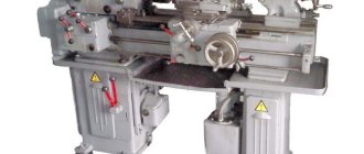
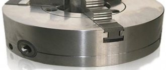
The tailstock of a lathe is designed to support the workpiece being processed, which is attached directly to this unit. Here the workpiece rotates about its axis while it is being processed by a cutting tool. You can also attach the tools themselves to the devices, such as countersinks, drills, taps, dies, centers, reamers, and so on. It is located on the frame, and the position of the center in this case depends on the exact sequence in which the bolts are fastened. During the adjustment process, you should avoid blows to the body, as they can disturb the center position. Therefore, problems may arise regarding how to position the tailstock. This technical unit of the machine is moved manually, as it moves along the guides of the frame. Fastening operations are carried out using a handle.
Read also: Mixer for drill for mortar
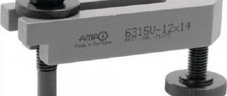
photo: tailstock of lathe
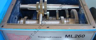
The 1K62 screw-cutting lathe itself, as well as other models, is used for processing parts such as shafts, disks, bushings and other cylindrical workpieces. They are processed by turning, which takes place inside and outside the part, depending on the cutter used. This equipment is very common in modern industry, so all its components are precisely calibrated.
Tailstock device of a lathe
This element of the lathe has the following main structural details:
- Device base or plate;
- Tailstock housing
- Pinol;
- Flywheel (quill movement wheel);
- Flywheel handle (tailstock fixation);
- Screw for transverse movement of the tailstock.
photo: tailstock device of a lathe
As a rule, the slab in all models is made flat. During operation, ensure maximum secure fastening. The protrusion of the cross member must be located in the slot formed by the machine guides.
Working principle of the tailstock
The tailstock of a lathe has a hole in the quill where machining tools are inserted. During operation, it moves along the bed to select the appropriate distance corresponding to the size of the workpiece being processed. Depending on the type of work, both rotating and stationary parts are placed in the tailstock. All movements are carried out during the preparatory processes, while during operation this unit remains motionless.
Basic movements
The tailstock of the lathe moves when the protrusion of the bars engages. At the same time, automatic movement of the caliper may be activated.
The tailstock is moved along the bed using a special handle. This can be used to position the workpiece in the center of the device, to bring the cutter to the part, and also to rotate the turret. If the machine is of medium size, then the movement occurs due to the rotation of a small gear, which is located in the bracket. It engages with the lathe of the machine. If the size of the machine is large, then this procedure is carried out using an electric drive.
The quill moves in the axial direction. The feed movement here also occurs using axial movement. There is no difference here whether the cutting tool or the workpiece being processed is fixed in the quill, since the rotational movements are determined by the operations performed on the machine.
Tailstock alignment and adjustment
Before inserting the part into the tailstock, it should be adjusted. First of all, you need to determine the alignment. To do this, the tailstock of the 1K62 lathe is brought to the top of the opposite unit so that the distance between them is no more than 0.5 mm. After this, you need to secure the quill and check, perhaps by eye, how much the vertices coincide on the horizontal plane. If they do not match, then the alignment is adjusted by moving the rear tank.
Another adjustment method involves clamping the workpiece in the cams and then grinding it along the diameter, which should coincide with the diameter of the tailstock quill. Measurements here are made with a micrometer. On the quill itself and on the groove, the indicator is set to the zero position. To avoid play during adjustment, everything must be securely clamped. The part should also be pressed at the centers with the same force. This test grinding allows you to adjust the tailstock for serial work with a batch of parts and achieve accuracy up to several hundredths of millimeters of error.
Tailstock repair
Repairing a 16K20 tailstock often involves restoring the accuracy of the mating surface of the body, frame and bridge, as well as setting the correct centers and restoring the accuracy of the holes in the body. Restoring the holes that are intended for the quill is one of the most labor-intensive operations. They are repaired using lapping, as well as boring, which requires subsequent finishing with acrylic layers. For slightly worn holes, ordinary lapping is suitable, and the centers are restored using compensation pads.
When repairing tailstock quills, operations are used to grind the surface of the outer diameter. To restore the conical hole, use a compensation sleeve. This product has a cylindrical shape on the outside and a conical shape on the inside. It is often made from alloy steel and then hardened. The outer diameter of the bushing should be made according to the boring hole and at the same time have a small gap, approximately 0.05 mm.
The bearing holes on the housing often have to be repaired. Repair is carried out by replacing the housings of the worn-out unit. After this, you need to adjust the internal diameter to the existing bearings, and also check the radial runout.