Repair of welded seam of metal structures
Repair of welded joints
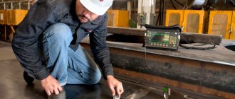
Repair of welded joints includes operations to identify defects, prepare defective areas for welding and the welding process itself. For methods of determining defects, see table. 9. Parts to be restored are subjected to certain preparation. Oily parts are “boiled” in a hot solution of caustic soda, then washed with warm water. The surfaces of the parts are also treated with organic solvents (kerosene, etc.), cleaned by sandblasting, sanded with a file, and then carefully inspected.
If there are cracks, the parts are prepared for welding as follows. After cleaning the surface, holes with a diameter of 3.3.5 mm are drilled at the ends of the crack so that the crack does not spread further (Fig. 48, a). Along the entire length, the cracks are cut manually or chamfered on a machine (Fig. 48, b). If the thickness of the part exceeds 12 mm, the chamfer is removed from both sides (Fig. 48, c). Sometimes, for greater strength of the weld, several pins are installed along the crack (Fig. 48, d). The crack is welded using arc or gas welding.
Small cracks in unimportant places are eliminated with short transverse welds, which, when cooled, tighten the crack. Cracks on parts made of aluminum alloys are cut until a groove with a depth and thickness of up to 3 mm is obtained (cracks on parts up to 10 mm thick are not cut).
When repairing parts by welding pads, the surface around the crack is cleaned. There should be 25.30 mm between the edges of the overlays and the crack (Fig. 48, d).
Rice. 48. Scheme for preparing parts for welding cracks:
a - drilling holes; b and c - formation of a chamfer; g - installation of studs; d — preparation for welding of linings; b—part thickness, mm
Source
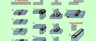
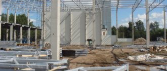
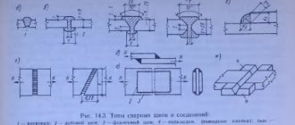
Types of welded joints of metal structures
The classification of welded joints is divided according to several criteria.
- The location of the junction of two workpieces.
- Weld type.
- Welding operation technology.
- Conditions under which the welding process is carried out.
- Workpiece thickness.
- Grade of steel blanks.
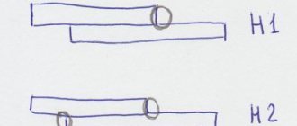
As for the first point, that is, the geometry of the arrangement of the workpieces, there are four types of butt joints.
- Butt joint, when two workpieces are adjacent to each other in the same plane.
- Overlapping, when two parts overlap each other with their edges.
- Gusset. This is when two metal pieces are connected at any angle.
- T-joint. This is when one of the parts is adjacent to another with its end plane.
Most often, butt and corner joints are used in metal structures. How to properly carry out these connections between two workpieces.
As for the butt joint, it is performed by direct full penetration of the weld over the entire thickness of the workpieces. Or they use technology for welding using lead strips. If welding is not carried out in a workshop, then the connection can be carried out with one-sided welding and with further welding of the root of the weld. That is, filling the gap between the edges is carried out along one of the edges, gradually filling the entire gap.
The technology with lead pads is very different from the previous one. Firstly, the linings are installed on the side of the edges of the parts being welded. Secondly, the gap between the edges should be within 7 mm - this is for manual welding. With mechanized - 16 mm. Thirdly, you will have to choose the thickness of the lining so that during welding a burn does not form on them. In this case, the welding process mode itself is taken into account with the required current value being set.
Often in metal structures, two workpieces of different thicknesses are joined in butt joints. In this case, using the milling or gouging method, the angle of inclination of the edge of thick metal is selected, which is equal to a slope of 1:8 for tensile elements of a metal structure (for example, suspension and console), and 1:5 for compressed elements (supports and racks).
Fillet welded joints are subject to greater loads than butt welded joints. It is especially necessary to note the tensile loads along the thickness of the workpiece. Therefore, there are certain requirements for this type of welded joint.
- One-sided corner joints cannot be used for loaded metal structures. The best option is a double-sided seam, which reduces the concentration of deformations in the very top part of the roller.
- If for some reason it is not possible to apply a double-sided seam, then use a one-sided one. In this case, edge cutting is not used, and the amount of deposited metal should be as small as possible. That is, in this case, complete weld penetration is not used.
- If the metal structure is subjected to static loads, then partial seam welding is used with cutting the edges of two workpieces.
- It is better to use a K-groove rather than a V-groove.
- If possible, it is better to avoid corner connections of metal parts. Preference should be given to the T-joint.
The welding mode is also an important factor that determines the quality of the weld. If we talk about current, then its increased value can create an uneven distribution of metal in the joint area. Burn-throughs may even form if the current is high and the thickness of the workpieces being welded is small. A small current is also the cause of poor weld quality. Areas with undercooking may form, which leads to a decrease in the strength of the joint and the formation of cracks inside the fused metal.
Welding speed can also affect quality. For example, if the speed is high, then this is a guarantee of poor welding of the joint. The gap may not be filled completely. If the speed is low, burns may form, the metal being filled in the gap forms bulges and spreading. Therefore, it is necessary to control the speed of manual welding. Its average value is 20 m/h.
Wood and metal processing
Repair of welded joints includes operations to identify joint defects, preparation of defective areas for welding and the welding process itself.
Methods for determining defects are varied and depend on the nature of the connection. The simplest way to check is an external inspection, which aims to identify welding defects that appear on the surface. These defects are pores, cracks, lack of penetration, burns, etc. When inspecting, use a magnifying glass. The tightness of the seam can be determined by a kerosene test. To do this, apply a thin layer of chalk diluted in water to the outside of the area being tested. After drying, apply a rag generously moistened with kerosene to the inner surface of the joint, and if after 10-15 minutes darkening (moisture) appears on the chalk layer, this indicates a leak in the weld or a crack. These defects are usually eliminated by welding.
Welded joints that carry heavy loads, the quality of which is subject to the highest requirements, for example in high-pressure boilers, etc., are subjected to X-ray scanning, magnetic and ultrasonic testing.
The parts to be restored are subjected to certain preparation. Oily parts are boiled in a hot solution of caustic soda, then washed with warm water. The surfaces of parts are also washed in organic solvents (kerosene, etc.), cleaned by sandblasting, filing and other methods. The parts are then carefully inspected. If they have cracks, they are prepared for welding as follows.
After cleaning the surface, holes with a diameter of 3-3.5 mm are drilled at the ends of the crack so that the crack does not spread further. The cracks are cut along the entire length manually or chamfered on a machine. If the thickness of the part exceeds mm, the chamfer is removed from both sides. Sometimes, to increase the strength of the weld, several studs are installed along the crack. The crack is welded using arc or gas welding.
Rice. 1. Scheme of preparation of parts for welding cracks: a - holes are drilled at the ends of the crack, b - chamfered, c - chamfers on both sides, d - installation of studs, O - welding of linings
Small cracks in unimportant areas are sealed with short transverse seams, which, when cooled, tighten the crack. Cracks on parts made of aluminum alloys are cut to obtain a groove with a depth and thickness of up to mm. Cracks on parts up to mm thick cannot be cut.
When repairing parts by installing overlays, the surface around the crack is cleaned so that its edges are 25 - 30 mm away from the crack.
Source
Innovative welding technologies
Over time, the classical method of performing welding work was improved, experienced specialists developed innovative ways to connect metal parts into a single structure: welding using laser systems, ultrasound, thermal effect, etc.
Such innovative ideas can help the welder in his work, making some tasks easier and speeding up the entire process of assembling metal structures as a whole. For this reason, scientific development and research continues in this area today.
Methods of welding metal structures.
Also, the use of innovative technologies for performing welding work allows the welder to receive a number of advantages:
- reduce metal warping rates;
- increase the speed of work;
- reduce the cost of cleaning the weld seam;
- reduce costs for purchasing consumables;
- make connections of thin sheet metal.
The following welding technologies are especially interesting from the point of view of productivity, quality of the resulting seams and cost-effectiveness:
- Electron beam welding is used when working with deep joints - up to 20 cm, but only under the condition of a certain ratio of the width of the seam and the immersion depth of the tool - 20:1. The seam formation process is carried out in a vacuum, so it is almost impossible to use this technology in everyday life. It is used in the field of narrow-profile industries.
- Thermite welding involves applying a special mixture to the joining contours of parts during the combustion process. The technology is used for critical structures made of finished metal, when it is necessary to eliminate an existing defect in the form of a crack or chip using metal surfacing.
- Plasma welding involves the use of ionized gas passing through electrodes with high welding characteristics and performing the function of an arc. The technology has wider application possibilities compared to the electronic type, as it allows the welder to cut and weld a metal structure with any width of metal.
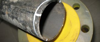
- Orbital argon arc welding using a tungsten electrode is used to work with complex metal parts. For example, for fixed joints of pipes with a diameter of 20-1440 mm. During operation, activating flux is applied to 1 g/m of the seam. This makes it possible to solve a number of important technological problems: reduce the volume and weight of the weld pool by conducting operations with reduced current; due to the pressure of the arc on the liquid metal, the seam is of high quality in any spatial position; welding can be automated without cutting edges.
- Gentle welding technologies in Ar+CO2 and Ar+O2+CO2 shielding gas mixtures. When using this method of welding, better connections can be obtained when compared with welding in CO2. At the same time, the actual volume of consumables will be reduced by 20% due to a sharp reduction in the spattering of electrode material, and the transition to the welded parts of the metal structure will become smooth.
On a note! Each of them has a number of disadvantages and is distinguished by its unique features and principles of implementation, which are important to master before starting to use it in practice.
Modern science is multifaceted and unpredictable.
It provides a person with the opportunity to put into practice the advantages of nanotechnology, so the near future of welding operations seems to be associated with the improvement of computer welding control circuits, as well as the use of new welding materials.
A COMMON PART
1.1. Purpose and scope
1.1.1. This guidance document (RD) is intended for personnel carrying out assembly and welding work during the enlargement and installation of metal structures of industrial buildings.
Compliance with the requirements of this RD for the organization and technology of assembly and welding of metal structures ensures the production of welded joints that meet the quality indicators established by the standards, with minimal labor costs. The RD is a guiding document for the development of work projects and other technological documentation.
1.1.2. RD applies to manual arc welding with stick electrodes, mechanized (semi-automatic) welding with self-shielding flux-cored wire and in carbon dioxide, automatic and mechanized submerged arc welding in construction and installation site conditions.
1.1.3. This RD defines the technology of assembly and welding work during the enlargement and installation of metal structures made of carbon and low-alloy steels in accordance with GOST 27772:
shaped steel (angles, I-beams, channels) - from steel C235, C245, C255, C275, C285, C345, C345K, C375;
sheet, universal rolled and bent profiles - from steel S235, S245, S255, S275, S285, S345, S345K, S375, S390, S390K, S440.
The designation of steels according to GOST 27772 (by yield strength) and the corresponding steel grades according to other current standards are given in Appendix 1.
The RD operates in conjunction with the following regulatory and technical documents (NTD):
SNiP 3.03.01—87. Load-bearing and enclosing structures;
SNiP II-23—81*. Design standards. Steel structures. M., 1991.
1.1.4. The guidance document contains the basic provisions for organizing welding work on construction sites, instructions on the selection of welding materials and equipment;
requirements for the assembly and welding of structural elements, welding modes, control procedures and standards for assessing the quality of welded joints.
In addition, this RD provides recommendations on welding technology for individual typical, most common components of steel structures.
1.2. Qualification requirements for welders, inspectors and engineers
1.2.1. Welding of metal structures of industrial buildings must be carried out by welders who have certificates for the right to carry out the relevant welding work, issued to them in accordance with the requirements of the “Rules for Certification of Welders” approved by the State Mining and Technical Supervision of Russia.
Welders who have a certificate for the right to weld these steels are allowed to weld structures made of steels with a yield strength of 390 MPa (40 kgf/mm 2 ) or more.
Welders-operators who have completed a special course of theoretical and practical training and passed tests for the right to perform these works are allowed to use mechanized welding methods.
Welders of all specialties and qualifications must pass tests for the 2nd qualification group for electrical safety. In addition, all welders must pass fire and safety tests.
1.2.2. A welder starting welding for the first time in this organization must weld test (permitted) samples before being allowed to work, regardless of whether he has a certificate for the right to perform the relevant work. Welding of test samples should be carried out under conditions identical to those in which welding of structures will be performed.
The design and number of test samples are established by the welding supervisor depending on the types of production connections and the qualifications of the welder. The quality of test welded joints is determined by visual inspection to determine the continuity and formation of the seam, and if necessary (at the discretion of the welding supervisor) - using non-destructive physical testing methods.
The quality of test welded joints must be assessed according to the standards provided for the same production joints. Test connections must be identical or of the same type in relation to those production connections that will be welded by the welder being tested. Characteristics of welded joints of the same type are given in the “Rules for Certification of Welders”.
1.2.3. Welders are allowed to perform the types of work specified in the certificate. The certificate must list the steel grades or groups of steel grades in accordance with the “Rules for the Certification of Welders” that the welder is allowed to weld.
1.2.4. For welding at temperatures below minus 30°C, the welder must first weld test butt samples at a temperature not higher than the specified one. If the results of mechanical tests of test samples are satisfactory, the welder may be allowed to weld at a temperature 10°C lower than the welding temperature of the test samples.
1.2.5. Welding work must be supervised by a person who has a document of special education or training in the field of welding.
Engineering workers who have studied this RD, the relevant SNiP, working drawings of products, production and technological documentation (PTD) for welding and methodological instructions for control are allowed to supervise welding work, control welded joints and operational control. The knowledge of engineers and their professional training in welding production must be checked by a commission appointed by order of the head of the enterprise. Engineers' knowledge is tested at least once every three years.
1.2.6. Inspectors who have completed a special program of theoretical and practical training and have received a certificate for the right to perform work on flaw detection of welded joints using the appropriate type (method) of inspection are allowed to perform work on quality control of welded joints. Inspectors for physical control methods must be certified in accordance with the “Rules for Certification of Non-Destructive Testing Specialists”, approved by the Gosgortekhnadzor of Russia on August 18, 1992.
1.2.7. The training of inspectors should be carried out by special educational institutions or professional training units (training centers, centers, courses, etc.) of enterprises that carry out welding quality control work and have a license to carry out such work.
The training of inspectors must be specialized in inspection methods (ultrasonic flaw detection, radiography, etc.), and, if necessary, in the types of welded joints, which must be indicated in their certificates. Each controller can only be allowed to use those control methods specified in his certificate. An inspector who has had a break in work (for this type of control) for more than 6 months must retake the exams in full.
1.3. Basic provisions for organizing welding work
1.3.1. When developing a work project (PPR) for the installation of metal structures of buildings, the conditions for assembling structures for welding, welding and control of welded joints must be taken into account and reflected.
The PPR should include the most advanced technology for assembly and welding work with an optimal level of mechanization.
1.3.2. When organizing and performing work on assembly, welding and quality control of welded joints, all conditions must be created for compliance with safety and fire safety rules in accordance with the requirements of the following regulatory documents:
SNiP III-4—80. Safety in construction;
GOST 12.3.003. System of occupational safety standards. Electric welding works. Safety requirements;
“Rules for electrical installations”;
“Rules for technical operation of consumer electrical installations”;
“Safety rules for the operation of consumer electrical installations”;
“Sanitary rules for X-ray flaw detection”, No. 2191-80;
“Sanitary rules for radioisotope flaw detection”, No. 1171-74;
“Sanitary rules for welding, surfacing and cutting of metals”, No. 1009-73;
“Fire safety rules when carrying out welding and other hot work at national economic facilities”;
“Fire safety rules during construction and installation work. PPB 05-86".
1.3.3. The organization performing assembly and welding work must ensure the proper quality of welded joints through:
using proper equipment;
use of welding materials of appropriate quality that have passed appropriate control;
fulfillment of technological requirements for assembly and welding of products regulated by PDD;
performing operational control of assembly and welding processes;
timely implementation of quality control of finished welded joints.
1.3.4. The use of basic materials (sheets, rolled profiles) and welding materials (electrodes, welding wire and fluxes) that differ from those specified in the production and technological documentation (PTD) may be allowed by a joint technical decision of the organization that developed the PDD, an industry specialized organization and an organization - producer of the work.
1.3.5. The order of assembly and enlargement of mounting blocks and the sequence of work should ensure the possibility of using the most advanced welding methods. To ensure proper quality of welded joints and increase labor productivity when performing work on assembly, welding and quality control of welded joints, one should be guided by the provisions set out in this section.
1.3.6. The method of welding metal structures at different stages of their enlargement and installation must be determined by the work execution plan (WPP).
When choosing a welding method, keep in mind:
the feasibility of using mechanized welding methods must be confirmed by technical and economic calculations;
automatic submerged arc welding should be used in the enlarged assembly of structures for seams of considerable length;
mechanized (semi-automatic) welding with self-shielding flux-cored wire can be used when enlarging and installing metal structures for welding seams in the lower, inclined and vertical positions;
mechanized (semi-automatic) welding in carbon dioxide (solid wire) should be used for enlargement and assembly welding of metal structures in any position of the seam, provided that the welding site is protected from the wind.
In cases where automatic and mechanized welding cannot be used, manual arc welding should be used.
1.3.7. The number of welding engineers and equipment adjusters for mechanized welding at the construction and installation site depends on the volume of welding work and the number of welders working. It is established in accordance with the regulations on the welding service of the construction and installation organization.
1.3.8. Supplying the enlargement site and the territory of the building being installed or reconstructed with power supply for welding purposes should be carried out using electric welding current distributions to all areas of the enlargement site and the building being assembled.
1.3.9. The cross-section of the wire for connecting the power source for welding to the network should be selected according to the data in table. 1.1. In manual arc welding, the electrode holder is connected to the welding circuit with a flexible copper wire with rubber insulation of the brands PRD, PRI, KOG 1, KOG 2, the cross-section of which must be selected depending on the welding current: at a current of up to 100A - at least 16 mm 2, at 250A - 25 mm 2, at 300A - 50 mm 2. The length of the flexible wire must be at least 5m.
Wire cross-section for connecting welding power sources to the network
| Maximum welding current | Cross-section of copper* wire, mm 2, at mains voltage V | |
| power supply, A | 220 | 380 |
| 300 | 16 | 10 |
| 500 | 35 | 16 |
| 1000 | 70 | 50 |
| 2000 | — | 120 |
| 4000 | — | 240 |
* The cross-section of the aluminum wire should be 1.5 times larger
1.3.10. If there is a large volume of assembly and welding work, the supply of assembly sites and the building under construction with oxygen and flammable gas for cutting should be carried out centrally using wiring from the power center to the cutting stations. The feasibility of using a centralized power supply system must be confirmed by calculation.
The distribution of oxygen and flammable gas throughout the building of a large industrial facility should be provided for in the design as a permanent gas supply system, remaining after completion of construction to carry out repair work during the operation of the facility.
Centralized gas distribution at the construction site is carried out as a temporary gas supply in accordance with the PPR.
1.3.11. Depending on local conditions, acetylene, propane-butane or natural flammable gas is used as the cutting fuel gas. Acetylene for cutting is used only when construction is located at a significant distance from oil refineries and natural gas pipelines, when it is technically impossible or economically infeasible to use propane-butane or natural gas.
1.3.12. Construction and installation sites are supplied with oxygen from their own stationary oxygen installations (such as KGN-30, 2KG-30, etc.), or from a gasification station, where liquid oxygen, delivered to the site in railway or road tanks, is gasified and sent through a gas pipeline to workplaces or into an oxygen ramp. The method of oxygen supply depends on local conditions and must be confirmed by calculation.
1.3.13. The supply of liquefied propane-butane must be carried out using special automobile tanks from the supplier plant. At construction and installation sites, underground tanks are constructed where propane-butane is stored; Gasified propane-butane is supplied from tanks to places of consumption.
1.3.14. The design, construction, testing and operation of oxygen and flammable gas pipelines must be carried out in accordance with the “Safety Rules in the Gas Industry” (Gosgortekhnadzor, 1992).
1.3.15. The surfaces of the structure to be welded and the welder’s workplace must be protected from rain, snow, wind and drafts.
At ambient temperatures below minus 10°C, it is necessary to have an inventory room for heating near the welder’s workplace, and at temperatures below minus 40°C, welding should be carried out in a heated greenhouse, where the temperature should be above 0°C.
1.3.16. At each construction and installation site, a warehouse must be equipped in a warm heated room for storing welding material (electrodes, wire and flux). The temperature in the warehouse must be maintained at least 15°C, and the relative humidity should not exceed 50%.
Welding materials must be stored separately by brand, batch and diameter under conditions that protect them from moisture and mechanical damage. Welding flux should be stored in an airtight container.
The warehouse must be equipped with ovens for calcining electrodes, flux-cored wire and flux, and drying ovens with temperatures up to 150°C, ensuring the daily requirement of the site for electrodes and wire.
1.3.17. Calcined electrodes and flux-cored wire should be supplied to the workplace in quantities necessary for the welder to work during one shift.
When welding structures made of steel with a yield strength of more than 390 MPa (40 kgf/mm 2 ), electrodes taken directly from a calcining or drying furnace must be used within two hours.
Storage and transportation of calcined welding materials must be carried out in closed containers: electrodes - in special metal cases, in packaging made of waterproof paper or in a sealed sheath of polyethylene film, flux-cored wire - in closed tin cans or in packaging made of waterproof paper.
1.3.18. Cleaning and winding of wire into cassettes for mechanized welding methods must be carried out at a stationary workplace by a worker specially designated for this purpose. All cassettes with wound wire must have labels indicating the brand and diameter of the wire.
1.3.19. To be allowed to work, an electric welder must have the following minimum set of equipment and tools at the workplace: a protective shield or mask, mittens, glasses with transparent lenses, a hammer, a chisel or cross-messel for beating off slag, a steel brush, a personal brand, a box or bag for electrodes. with a compartment for electrode stubs, appropriate templates for checking the geometry of the seam. The welder's workplace must be prepared in advance, cleared of foreign objects and illuminated.
1.3.20. Welding of parts made of steels with a yield strength of 345 MPa or more (C345 and higher) should be performed without interruption until at least half the thickness of the seam is filled or along its entire length or in a section of at least 800-1000 mm in length (for a seam length of more than 1 m). During forced breaks in work, it is necessary to ensure slow and uniform cooling of the joint by any available means (for example, covering the joint with sheet asbestos), and when welding is resumed, the joint must be heated to a temperature of 120–160 ° C.
No force is allowed on the joint until welding is completed.
1.3.21. The welded and cleaned seam must be branded by the welder with the number or sign (stamp) assigned to it. The mark is affixed at a distance of 40-60 mm from the border of the seam of the welded joint made by him (them): by one welder - in one place, when performed by several welders - at the beginning and end of the seam. Instead of stamping, it is allowed to draw up as-built diagrams with welders’ signatures.
1.3.22. If cracks or other unacceptable defects are detected in welded joints during the welding process, the welder is obliged to stop working on this welded joint and notify the welding foreman about the incident.
1.3.23. It is allowed to start welding joints only after the welding master or foreman for the installation of assembled joints has accepted it, which is noted in the welding log.
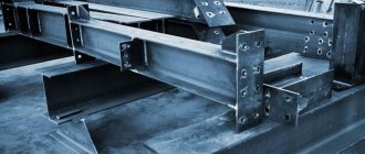
Drawings of metal structures
The manufacture of welded structures should be carried out in accordance with the requirements specified in the drawings on them. Drawings for welded metal structures have their own characteristics, so you need to be able to not only draw them up correctly, but also read them. To do this, it is necessary to study the symbols used on these design documents.
At the initial stage of development, general drawings are created, united by the name “KM”, which stands for metal structures. They indicate welding of structures in general form.
At the final stage, a set of “KMD” drawings is produced - detailed metal structures, which include all the drawings of each part involved in this type of connection. “KM” is the basis on which the drawings included in the “KMD” kit are developed. Providing “KM” is necessary in order to obtain permission to build a future facility. They will be used for future welding of building structures.
When drawing up drawings, you should be guided by the standards set out in GOST 2.410-68, which clearly outlines the rules by which drawings for metal structures should be made. High-quality assembly and welding of metal structures directly depend on competent drawing up of drawings. The general view gives an idea of what the structure should look like after welding.
The drawings contain technical data in special tables that serve as a guide for proper welding.
You need to start reading the drawings in a certain order. First, you should familiarize yourself with the first drawing of the kit to get a general idea of the work ahead. Then you need to familiarize yourself with the “list of elements”. For each part, called an element mark, it contains information about its section with a small sketch that can show individual dimensions, for example, a step.
The “Pos” column indicates the position number of the part in the drawing. Nearby in the “Composition” column there is an abbreviated designation of the profile that the section of the part has according to the rules of their symbolic designation in accordance with the requirements of GOST 2.420. Next come the columns that indicate the effort and grade of steel.
This app is required. The special significance of the statement lies in the fact that only it indicates in detail the names of the profiles, for example, “I-beam No. 14.” For such complex metal structures as trusses and gratings, a sketch will not be enough and separate drawings are produced for them.
A valuable detail for the welder in the general drawing may be an indication of the brand of electrodes that are recommended for installation and welding of metal structures. The drawings also conventionally show seams in accordance with the requirements of GOST 21.504-2005. The designation may include parameters such as seam length and leg size. Different types of seams use their own conventional images.
Information about profiles is placed on special callouts.
Next to the designation, information about the number of parts used in the design is placed through a dash.
This can be important when using a large number of similar parts, for example, on truss units.
REQUIREMENTS FOR BASIC MATERIALS
2.1. For welded metal structures of buildings, carbon and low-alloy steels are used in accordance with GOST 27772.
The chemical composition and mechanical properties of the main steel grades used for metal structures of buildings are given in Appendices 2 and 3.
2.2. Sheet and shaped rolled products arriving at the installation site must have a certificate from the manufacturer indicating the chemical composition and mechanical properties.
2.3. Incoming inspection of metal (sheets, rolled profiles) and structural elements of metal structures of buildings arriving at the enterprise for manufacturing, enlargement and installation includes:
checking the availability of a certificate or passport, the completeness of the data contained in it and the compliance of this data with the requirements of the standard, technical specifications, design or construction documentation;
checking the presence of factory markings and its compliance with certificate or passport data;
inspection of metal and structural elements to identify surface defects and damage that take the metal thickness beyond the minus deviations regulated by GOST 19903 and GOST 19904;
inspection and measurement (if there are appropriate instructions in the PDD) of structural elements (assemblies, blocks, trusses, rafters, etc.) to identify deformations that violate the geometric shapes and dimensions of structures specified in the design documentation.
2.4. In the absence of a certificate or incompleteness of the certificate data, the use of this metal can be allowed only after the necessary tests have been carried out to confirm that the metal meets all the requirements of the standard or technical specifications.
2.5. Incoming inspection of basic materials (metal and structural elements) is carried out by the organization that purchases these materials. The results of the incoming inspection must be transferred to the organization carrying out the manufacture or installation of structures.
Routing
This document serves as the welder's main assistant. The assembly of metal structures and their welding are complex processes that must be performed in a certain sequence. The technology for welding metal structures and its stages are described in detail in a special document called a technological map.
This document is included in the general design documentation. The development of a technological map is the responsibility of a process engineer who has a good understanding of the manufacturability of welded structures. The developer of the technological map makes the necessary calculations, on the basis of which the optimal parameters for connecting specific metal products are selected.
The technological map can cover various types of welded structures, including quite complex ones. These include, for example, welding of thick-walled structures. Such a map is indispensable when laying pipelines and installing bulky structures.
When welding metal of large thickness, with an increase in this size, for example, more than 15-20 millimeters, the volumetric welding stresses in the joints increase. This leads to the risk of cracks in the parts. To avoid this, it is recommended to weld in certain ways, for example, double layer or blocks. These recommendations are indicated in the technological map.
The technological map for the production of welded metal structures also includes rules for monitoring the resulting welded joints. Technological maps are divided into typical and standard. They must be carried out in accordance with existing regulatory documents.
The card for the installation of metal products indicates installation diagrams and the sequence of actions. The requirement for manufacturability is the possible location of the seams during welding - lower horizontal. A good option is to lay the seam “in a boat”.
Semi-automatic welding of metal structures is the most preferable. It is not practical to use fully automatic welding. In mass production, spot welding can be used. If you plan to apply sutures located at a close distance, then you cannot do this right away. You need to wait until the first seam has cooled and then start cooking the second. This will protect the metal from plastic deformation.
The technological map must be drawn up taking into account the available equipment. There is no single sample technological map. You can develop it yourself. However, this document must be created taking into account the requirements of existing regulatory documents in this area. The technological map is subject to mandatory approval by authorized persons. In addition to technical data, it can indicate labor costs.
A typical flow sheet may contain information on how reliable fixation of structural elements can be carried out, information on the possible need to heat up parts before welding, and data on welding parameters that must be set on the equipment used. If there are specific features of the technical process, they are described in detail.
Quality requirements must be confirmed by real figures of possible deviations. A separate section or paragraph may describe what actions he should take if unacceptable defects are detected.
In the technological map, a special section stipulates safety measures. Before work, the welder must familiarize himself with the contents of the technological map and follow its recommendations.
WELDING MATERIALS AND THEIR QUALITY CONTROL
3.1. Incoming inspection of welding materials
3.1.1. Welding materials must be inspected before use:
for the availability of a certificate (for electrodes, wire and flux) with verification of the completeness of the data contained in it and their compliance with the requirements of the standard, technical specifications or passport for specific welding materials;
for the presence on each packaging unit (pack, box, box, skein, coil, etc.) of appropriate labels (labels) or tags with verification of the data specified in them;
to ensure that there is no damage to the packaging and the materials themselves;
for the presence of a corresponding document regulated by the standard for gas cylinders.
3.1.2. In the absence of certificates for electrodes and flux-cored wire, it is necessary to determine the mechanical properties of butt welded joints made using these materials.
Welded butt samples should be tested for static tension, static and impact bending at a temperature of 20°C in accordance with GOST 6996 in the quantities indicated in table. 3.1.
Types of testing of welded joints in the absence of certificates
for electrodes and cored wire
| Type of test | Number of samples (not less) | Standardized indicator |
| Static stretch | 2 | Tensile strength - not less than the lower limit of tensile strength of the base metal, regulated by GOST |
| Static bend | 2 | Static bending angle, degrees, for steel thickness, mm. |
| carbonaceous - | ||
| up to 20, not less than 100 | ||
| St. 20, not less than 80 | ||
| low alloy - | ||
| up to 20, not less than 80 | ||
| St. 20, not less than 60 | ||
| Impact bending of weld metal | 3 | Impact strength - not less than the value specified in the technological documentation for field welding of this structure |
Indicators of mechanical properties are determined as the arithmetic mean of the number of tested samples.
If there is a discrepancy between the certificate data or test results (in the absence of a certificate) with the requirements of the relevant technical documentation, this batch of electrodes and flux-cored wire is not allowed for use.
3.1.3. If there is no certificate for solid welding wire or the data specified in it is incomplete, a chemical analysis of the wire is carried out, the results of which must meet the requirements given in Appendix 6. If the results of the chemical analysis are unsatisfactory, a re-analysis is carried out on a double number of samples, which is final.
3.1.4 If damage or deterioration of the packaging or the materials themselves is detected, the question of the possibility of their use is decided by the welding supervisor together with the quality control department (QC) of the enterprise (organization).
Classic technology for welding metal structures
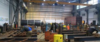
Welding is a unique method of producing permanent metal joints, which opens up wide opportunities for people to reduce the labor intensity of creating and installing metal structures.
It allows the use of rational types of sections in metal structures, which leads to a reduction in metal consumption by several times, compared with the use of other technologies.
Today, welding work is carried out using different methods, but all of them were created based on knowledge of classical technology. It is simple and can be implemented both for domestic purposes and on an industrial scale.
Welding angles for metal structures.
If you manufacture welding metal structures using classical technology, you will need to use the following energy sources:
- electric arc;
- gas flame.
Both options involve three methods for making welds:
Auto
Does not imply human intervention in the process of welding work. The welding machine is adjusted to the current operating mode, taking into account the specific type of operation being performed, only once before starting work.
Therefore, it is important to understand the main purpose of purchasing welding equipment when choosing in a store. Using the automatic mode, you can use resistance and electroslag welding.
Semi-automatic
When using this method, welds are formed manually, and electrodes are fed automatically. This state of affairs allows you to increase productivity without compromising the quality of the metal products created.
For semi-automatic welding, you can use gas flux, infusible electrodes, and welding wire.
Manual
All actions using the manual arc welding method are carried out by the welder without the use of automated equipment: from controlling the supply of the electrode to forming the connection itself.
Often, in manual mode, ordinary submerged arc welding, electric arc welding or soldering with a gas welding device are used. This method is rational to use for domestic purposes, and not in large-scale production, because it is excessively expensive and characterized by low productivity.
On a note! The semi-automatic method of arc welding of metal structures is most in demand in the domestic market. It is actively used in construction during the installation of reinforced concrete buildings, in mechanical engineering when designing cars, and also in everyday life.