Purpose of thread and its elements
The thread is the main element of the screw drive and threaded connection. It consists of a series of bulges and depressions on the torsion bodies, which provides a fastening that can withstand high loads. Cutting is used as a method of combining or compacting structural links.
The thread provides a fastening that can withstand high loads.
Its main elements are:
- internal, external and middle diameters;
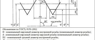
- profile is a cross section of a cut with a plane passing through the main axis of the part under consideration;
- profile angle - the angle formed by the sides of the profile;
- profile height is the length of the segment between the minimum and maximum cutting points in the cross-sectional plane of the axis in the direction orthogonal to the cutting guide;
- pitch - the length of the gap between two points of adjacent identical turns, measured parallel to the axis of the thread.
Main parameters and areas of application
The most common is metric thread, applied to the external and internal surfaces of a cylindrical shape. This is what is most often used in the manufacture of various types of fasteners:
- anchor and regular bolts;
- nuts;
- hairpins;
- screws, etc.
Conical-shaped parts, on the surface of which a metric type thread is applied, are required in cases where the created connection must be given high tightness. The metric thread profile applied to the conical surfaces allows the formation of tight connections even without the use of additional sealing elements. That is why it is successfully used in the installation of pipelines through which various media are transported, as well as in the manufacture of plugs for containers containing liquid and gaseous substances. It should be kept in mind that the metric thread profile is the same on cylindrical and conical surfaces.
Parameters of tapered metric thread
Types of threads belonging to the metric type are distinguished according to a number of parameters, which include:
- dimensions (diameter and thread pitch);
- direction of rise of turns (left or right thread);
- location on the product (internal or external thread).
There are also additional parameters, depending on which metric threads are divided into different types.
Internal metric thread
External metric thread
What is the image and designation of the thread
The designation allows, based on a combination of letters and numbers, to understand what type of cutting is presented for analysis. It includes: type, pitch and stroke, accuracy class and number of the corresponding standard. For a better understanding of the operation, an image is used - this is a drawing in which, in accordance with GOST, a structural element with a threaded surface is presented.
The diagram helps create a visual representation of the shape and geometric features of the carving.
Designation on drawings
When moving the contour of a flat figure (circle, triangle, trapezoid, etc.) along a spiral line, a cut appears on the surface of a given shape. The methods of its presentation in drawings are regulated in specially developed international documentation (GOST), which was created for an unambiguous interpretation of the designation of pain.
Image of external threads on shafts
The external cutting gauge appears throughout as a solid main line. In the image obtained by projection onto a plane parallel to the rod axis, the internal thread is indicated by a thin permanent line along its entire length. In a drawing with a projection of the orthogonal guide of the rod, the internal diameter of the thread should be depicted as a thin continuous arc constituting 3⁄4 of the main circle. If it is necessary to show the carving as invisible, then it is represented by identical broken lines along the internal and external diameter.
External thread on shafts.
Image of internal threads in parts holes
In the holes everything is different. The internal diameter of the thread is indicated by a continuous main line. In the image obtained by projecting onto the plane of the orthogonal axis of the rod, the external thread is shown as a thin permanent line. In the drawing with the projection of the orthogonal guide of the rod, the external diameter of the thread is represented by a thin continuous arc, which is 3⁄4 of the circle.
Internal threads in the holes of parts.
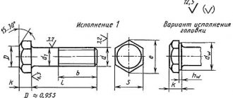
Symbol for metric thread (GOST 8724-2002)
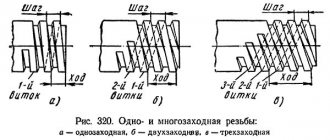
The definition of a thread includes the letter M (from the English metric system), the size of the gauge and the pitch of the thread, delimited by the sign “x”. Example: M8x1.25. It is possible not to specify a large step. Example: M8. If the thread is left-handed, then the letters LH are added. Example: M8x1-LH. The definition of a multi-start cut consists of the symbol M, the diameter, the sign “x”, the combination of Ph, the stroke, the symbol P and the pitch. For certainty, you can specify the number of visits.
This is interesting: How to clean copper at home from oxide, blackness and plaque
Metric thread (GOST 8724-2002).
Geometric parameters
Let's consider the geometric parameters that characterize the main elements of metric threads.
- The nominal thread diameter is designated by the letters D and d. In this case, the letter D refers to the nominal diameter of the external thread, and the letter d refers to a similar parameter of the internal thread.
- The average diameter of the thread, depending on its external or internal location, is designated by the letters D2 and d2.
- The internal diameter of the thread, depending on its external or internal location, is designated D1 and d1.
- The inside diameter of the bolt is used to calculate the stresses created in the structure of such a fastener.
- The thread pitch characterizes the distance between the crests or valleys of adjacent threaded turns. For a threaded element of the same diameter, a basic pitch is distinguished, as well as a thread pitch with reduced geometric parameters. The letter P is used to denote this important characteristic.
- The thread lead is the distance between the crests or valleys of adjacent threads formed by the same helical surface. The progress of the thread, which is created by one screw surface (single-start), is equal to its pitch. In addition, the value to which the thread stroke corresponds characterizes the amount of linear movement of the threaded element performed by it per revolution.
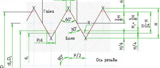
- A parameter such as the height of the triangle that forms the profile of the threaded elements is designated by the letter H.
Geometric parameters of the main metric thread profile
Table of metric thread diameter values (all parameters are indicated in millimeters)
Metric thread diameters (mm)
Complete table of metric threads according to GOST 24705-2004 (all parameters are indicated in millimeters)
Complete table of metric threads according to GOST 24705-2004
The main parameters of metric threads are specified in several regulatory documents.
This standard contains requirements for the parameters of thread pitch and diameter. GOST 8724, the current version of which came into force in 2004, is an analogue of the international standard ISO 261-98. The requirements of the latter apply to metric threads with a diameter of 1 to 300 mm. Compared to this document, GOST 8724 is valid for a wider range of diameters (0.25–600 mm). At the moment, the current edition of GOST 8724 2002, which came into force in 2004 instead of GOST 8724 81. It should be borne in mind that GOST 8724 regulates certain parameters of metric threads, the requirements for which are also specified by other thread standards. The convenience of using GOST 8724 2002 (as well as other similar documents) is that all the information in it is contained in tables, which include metric threads with diameters within the above range. Both left-handed and right-handed metric threads must meet the requirements of this standard.
GOST 24705 2004
This standard stipulates what basic dimensions a metric thread should have. GOST 24705 2004 applies to all threads, the requirements for which are regulated by GOST 8724 2002, as well as GOST 9150 2002.
This is a regulatory document that specifies the requirements for the metric thread profile. GOST 9150, in particular, contains data on what geometric parameters the main threaded profile of various standard sizes must correspond to. The requirements of GOST 9150, developed in 2002, as well as the two previous standards, apply to metric threads, the turns of which rise from the left upward (right-handed type), and to those whose helical line rises to the left (left-handed type). The provisions of this regulatory document closely echo the requirements given by GOST 16093 (as well as GOSTs 24705 and 8724).
Read also: DIY ripper drawings
This standard specifies the tolerance requirements for metric threads. In addition, GOST 16093 prescribes how metric type threads should be designated. GOST 16093 in its latest edition, which came into force in 2005, includes the provisions of the international standards ISO 965-1 and ISO 965-3. Both left-hand and right-hand threads fall under the requirements of such a regulatory document as GOST 16093.
The standardized parameters specified in the metric thread tables must correspond to the thread dimensions in the drawing of the future product. The choice of the tool with which it will be cut should be determined by these parameters.
Designation of thrust thread (GOST 10177-82)
The definition of a thrust thread must contain the letter S, the pitch and the value of the diameter. Example: S90-10. For left-sided cuts, additionally LH is indicated. If multi-pass cutting is considered, then its definition is made up of the symbol S, diameter, stroke and in brackets the letter P, the value of the step. Example: S80-20(P20).
Thrust thread (GOST 10177-82).
Designation of persistent reinforced thread (GOST 13535-87)
The definition of persistent reinforced cutting contains the letters S, as well as an angle of 45, caliber and pitch. Example: S45200-13. If the thread is left-handed, the letters LH are additionally indicated. If it is necessary to define a multi-start thread, then indicate the letter S, the angle 45, the diameter, the stroke and the symbol P along with the pitch value, highlighted in brackets. Example: S4520024(P12) - two-start, stroke value 24 mm, pitch - 12 mm. For left-sided cuts, additionally LH is indicated.
This is interesting: Metal turning. Features of the process and necessary equipment
Reinforced thrust thread (GOST 13535-87).
Trapezoidal thread
Profiles and thread sizes
(GOST 9484-81)
The standard applies to trapezoidal threads and establishes the profiles and dimensions of its elements.
BASIC PROFILE of external and internal threads
An example of a symbol for a trapezoidal single-start thread with a nominal diameter of 20 mm, a pitch of 4 mm and a tolerance field of average diameter 7e:
Tg 20 x 4 -7e NOMINAL PROFILES of external and internal threads h3 - height of the external thread profile; H4 - internal thread profile height; d3 - internal diameter of the external thread; D4 - outer diameter of the internal thread; R1 - rounding radius at the top of the external thread; R2 is the radius of torsion in the root of the external and internal threads; ac is the clearance at the top of the thread. DIAMETERS AND STEPS of trapezoidal single-start threads according to GOST 24737-81
Preferred diameters and pitches are specified in GOST 24738-81.
Numerical values of tolerances for diameters and pitches - according to GOST 9562-81 DIAMETERS AND STEPS of trapezoidal multi-start threads according to GOST 24739-81
Notes: 1. Steps highlighted by a frame are preferred. 2. The steps indicated in parentheses are not recommended for use when developing new designs. 3. Threads with a stroke value marked * have a lead angle of more than 10o. For these threads, the deviation of the profile shape must be taken into account during manufacturing. 4. In technically and economically justified cases, it is allowed to use other values of nominal thread diameters in accordance with GOST 24738-81. 5. When choosing thread diameters, you should prefer the first row to the second.
An example of a symbol for a trapezoidal multi-start thread with a nominal diameter of 20 mm, a stroke value of 8 mm, a pitch of 4 mm and a tolerance field of 8e:
Tg 20-8 (P4) - 8e
The same, left-handed:
Tg 20-8 (P4) LH - 8e
Make-up length , if it differs from the thread length, indicate in millimeters at the end of the thread designation, for example:
Тг 20-8 (Р4) LH - 8е - 180
Numerical values of make-up lengths related to groups N and L - according to GOST 9562-81.
The fit in a threaded connection is designated by the fraction
Tg 20-8 (P4) LH - 8Н/8е - 180
Numerical values of tolerances for diameters d and D1 - according to GOST 9562-81.
Numerical values of tolerances for diameters d2, d3 and D2 are in accordance with GOST 24739-81. Application of trapezoidal thread
The trapezoidal thread of a screw is a running thread that has a relatively large friction force and is self-locking. The advantage for lifting technologies is that in the resting position it does not require additional fixation.
Trapezoidal threads are used to convert rotary motion into linear motion and are used primarily for linear motion. It also finds its use as a lead screw in lathes or as a drive thread for screw presses on tables or vehicle bridges.
Application examples for trapezoidal spindle threads:
— feed movements on machine tools (for example, adjusting and lead screws); — movement on the manipulator; — regulation of movement on lifting mechanisms and forklifts; — movement of the shutter when locking injection molding machines; — moving movement on assembly containers; - vertical movement when working with the press.
Related documents:
GOST 3469-91 - Microscopes. Lens thread. Dimensions GOST 4608-81 - Metric thread. Interference fits GOST 5359-77 - Ocular threads for optical instruments. Profile and dimensions GOST 6042-83 - Edison round thread. Profiles, dimensions and maximum dimensions GOST 6111-52 - Conical inch thread with a profile angle of 60 degrees GOST 6211-81 - Conical pipe thread GOST 6357-81 - Cylindrical pipe thread GOST 8762-75 - Round thread with a diameter of 40 mm for gas masks and calibers for her. Main dimensions GOST 9000-81 - Metric thread for diameters less than 1 mm. Tolerances GOST 9484-81 - Trapezoidal thread. Profiles GOST 9562-81 - Single-start trapezoidal thread. Tolerances GOST 9909-81 - Tapered thread of valves and cylinders for gases GOST 10177-82 - Persistent thread. Profile and main dimensions GOST 11708-82 - Thread. Terms and definitions GOST 11709-81 - Metric thread for parts made of plastic GOST 13535-87 - Reinforced thrust thread 45 degrees GOST 13536-68 - Round thread for sanitary fittings. Profile, main dimensions, tolerances GOST 16093-2004 - Metric thread. Tolerances. Clearance fits GOST 16967-81 - Metric threads for instrument making. Diameters and pitches GOST 24737-81 - Single-start trapezoidal thread. Main dimensions GOST 24739-81 - Multi-start trapezoidal thread GOST 25096-82 - Persistent thread. Tolerances GOST 25229-82 - Metric conical thread GOST 28487-90 - Conical locking thread for drill string elements. Profile. Dimensions. Tolerances
Necessary cutting tools
Cutting is widely used in everyday life and in production, so tools for making cutting are widespread. There are several types of cutting devices:
- Thread cutters are multi-toothed tools in which the thread cutting process is more productive than the cutters. They are divided into cylindrical comb, disk, prefabricated comb, heads for high-speed milling.
- Dies are a multi-edged tool for creating external cuts. There are round, solid, sliding devices, and split dies.
- Threading heads are special products for cutting internal and external threads and have a number of advantages compared to round dies. Depending on the comb design, heads are available with round radial, flat tangential and flat radial dies.
- Taps are an axial tool consisting of several blades designed for cutting internal threads. The following types are distinguished: manual, machine, wrench, machine, master, etc.
- Thread cutters are a tool for precise machine cutting of internal and external threads. They are divided into rod, single-strand and multi-strand shaped.
Making threads
To obtain inch cuts, 2 main methods are used:
- Knurling;
- Slicing.
Rolled ones are made using special thread rolling rollers, the profile of which follows the contour of the thread. The workpiece is placed between the rollers, and the threads are rolled to the required dimensions.
Threads made using this method have higher mechanical characteristics due to a smoother distribution of stress waves between the turns. Also, knurling has high productivity, which has allowed it to be widely used in mass production.
The disadvantage of the rolling method is the difficulty of making rollers. Their accuracy must be at a high level. Otherwise, it is very difficult to guarantee the required thread sizes. The second point is the material of the rollers. It must have improved mechanical properties. Typically, high-alloy stamped steels are used for this. All this makes the knurling method very expensive from a financial point of view.
Cut threads are easier to manufacture, but in terms of mechanical properties, especially the endurance limit, they are noticeably inferior to rolled threads. This is due to the presence of sharper profile edges and, accordingly, a higher stress coefficient.
The product is cut in two ways:
- Manually.
- Using a lathe.
When cutting manually, a tap (for internal cutting) and a die (for external cutting) are used. The pipe is clamped. One of the indicated types of available tools is put on and screwed onto its end, depending on the type of thread. Carry out cutting. This process is repeated to improve purity and accuracy.
On a lathe, the algorithm of actions is quite similar. Only the pipes are clamped not in a vice, but in a machine chuck. Next, the cutter is brought in, the thread feed is turned on, and the machine begins the manufacturing process. This method is more effective compared to manual cutting, but requires certain qualifications from the turner.