Development of the surface of a straight annular helical conoid
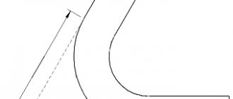
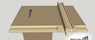
Let us consider a straight helicoid, which is formed by the movement of a rectilinear generatrix NM
along two guides (a cylindrical helix and its axis), and in all positions the generatrix makes a right angle with the axis and remains parallel to the plane of parallelism (in Fig. 1 - the horizontal plane).
An approximate development of one turn is part of a flat ring enclosed between two concentric arcs (Fig. 2).
Picture 1
Figure 2
Length L
the major arc is equal to the length of one turn of the outer helix;
the length l
of the smaller arc is equal to the length of the turn of the internal helix.
The arc radii R 1 and r 1
and the cut angle
α
can be determined graphically and analytically.
Analytical method
Let us denote the width of the helical surface b, with b = Dd/2
Formula 1
Since helical lines unfold into two concentric arcs at the same central angle, and such arcs are related to each other as radii, then
Formula 2
Cutting angle α
determined from the proportion:
Formula 3
Graphic method
Values r 1
,
R 1
and
α
can be determined graphically (2 Fig.b).
We construct right triangles ABC
and
ЕВС
, in which the leg
BC = s = 48
mm, and
the legs AC
and
EC
are equal to the lengths of the circles
πD
and
πd
.
The quantities πD and πd
are calculated or determined by the following construction: draw a straight line
Oa
(b - lower right figure) at an angle of 30° to the vertical diameter until it intersects at point a with the tangent passing through the lower end of the same diameter. From point a we plot the length of three radii on a tangent and connect the resulting point b to the upper end of the diameter. Segment bc is equal to half the circumference.
The hypotenuses of the constructed triangles express the lengths of the unfolded helical lines L
and
l
.
To construct the length r 1
, we lay off on
AB
from point
A
the segment
AF = l
and from point
B
the segment
BC = b
.
We connect points F
and
E
with a straight line
E
F and through point
K
draw a straight line
KN || EF
until it intersects
BE
at
point
N. Then the segment BN = r 1 = 14 mm
.
(Indeed, from the similarity of triangles BEF and BNK
it follows that BN/BE = BK/BF. But
BN = r 1, BE = l, BK = b; BF = L - l
. Hence r
1 = bl/(L - l )
.
Radius R 1 = r 1 + b = 14 + 15 = 29
mm.
It can also be found directly by construction, if through the point N
we draw a straight line
NM ||
AC until it intersects with
AB
.
Then segment BM = R 1 = 29 mm.
To construct the cutout angle α, we plot on a circle of radius R 1 the difference between the circumference 2π R 1
and arc length
L
equal to 18 mm, and connect the ends of the deferred arc to the center.
For large values of D, d and s
It is difficult to carry out the above-described constructions in full size. In this case, you should use the analytical method or perform constructions on a reduced scale, which reduces the accuracy of the result.
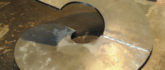
Having cut out the required number of individual turns from the sheet, you can form a helical surface from them. To attach turns to the surface of a cylinder with diameter d, a helical line of a given pitch s is drawn on the latter. The methods of connecting and connecting the turns depend on the technology adopted.
Development of the surface of a straight helical conoid of variable width
In this case, the internal guide helical line is located on the cone, the width of the conoid surface continuously changes from the maximum value b to the minimum value b1.
Figure 3
The horizontal projection of the outer helix (cylindrical) is a circle, and the projection of the inner helix (conical) is the Archimedes spiral.
To construct a scan, the values of R 1 and α
(formulas 1 - 3).
Draw a circle with radius R 1
and mark the central angle α on it.
The resulting arc, the length of which is equal to L
, is divided into several equal parts (in Fig. 3 by 12) and radii are drawn through the division points.
On the radii, the lengths of segments 0 - 01 are plotted sequentially ;
1 - 11; 2 - 22 , etc., taken from a horizontal projection, where they are depicted in life size.
Thus, a number of points are obtained - 11;
21; 31;…121 , connected by a smooth curve.
Calculation of the feather of a screw conveyor or auger
For KOMPAS-3D
the task is greatly simplified because there is a free library called
“Auger Feather” that does everything for you.
All you have to do is enter the initial data and get a finished drawing or 3D model. I understand that a freebie dilutes the brain, but it significantly reduces the time spent. As a result, you will have something similar. We fill out the format, add a couple of technical notes. and these requirements are issued for production.
“Auger Feather” library is freely available and can be downloaded on the Internet. By the way, it fits all versions of KOMPAS-3D, including the latest one. Copy the files to the folder with the libraries ASCON/KOMPAS-3D V16/Libs/
and connect it. Otherwise, you will have to calculate everything yourself.
So.
Given
.
For a screw conveyor with a diameter D
with a given shaft diameter
d
and pitch
S
(Fig. a), it is necessary to produce feathers of sizes
Do, do
and
αо
(Fig. b).
Being stretched on a shaft of diameter d
at a given pitch
S ,
they should form a screw with diameter
D. To do this, it is necessary that Do and do, respectively, be slightly larger than D and d, since when the feather winding is stretched, their diameter decreases somewhat.
Length of arcs L and l
expressed through their radii and angle (rad):
L = α·Do/ 2; l = αdo/ 2;
Hence:
Do = 2·L / α do = 2·l / α
When winding feathers onto a shaft, these arcs form helical lines: arc I along the shaft with a diameter d, and arc L along an imaginary cylinder with a diameter D equal to the diameter of the screw.
The development of a helix can be represented in the form of a right triangle, in which one leg is equal to the pitch S, and the other is equal to the length of the circle on which the helix is wound, i.e. πD (Fig. c).
Thus, we can write the following dependencies:
l = √S² + (πd)² L = √S² + (πD)²
With sufficient accuracy for calculation D - d = Do - do, since both parts are approximately equal to 2d.
Substituting the values of these parameters, we get D - d = 2L / α - 2 l / α
From here
α = 2(L - l) / D - d
Knowing α, L and l, we find Do and do using the above formulas
The value of αo (deg) will be
αo = (2π - α)·57.3
Thus, you can find the necessary dimensions Do, do n αo to make a template from which feathers can be made for this screw conveyor. To connect the feathers to each other, an allowance of 5...10 mm should be made at their ends, depending on the method of connecting them.
Cone augers are usually used to compact the transported material, therefore, they are mainly made cast, where the cone angle and the change in the pitch of the turn are set. If made from sheet metal, a scale model is first created. You can use the method of integrating the contour of the pen, which is easier for others.
For whom this information is not enough, for example, you need to select the optimal screw parameters, find the book by A.M. Grigoriev. Screw conveyors
M., "Mechanical Engineering". 1972, 184 pp.
The book discusses examples of the use of screw conveyors, features of their operation and the methods used for their calculation. The theory of motion of an isolated material point in a screw conveyor and recommendations for extending this theory to a continuous flow of transported material are presented. New analytical calculation methods and examples of designing high-performance and economical screw conveyors are given. The book is intended for engineering and technical workers involved in research, calculation, design, production and operation of conveyors.
Or a foreign book : Technology of manufacturing auger spirals. Gevko B M
- Lvov: Vishcha school Publishing house at Lvov, university, 1986. - 128 p. The monograph describes a new technology for forming screw spirals using the method of cold winding, rolling and stamping. This technology helps to increase the accuracy of processing parts, reduce the material consumption of products, and increase labor productivity in mechanical engineering and instrument making. The author's developments have been introduced into the standards of the Ministry of Tractor and Agricultural Engineering and are used at industry enterprises.
There are of course other books. “Joke”, as the author of the latter would say...
Development of the surface of an oblique helical helicoid
In this case, each generatrix of the surface remains parallel to the corresponding generatrix of some coaxial cone of rotation with an apex angle equal to 2α
, which is called the guide cone.
Figure 4
Graphic method
To construct a development of one turn of a given surface, divide the horizontal projection into equal parts (for example, 12) and take each of them as an isosceles trapezoid.
The sides of all trapezoids are equal. Their natural size is given by the frontal projection 0′ – 0'1 = b
- surface width.
The value of b can be calculated using the formula b = R - r/sinα
.
Two other sides, for example 0 - 1 and 01
- 11, are equal to
1/12 L and 1/12 l
, where
L and l
are the lengths of one turn of the outer and inner helical lines.
To construct a trapezoid, you also need to know the length of its diagonal, for example 0 - 11
.
Having determined by any known method the true length of the diagonal from its projections ( 011 and 0'1'
1), we construct an approximate development, as a series of equal triangles adjacent to one another (Fig. 4, b). Each triangle is constructed using three known sides. Then the vertices of the triangles are outlined with a smooth curve.
Analytical method
Based on the bending of the surface of an oblique helicoid into a single-sheet hyperboloid of revolution, the surface of which is then replaced by a truncated circular cone. The dimensions of the sweep of one turn (Fig. 4, c) are determined by the formulas:
Formula 4
Development of a helical surface of variable pitch
In the examples discussed above, the external and internal screw guides of these surfaces had the same pitch. To increase the angle of elevation of the external screw guide, its pitch is increased. Thus, the screw guides in this case have different pitches S and s, and the surface itself is called a variable pitch helical surface.
In Fig. Figure 5 shows projections of ¼ full revolution of such a helical surface. One end of the generatrix moves along a helical line of pitch S and radius R, and the other - along a helical line of pitch s and radius r.
In this case, the angle at which the generatrix intersects the vertical axis no longer remains constant and the segments of the generatrix enclosed between the guides are also not equal to each other. The minimum length of these segments is l0 = 001 = R - r
;
the maximum (l4) is equal to the hypotenuse of a right triangle, one leg of which is the frontal projection 4′ - 4'1,
and the other is the horizontal projection of the same segment, i.e.
Figure 5
The construction of an approximate development for ¼ of a full turn was carried out in the same way as in the previous example, but in this case it is necessary to determine the true length of each side of the surface compartments replaced by trapezoids and each diagonal. This is done in Figure 5 by constructing right triangles using techniques known from descriptive geometry.
As for the other two sides of all compartments, they, as in the previous example, are equal to L/n
and
l/n, where n
is the accepted number of divisions of one turn of the screw guides (in this case
n = 16
).
The values of L and l
are determined as indicated above (using formulas 2).
Based on materials: “Technical developments of sheet metal products” N.N. Vysotskaya 1968 “Mechanical Engineering”
Send your good work in the knowledge base is simple. Use the form below
Students, graduate students, young scientists who use the knowledge base in their studies and work will be very grateful to you.
Posted on https://www.allbest.ru/
Calculation and construction of auger spiral development
1.
Calculation of the reaming from a screw spiral with a constant pitch
H - spiral pitch;
D 0 - outer diameter of the screw spiral;
d 0 - internal diameter of the screw spiral;
D is the outer diameter of the screw spiral;
d is the internal diameter of the screw spiral;
b - cutout angle of the auger spiral;
2.
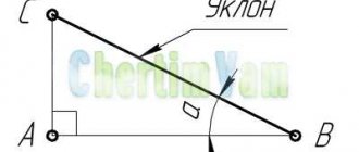
Construction of a screw spiral with a variable pitch in a geometric progression.
You can build a conical spiral with a certain slope where
Everything is typed in Microsoft Office Excel and constructed in KOMPAS-3D using a spline.
3.
Calculation of the development of a screw spiral with a variable pitch according to geometric progression.
It is calculated from certain angles (radians) with a set interval to construct the development. For convenience, you can type Microsoft Office Excel.
I couldn’t integrate this function for counting on a certain interval from, so I did it in a graphic-analytical way, where I inserted a ready-made template: “Sqrt (315^2+(200/2/PI*(1 - (1/1.1)^(x /2/PI))/(1-1/1.1))^2)/(315-250)*(1-Sqrt((2*PI*250)^2+(200*(1/1.1)^( x/2/PI-1))^2)/Sqrt((2*PI*315)^2+(200*(1/1.1)^(x/2/PI-1))^2))", Where
After constructing the graph, the abscissa is divided into intervals (radians) in accordance with the calculated sweep radii. Determine the areas of intervals limited by the function. The areas S1, S2..., are the values of the opening angles (radians) between
spiral screw reamer
Posted on Allbest.ru
Similar documents
- Technical considerations before manufacturing the “Auger Finger” part: dimensional accuracy, part material and its chemical and mechanical properties; analysis of manufacturability and design, clear and complex assessment. Type of production, method of acquisition, possession.
course work, added 03/13/2011
Description of the drive design. Calculation of gearbox gears. Determination of permissible contact stresses and bending stresses. Determination of the main parameters of cylindrical gears. Check calculation of bearings on high-speed and low-speed shafts.
course work, added 12/19/2011
Determination of reamer material by markings. Measuring the angle of the cutting part using a Babchinitser goniometer. A list of tool properties that are ensured by uneven tooth spacing. Calculation of cutting conditions and time for processing a hole.
practical work, added 01/25/2015
Design and calculation of a cutter for processing gears. Development of a combined reamer for hole processing. Calculation and design of a broach for processing a splined bushing. Floating chuck for mounting a combined reamer.
course work, added 09/24/2010
The main purpose of the dosing device. Method for calculating the grain metering screw, optimizing its design and technological parameters. Simplified classification of dispensers according to the structure of the operating cycle, design features, economic requirements.
course work, added 05/01/2010
Axial cutting tools, reamers, their types, features of their designs, classification. Forms of sharpening twist drills. Features of deep drilling. Purpose of tolerances, main reasons for breakdown. Requirements for the accuracy of conical holes.
test, added 05/23/2013
Preferred numbers and their patterns. Streamlining the selection of values and gradations of production process parameters. Advantages and disadvantages of series of numbers constructed according to a geometric progression. Programs and plans for comprehensive standardization.
abstract, added 06/06/2011
Synthesis of the cam mechanism. Constructing a diagram of the speed, displacement, acceleration of the pusher. Plotting a graph of changes in pressure angle. Synthesis of involute gearing. Calculation of the mass and geometric parameters of the flywheel, plotting graphs.
course work, added 01/05/2013
Technological analysis of the part design. Drawing up options for a part manufacturing plan and choosing the most appropriate one. Determining the dimensions of the part development. Calculation of strip for blank cutting. Calculation of material spring parameters.
course work, added 08/13/2012
Scope of application and modern designs of electric frying pans. Design, principle of operation of an electric frying pan with direct heating, its thermal calculations. Determination of the main structural dimensions of the frying pan, calculation of the spiral.
Development of the surface of the screw turn
The development of the surface of a straight annular helical conoid can only be performed approximately, because this surface is not developable even theoretically. The length of the conoid arc, which is directly located on the cylindrical surface, and the outer arc of this surface are divided into a certain number of segments. Through every two points of the outer arc of the conoid and the inner arc located on the surface of the generatrix of the cylinder and the axis of the cylinder, lines are drawn that divide the surface of the conoid into sectors; the more sectors there are, the more accurate the construction of the scan will be. The natural lengths of all segments of sectors are determined using descriptive geometry methods. The author tried to calculate the lengths of all segments of one of the sectors of the auger reaming surface theoretically. To calculate the development, data was taken from the topic post: Outer diameter: D=125mm; Inner diameter: d=22 mm; Step: H=60mm. For calculation, the circumference of the generating cylinder and the outer one, as well as the inner and outer helical lines, were divided into 12 parts, i.e. the surface of the conoid was divided into the specified number of sectors. All constructions of the design scheme are shown in the figure:
All calculation formulas used for the calculation are shown below.
All calculations of angle values were performed in radians, only at the end of the calculation of angle values. As a result of the calculation, the following scan was obtained:
As a result of constructing the scan, the following results were obtained: The length of the outer arc of the conoid is equal to: L=396.56 mm; Internal arc located on the generating cylinder: l=91.84 mm; External reaming diameter: D=133.68 mm; Reamer internal diameter: d=30.69 mm. Reamer cutout angle: 20.59 degrees. At the same time, for comparison, I made a calculation using the existing method: https://razvitie-pu.ru/?page_id=4440
As a result of the calculations, I received the following results: The length of the outer arc of the conoid is equal to: L=397.256 mm; Internal arc located on the generating cylinder: l=91.525 mm; External reaming diameter: D=133.808 mm; Reamer internal diameter: d=30.808 mm. Reamer cutout angle: 19.794 degrees. The results converge perfectly, the only difference is that the center of the sector cut, the calculated angle of development, the existing method is in the center of the internal diameter of the development, and the one I built is close to the center of the diameter of the generating cylinder.
1. Required screw diameter (m)
where Q
- calculated conveyor productivity [see. (5.1)], t/h;
k
D
is the ratio of the screw pitch to its diameter: for abrasive materials
k D
= 0.8, for non-abrasive materials
k D
= 1.0;
n in — screw rotation speed, min -1; preliminarily accepted according to the table. 13.2, then checked using formula (11.2) and agreed with GOST 2037-82 (see paragraph 11.2);
ψ - gutter filling coefficient (Table 11.3);
ρ—bulk density of cargo, t/m3;
k
β
is the coefficient of productivity reduction depending on the angle of inclination of the conveyor (Table 11.4).
The screw diameter must be checked using formula (13.1) and consistent with the data in table. 11.1.
2. Required power on the propeller shaft (kW)
Р
0
= 0.0027Q (
L
g
w ± Н),
(11.4)
where L
g—length of the horizontal projection of the conveyor, m;
w
— coefficient of resistance to cargo movement (see Table 11.3);
H - height of lifting (plus) or lowering (minus) of the load, m.
3. The motor power to drive the screw conveyor is determined by formula (8.21). In this case, the safety factor is taken to be K = 1.25.
4. The required gear ratio between the motor shaft and the propeller shaft is determined by formula (8.23).
5. The actual transmission ratio of the conveyor drive is determined after clarifying the kinematic diagram of the conveyor.
6. Actual propeller speed (min -1)
where n is the engine shaft rotation speed, min -1;
u f is the actual gear ratio of the drive.
The actual propeller rotation speed should not differ from the nearest rated frequency according to GOST 2037-82 by more than 10%.
7. Actual conveyor capacity (t/h)
where S is the screw stroke, m: with a single-thrust screw S
= t
(
t
is the pitch of the screw), with a double-threaded screw
S = 2 t .
If the actual productivity differs from the calculated one by more than 10%, the conveyor is recalculated.
8. Torque on the propeller shaft (Nm)
T 0 = 9550R 0 /. (11.7)
9. Axial force on the screw (N)
(11.8)
where k is a coefficient taking into account that the force is applied on the average diameter of the screw: A = 0.7...0.8;
D
— screw diameter, m;
α is the helix angle of the propeller;
β is the angle of friction of the load on the screw - see formula (4.8) and table. 4.1.
10. Lateral load (N) on the section of the screw between two supports
(11.9)
where l
— distance between propeller shaft supports, m;
L
— total length of the propeller shaft, m.
11. The screw shaft is considered as a split shaft and is calculated for torsion by moment T 0 , tension or longitudinal compression by force F OC , bending from a distribution along the length l
transverse load F p o p ep and bending under the influence of its own weight at length
l
.
The deflection of the screw should not exceed 40% of the gap between the screw and the groove.
Developments - general information.
1. General information about sweeps. Reaming is the process of machining holes to achieve improved cleanliness and accuracy. A reamer is a multi-toothed tool that, like a drill and a countersink, during processing rotates around its axis (the main movement) and moves forward along the axis, making a feed movement. Reaming allows you to obtain a hole of the 2-3rd class of accuracy and 7-8th class of cleanliness of the machined surface. 2. Design of reamers. 2.1. Basic structural elements of reamers. Manual and machine reamers (Fig. 1) have the following main parts: working, cutting, calibrating, neck, shank. The purpose of the neck and shank of reamers is the same as that of drills and countersinks. The working part includes cutting and calibrating parts and a guide cone, which serves to protect against damage and facilitate the entry of the reamer into the hole.
Rice. 1. Elements of a) machine and b) manual reamers. The cutting (taking) part of the reamer is a cone, on the surface of which teeth are formed. The calibrating part consists of a cylindrical section and a section with a reverse taper. The front and rear surfaces of the reamer teeth, both on the cutting part and on the calibrating part, are flat. 2.2. Structural elements of the reamer: D – diameter of the reamer; Z – number of teeth; 2φ – angle of the cutting part; interdental grooves, their shape and uneven distribution; tooth profile, α and γ – rear and front angles on the cutting part, rear cone, reamer fastening elements; L is the total length of the sweep. 2.2.1. The diameter of the reamer is the most important structural element, since ultimately the purpose of the reamer is to produce an accurate round hole of certain dimensions. When assigning the diameter of the reamer, it is necessary to take into account the breakdown; reserve for wear; tolerances for the manufacture of the reamer itself. To ensure entry into the hole, the small diameter of the cutting part is made smaller than the diameter of the machined hole by 1.3-1.4 allowances for reaming. The diameter of the reamer at the end of the cutting part and at the cylindrical section of the calibrating part is selected depending on the breaking of the hole during processing, the tolerance for making the hole and the desire to provide the maximum possible margin for wear of the reamer along the diameter. The layout of the tolerance fields for the diameter of the reamer is shown in Fig. 2. The diagram is shown for the case when, during the reaming process, the diameter of the hole increases compared to the actual dimensions of the reamer. Therefore, in order to obtain a hole within the tolerance range, the maximum reaming diameter is taken to be equal to the maximum hole diameter minus the maximum breaking value. The tolerance on the reamer diameter must be chosen so that its provision on grinding and finishing machines does not present any particular difficulties. The amount of hole breaking depends on the size of the workpiece being processed, cutting conditions, the accuracy of manufacturing the reamer and the accuracy of its installation on the machine, etc. In some cases, especially when processing thin-walled parts made of materials with increased ductility and viscosity with worn reamers, a negative effect may be observed breaking the hole. When designing reamers, the approximate maximum value of hole breaking is assumed to be equal to 1/3 of the tolerance for the hole. The specified values for the hole breaking value are determined experimentally.
Rice. 2. Layout of tolerance fields for the diameter of the reamer. The diameter at the end of the calibrating part is taken to be less than the diameter of the reamer. The result is a reverse cone. It is generally accepted that the reverse cone on reamers serves to reduce the friction of the reamer on the machined hole, facilitate the withdrawal of the reamer and protect the hole from breaking. For manual reamers, the reduction in diameter towards the shank is 0.010 - 0.015 mm. Due to such a small amount of thinning, the cylindrical section of manual reamers is often not made, and the reverse cone begins immediately after the cutting part. 2.2.2.Number of teeth . The number of reamer teeth is selected depending on the material being processed, the diameter and design of the reamer. As the number of teeth increases, the cleanliness of the holes is improved, but the cross-section of the chip flutes decreases, and they may not be sufficient for free placement and removal of chips. With a large number of teeth and a shallow groove depth, regrinding reamers to smaller sizes becomes difficult. Despite the removal of small layers of metal, the reamers have a relatively small number of teeth (from 6 to 14) for entire machine and hand reamers with a diameter of 3-50 mm. Reamers of a prefabricated structure are made with a smaller number of teeth, since the fastening elements of the insert teeth require adequate space for their placement. Reamers usually have an even number of teeth. This makes it easier to measure their diameter. The uneven distribution of teeth around the circumference has a positive effect on the operation of the reamer, which helps dampen vibrations that occur during operation, especially at increased cutting conditions in conditions of insufficient rigidity of the AIDS system, and improves the cleanliness of the machined surface. To make the final selection of reamer teeth, it is necessary to draw the resulting tooth and groove profile. In reamers with helical teeth, the number of teeth is chosen to be smaller. Depending on the properties of the material being processed and the type of chips being separated, a different number of teeth can be selected. For reamers intended for processing ductile metals, the number of teeth is determined by the formula z = 1.5 root of D + 2 ; for brittle metals z = 1.5 root of D + 4 . 2.2.3. The rake angle γ of the reamers is usually taken equal to zero, since the reamer operates in the zone of small thicknesses of the cut layer, the nature of the cutting process depends mainly not on the rake angle, but on the radius of curvature of the cutting edge. On rough reamers and when processing viscous materials, the rake angle is 5-10°. 2.2.4. The clearance angle is taken small to maintain the strength of the cutting edge. If the clearance angle is taken to be significant, the strength of the edge is reduced and chipping is possible, leading to deterioration in the cleanliness of the hole surface. The sweep ranges from 4-8°. For finishing reams, the angle α is chosen less than for rough reams. 2.2.5.Ribbon width along the cylinder . The teeth on the cutting part are sharpened “to the point”, and on the calibrating part - leaving a cylindrical strip 0.05-0.3 mm wide. When processing viscous metals, in order to avoid sticking of metal particles, the width of the ribbon is reduced to 0.05–0.10 mm. The tape serves to guide the reamer in the hole, facilitates calibration of the hole and facilitates control of the reamer along the diameter. 2.2.6. Plane angle φ. The operation of the reamer is greatly influenced by the angle φ between the reamer axis and the cutting edge, which, with a rake angle equal to zero, runs along the generatrix of the cone of the cutting part. With a change in the angle φ, the relationship between the width and thickness of the cut, the components of the cutting force, and the intensity and nature of tool wear changes. As the angle of the intake cone increases, the axial force increases, making it difficult to advance the reamer. Therefore, for manual reamers, the lead angle is assumed to be small, which also contributes to the smooth entry and exit of the reamer from the hole. Based on experimental data for manual reaming when processing through holes φ = 1 ÷ 2°. During operation, machine reamers are guided better than manual ones, so the length of their cutting part can be shorter and the lead angle larger. When processing cast iron φ = 4÷5°, and when processing steel φ = 12 ÷ 15°. For blind holes, both manual and machine reamers, φ = 45 ÷ 60°. For machine reamers, the value of thinning ranges from 0.04–0.10 mm, with the length of the calibrating part equal to 0.25–0.30 times the diameter of the reamer. On the basis of research and production experience, in recent years, reamers have been developed with a sharply shortened reverse cone length to 3-5 mm and a reduction in diameter at the rear end by 0.5-0.7 mm, which provide the required accuracy and high surface frequency especially when machining short holes. 2.2.7. Profile angles . Processing of chip grooves of reamers is carried out with single-angle (Fig. 3, a) or double-angle (Fig. 3, b) cutters with a profile angle θ = 65 ÷ 110°. For medium and large sizes, a profile with a radial outline of the tooth wall is used, which facilitates the placement of chips in the grooves (Fig. 3, c).
Rice. 3. Reamer groove profiles. When milling, obtaining an uneven pitch with the same tooth width is ensured by changing the depth of the groove by appropriately setting the cutter. Typically, the grooves of reamers are made straight, which simplifies their production and control. For processing holes that are interrupted in length or have longitudinal grooves, reamers with helical teeth are indispensable. Reamers for processing light alloys are also equipped with helical grooves. The angle of inclination of the screw teeth in reamers can reach up to 30-45°. The direction of the screw grooves is made opposite to the direction of rotation of the reamer in order to eliminate self-tightening and jamming of the reamer in the hole. The use of reamers with a large angle of inclination of the helical groove ensures good cleanliness of the machined surface, but at the same time significant feed forces arise. 2.2.8. The length of the working part of the reamer and its total length. The length of the working part and the total length of the reamers are taken according to the relevant standards, and the total length of the reamer depends solely on the depth of the reamed holes and the method of fastening the reamer. If the reamer must have a guide part, then it is necessary to include the length of the guide part in the total length of the reamer. It is recommended to make the length of the working part of the reamer within 0.8 - 3 times the diameter of the reamer. The shorter the working part of the reamer, the easier the reamer cuts, but because of this, the direction of the reamer in the hole and the cleanliness of the surface of the holes sharply deteriorate. If the direction of the reamer in the hole is good (the presence of a guide part), you can reduce the length of its working part. There are disk reamers, which are discs with teeth with a width equal to 0.1 - 0.2 of the diameter of the reamer, mounted on a mandrel with a guide part. 2.2.9. Reamer fastening elements . The reamer is equipped with a connecting part. Mounted reamers most often have a tapered hole with a taper of 1:30 and an additional end keyway. Shank machine reamers have a conical shank with a foot, which is inserted into the corresponding socket of the spindle or a special chuck, or a cylindrical shank. Using hand reamers, a square is made at the end of the shank for working with a crank. Thanks to the hinged connection, the oscillating chuck allows you to compensate for the mismatch between the axis of rotation of the reamer and the axis of the part. Pumping type chucks are not perfect enough, since in their different positions the reamer axis is located differently relative to the axis of the hole. Floating cartridges do not have the disadvantages associated with misalignment of the reamer axis, since the reamer cannot swing, but moves only in the direction perpendicular to the axis, due to which the hole axis is correctly directed. Reamers, the direction of which is carried out by special smooth guides, work better and their durability is higher. Long special reamers, which are used to ream several holes with a common axis, must have a guide part. To ensure free rotation and movement of the guide part in the jig bushings, lubricating grooves should be made on the guide part, otherwise the reamer may jam and even break. 3.Features of the main types of scans. 3.1.Manual cylindrical reamers. The simplest and most common type of manual reamer is a solid cylindrical one with straight grooves (Fig. 4, a). They are usually made from 9ХС chromium steel. The disadvantage of such reamers is the impossibility of adjusting the size after wear of the reamer. In the body 1 of the expanding reamer (Fig. 4, b), made of 9ХС steel, a hole is drilled in the center, at one end of which a thread is cut; in the depth the hole has a conical part. Ball 3 is inserted into the reamer hole and adjusting screw 2 is screwed in. If you start screwing in the screw, it will press on the ball, which will tend to press apart the walls of the hole. In the middle part the reamer body is equipped with slots. As the ball is pressed into the hole, the reamer body expands and increases in diameter, but the increase in diameter occurs only in the central part of the reamer. In the body of a manual sliding reamer (Fig. 4, c), made of structural steel, precise grooves are milled, running in relation to the reamer axis with a slope. Flat knives are inserted into the grooves with a sliding fit. The ends of the knives have angled bevels. Adjustable sliding reamers have significant diameter adjustment limits from 0.5 to 3 mm. These reamers are very convenient for repair work. Adjustable manual reamers are made for holes with a diameter of 10 - 38 mm. Smaller reamers are very difficult to make, and larger reamers are rarely used as hand reamers.
Rice. 4. Types of manual reamers: a – solid, b – expanding, c – sliding. 3.2.Reamers for conical holes. Taper reamers are often used to ream conical holes. The greater the taper angle, the more difficult it is to ream the conical hole with one reamer, and several reamers have to be made. Taper bore reamers operate under harsher conditions than cylindrical bore reamers. A conical reamer cuts with its entire blade and has a calibrating part, since the cutting edges along the entire length come into operation. The kit includes three reamers: roughing, intermediate and finishing. The roughing reamer (Fig. 5, a) is designed to remove a significant allowance; To facilitate the work, the cutting edge is made stepped. A backed screw tooth is cut on the conical generatrix surface of the reamer. The intermediate reamer (Fig. 5, b) has chip separating grooves cut in the form of a thread; Depending on the diameter, the pitch of this thread is different. The finishing reamer (Fig. 5, c) has straight teeth along the entire length of the cutting part.
Rice. 5. Conical reamers. a) roughing, b) intermediate, c) finishing. 3.3.Machine cylindrical reamers. Unlike manual reamers, machine reamers have a short working part and often fewer teeth; they are standardized. Solid reamers can include machine reamers with hard alloys. The body can be made with a tapered shank or with a cylindrical clamping part. Starting from 25 – 30 mm, reamers can be made not with tail ones, but with attachment ones. Mounted reamers are made from alloy steel 9ХС, as well as from high-speed steel. The use of a hard alloy makes it possible to dramatically increase the wear resistance of reamers, as well as to obtain a hole with less surface roughness. All types of machine reamers have one common drawback: they cannot be adjusted in diameter as they wear out. Currently, sliding machine reamers of various designs are becoming widespread. They can be divided into two groups.
- Expanding machine reamers.
- Machine reamers with screwed knives.
A reamer is a finishing tool, so there are special requirements for sharpening it. The cutting edges of the reamer must be very cleanly processed, the surface roughness of the cutting edges of the reamer must be no lower than Ra = 0.32 µm. The reamer must have a sharpened back corner and the front surface of the tooth; First, the front surface of the tooth is sharpened. Sharpening is carried out on a universal sharpening machine.
Rice. 6. Machine reamers. a) with carbide and a conical shank, b) welded from high-speed steel with a conical shank, c) mounted with carbide plates.