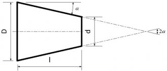
Morse taper is one of the most common means for securing a tool on a machine. This instrument received its name in honor of the famous engineer Stephen Morse, who lived in the 19th century. Today, fractional numbers are used to correctly select the size of this product. There are several standardized values, differing in angles of inclination and sizes.
The area of application of the Morse cone is mechanical engineering. With its help you can quickly and very accurately secure the cutting tool. To do this, the Morse taper is mounted in the machine in a special hole or chuck, and a drill, for example, is inserted into it. This fastening method guarantees the most accurate centering and subsequent processing. It can also be used to supply cutting fluid to the workpiece or cutting tool.
Dimensions and elements of the Morse cone
The distinguishing feature of one Morse taper from another is its size. There are several types of them and, in accordance with GOST, each has a specific number and abbreviation. To measure it, you need to use a calibration, or best of all, a special table that will allow you to calculate dimensions down to the micron. Depending on the machine on which the part will be processed, you should choose, for example, a cutter, a drill, and then the type of invention of Stephen Morse.
With the development of the engineering industry, a need arose to expand the model range of Morse cones. For this purpose, a metric cone was developed, which did not have any special design differences from its predecessor. Its taper was 1:20, with an angle of 2°51'51″ and a slope of 1°25'56″. Metric tapers have made it possible to create a large selection of tools for various machines and operations. They are classified into two categories: large and small. Large ones are designated, for example, No. 120, 200, and the numbers correspond to the largest diameter of the metric cone.
Morse taper dimensions
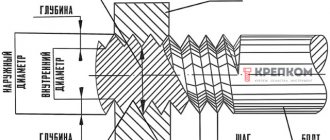
A tool taper is a conical shank of some cutting tool and a conical hole in the spindle or headstock of the same diameter. Its function is to quickly change cutting tools and maintain high precision when centering and clamping.
It is used mainly in CNC machines because it eliminates a number of disadvantages of a conventional Morse taper.
- jamming of shanks in the spindle is much less;
- smaller sizes;
- improved axial stop;
- ease of fastening;
- automatic change of cutting tool.
Nowadays, Morse cones are manufactured in accordance with the international ISO and DIN standards. In Russia, the standardization system combines into one class both simple Morse cones, as well as metric and instrumental ones. Information about them can be obtained from GOST 25557-82. The situation with a single GOST has developed due to the fact that Morse cones have been very popular in our country since the times of the USSR, and in parallel with this, many new ones have appeared.
Morse tapers are divided into 8 categories. Abroad these are MT0, MT1, MT2, MT3, MT4, MT5, MT6, MT7. In Germany, the numbering is the same, but the letter designation is MK. In our country and in the post-Soviet space KM0, KM1, KM2, KM3, KM4, KM5, KM6 and No. 80.
As time has shown, some foreign-made Morse cones are inconvenient to use due to their large length. For this case, a series of shortened products has been developed, having 9 sizes.
Morse taper and metric taper [edit | edit code ]
Morse taper is one of the most widely used tool mounts. It was proposed by Stephen A. Morse around 1864 [1].
The Morse taper is divided into eight sizes, from KM0
to
KM7
(English Morse taper, MT0-MT7, German Morsekegel, MK0-MK7) [2] [3]. Taper from 1:19.002 to 1:20.047 (cone angle from 2°51'26″ to 3°00'52″, cone slope from 1°25'43″ to 1°30'26″) depending on the size.
Morse taper standards: ISO 296, DIN 228, GOST 25557-2016 “Tool tapers. Basic dimensions."
.
In the Russian standard KM7
is not recommended for use; instead, the incompatible metric cone No. 80 is used. Cones made according to inch and metric standards are interchangeable in everything except the shank thread.
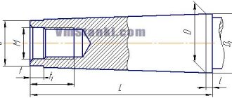
There are several designs of the cone shank: with a claw, with threads and without them. The tool with the foot is secured in the spindle by wedging this foot, for which purpose there is a corresponding groove in the sleeve of some spindles. The foot is designed to make it easier to knock the cone out of the spindle and prevent rotation. A tool with an internal thread is fixed in the spindles by a rod (pivot) that is screwed into the end of the cone. Threaded cones ensure that the tool does not fall out and make it easier to remove a jammed cone from the spindle. The spindle is usually made for one of the fixation options - with a foot, with a pin, or with friction fixation. Since the cone angle is less than the friction angle, fixation of the shank in the socket can also occur only due to friction forces, without the use of pins and claws.
Some cones are equipped with a system of holes and grooves for supplying cutting fluid (coolant).
Metric cone [ edit | edit code ]
As the machine tool industry developed, it became necessary to expand the range of sizes of Morse cones, both larger and smaller. At the same time, for the new standard sizes of the cone, they chose a taper of exactly 1:20 (cone angle 2°51'51″, cone slope 1°25'56″) and called them metric cones
(English Metric Taper). The standard size of metric cones is indicated by the largest diameter of the cone in millimeters. GOST 25557-2016 also defines reduced metric cones No. 4 and No. 6 (eng. ME4, ME6) and large metric cones No. 80, 100, 120, 160, 200 (eng. ME80 - ME200).
There are no design differences between the Morse taper and the metric taper.
Dimensions of the outer and inner cone (according to GOST 25557-2006), mm
- ↑ Not included in GOST 25557-2006
Basic information about shanks and their designation
There are several types of instrument cones. It may contain threads, a foot or do without them.
A thread can be cut at its end, which is made to secure the tool to the spindle using a pin. This is a special rod that prevents the tool from falling out. It can also be used to remove the product if it accidentally gets stuck in the spindle.
If the shank is made with a foot, then it holds the tool in the spindle due to the fact that it is secured in a special groove. The foot has two purposes: with its help it is easier to remove the product from the spindle, and it also creates a rigid fixation and there will be no turning.
You can also find a design with several grooves and holes. They have different depths and sizes. Their task is to supply cutting fluid to the cutting tool.
Tool shanks come in different designs and are designated by letter codes. Below is their transcript:
- BI – internal, there is a groove;
- BE – external, there is a foot;
- AI – internal, there is a hole along the axis;
- AE – external, there is a hole along the axis with a thread;
- BIK – internal, there is a groove and a hole for supplying cutting fluid (coolant);
- VEK – external, there is a foot and a hole for coolant supply;
- AIK – internal, contains holes along the axis and for coolant supply;
- AEK – external, contains an axial hole with a thread and a hole for coolant supply.
1 area of use
1 area of use
1.1 This standard applies to tool shanks with a 7:24 taper for manual and automatic tool changing.
1.2 Shanks for manual tool changing should be made with tapers from 30 to 80.
1.3 Tool shanks for automatic tool changing should be made with cones from 30 to 60, three types: A, U, and J of the following designs: - AD, UD, and JD - with a central hole for supplying cutting fluid (coolant); — AF, UF and JF — with side holes for supplying cutting fluid (coolant).
2 Normative references
This standard uses regulatory references to the following interstate standards: GOST ISO 7388-3-2014* Threaded inserts for fastening tool shanks with a 7:24 cone of types AC, AD, AF, UC, UD, UF, JD and JF. Dimensions ________________ *Probably an error in the original. Should read: GOST ISO 7388-3-2014. — Note from the database manufacturer. GOST 14034-74 Center holes. Dimensions GOST 19860-93 Internal and external cones with a taper of 7:24. Tolerances GOST 30064-93 Ends of spindles of drilling, boring and milling machines. Dimensions. Technical requirements GOST 30893.1-2002 (ISO 2768-1-89) Basic standards of interchangeability. General tolerances. Maximum deviations of linear and angular dimensions with unspecified tolerances GOST 30893.2-2002 (ISO 2768-2-89) Basic standards of interchangeability. General tolerances. Tolerances of the shape and location of surfaces not specified individually Note - When using this standard, it is advisable to check the validity of the reference standards in the public information system - on the official website of the Federal Agency for Technical Regulation and Metrology on the Internet or using the annual information index "National Standards", which published as of January 1 of the current year, and according to issues of the monthly information index “National Standards” for the current year. If the reference standard is replaced (changed), then when using this standard you should be guided by the replacing (changed) standard. If the reference standard is canceled without replacement, then the provision in which a reference is made to it is applied in the part that does not affect this reference.
3 Dimensions
3.1 Main dimensions of shanks for manual tool changing
3.1.1 The dimensions of the conical part of the shank must correspond to those indicated in Figure 1 and Table 1.
Figure 1 - Dimensions of the conical part of the shank
________________ 1) It is allowed to manufacture shanks without a groove for the exit of the grinding wheel between the base diameter and the flange. In this case, the diameter of the cylindrical transition surface D
=
D
. 2) Maximum deviation of the position of the main plane.
1
- main plane;
2
- groove for the exit of the grinding wheel Figure 1
Table 1
| Dimensions in millimeters | |||||||
| Shank taper designation | Tapered part of the shank | Cylindrical part | |||||
| D | z | L h12 | d a10 | p | d | ||
| 30 | 31,75 | 0,4 | 68,4 | 48,4 | 17,4 | 3 | 16,5 |
| 40 | 44,45 | 93,4 | 65,4 | 25,3 | 5 | 24,0 | |
| 45 | 57,15 | 106,8 | 82,8 | 32,4 | 6 | 30,0 | |
| 50 | 69,85 | 126,8 | 101,8 | 39,6 | 8 | 38,0 | |
| 55 | 88,90 | 164,8 | 126,8 | 50,4 | 9 | 48,0 | |
| 60 | 107,95 | 206,8 | 161,8 | 60,2 | 10 | 58,0 | |
| 65 | 133,35 | 246,0 | 202,0 | 75,0 | 12 | 72,0 | |
| 70 | 165,10 | 296,0 | 252,0 | 92,0 | 14 | 90,0 | |
| 75 | 203,20 | 370,0 | 307,0 | 114,0 | 16 | 110,0 | |
| 80 | 254,00 | 469,0 | 394,0 | 140,0 | 18 | 136,0 | |
| 1)D 1 - diameter in the main plane. | |||||||
End of table 1
| Dimensions in millimeters | |||||||||||
| Shank taper designation | Groove | Threaded hole | |||||||||
| y | b H12 | A , no more | t | d | d , no more | g | , no less | , no less | -0,5 | ||
| 30 | 1,6 | 16,1 | 16,2 | 0,12 | 13 | 16,0 | M12 | 24 | 34 | 62,9 | 5,5 |
| 40 | 22,5 | 17 | 21,5 | M 16 | 32 | 43 | 85,2 | 8,2 | |||
| 45 | 3,2 | 19,3 | 29,0 | 21 | 26,0 | M 20 | 40 | 53 | 96,8 | 10,0 | |
| 50 | 25,7 | 35,3 | 0,2 | 26 | 32,0 | M 24 | 47 | 62 | 115,3 | 11,5 | |
| 55 | 45,0 | 36,0 | 153,3 | ||||||||
| 60 | 60,0 | 32 | 44,0 | M30 | 59 | 76 | 192,8 | 14,0 | |||
| 65 | 4,0 | 32,4 | 72,0 | 0,3 | 38 | 52,0 | M36 | 70 | 89 | 230,0 | 16,0 |
| 70 | 86,0 | 280,0 | |||||||||
| 75 | 5,0 | 40,5 | 104,0 | 50 | 68,0 | M40 | 92 | 115 | 350,0 | 20,0 | |
| 80 | 6,0 | 132,0 | 449,0 | ||||||||
3.1.2 The dimensions of the shank flange must correspond to those indicated in Figure 2 and Table 2.
Figure 2 - Shank flange dimensions
1
- main plane;
2
- tool attachment area Figure 2
table 2
| Dimensions in millimeters | |||||
| Shank taper designation | D | i ±0,1 | D * | D , no more | j , no less |
| 30 | 31,75 | 9,6 | 50,0 | 36 | 9 |
| 40 | 44,45 | 11,6 | 63,0 | 50 | 11 |
| 45 | 57,15 | 15,2 | 80,0 | 68 | 13 |
| 50 | 69,85 | 97,5 | 78 | 16 | |
| 55 | 88,90 | 17,2 | 130,0 | 110 | |
| 60 | 107,95 | 19,2 | 156,0 | 136 | |
| 65 | 133,35 | 22,0 | 195,0 | ** | |
| 70 | 165,10 | 24,0 | 230,0 | ||
| 75 | 203,20 | 27,0 | 280,0 | ||
| 80 | 254,00 | 34,0 | 350,0 | ||
| * By agreement with the customer, an increase in size is allowed D to values equal to the diameter of the outer surface of the spindle end according to GOST 30064. ** Dimensions - as agreed with the customer. | |||||
3.2 Main dimensions of shanks for automatic tool changing
3.2.1 The dimensions of type A and U shanks must correspond to those indicated in Figure 3 and Table 3.
Figure 3 - Shank dimensions A and U
________________ 1) Radius or chamfer - at the discretion of the manufacturer. 2) At the discretion of the manufacturer. 3) Depth 0.4 mm.
1
- main plane;
2
- reference base for determining the position of the cutting edge of the tool;
3
- transition between cone and flange;
4
- measuring roller;
5
- tool attachment area Figure 3
Table 3
| Dimensions in millimeters | |||||||||||||
| Shank taper designation | 30 | 40 | 45 | 50 | 60 | ||||||||
| A | U | A | U | A | U | A | U | A | U | ||||
| b +0,2 | 16,1 | 19,3 | 25,7 | ||||||||||
| d | 31,75 | 44,45 | 57,15 | 69,85 | 107,95 | ||||||||
| d H7 | 13 | 17 | 21 | 25 | 32 | ||||||||
| d | Nom. | 45 | 31,75 | 50 | 44,45 | 63 | 57,15 | 80 | 69,95 | 130 | 107,95 | ||
| Prev. off | no more | ±0,15 | no more | ±0,15 | no more | ±0,15 | no more | ±0,15 | no more | ±0,15 | |||
| d -0,5 | 44,3 | 39,15 | 56,25 | 75,25 | 91,25 | 147,7 | 132,8 | ||||||
| d -0,1 | 50 | 46,05 | 63,55 | 82,55 | 97,5 | 98,5 | 155 | 139,75 | |||||
| d ±0,05 | 59,3 | 54,85 | 72,3 | 91,35 | 107,25 | 108,25 | 164,25 | 149,5 | |||||
| d 6H | M12 | M16 | M20 | M24 | M30 | ||||||||
| d no more | 14,5 | 19 | 23,5 | 28 | 36 | ||||||||
| d | — | 9,52 | — | 9,52 | — | 9,52 | — | 9,52 | — | 9,52 | |||
| e no less | 35 | 38 | |||||||||||
| 15,9 | |||||||||||||
| j -0,3 | 15 | — | 18,5 | — | 24 | — | 30 | — | 49 | — | |||
| -0,3 | 47,8 | 68,4 | 82,7 | 101,75 | 161,9 | ||||||||
| no less | 24 | 32 | 40 | 47 | 59 | ||||||||
| no less | 33,5 | 42,5 | 52,5 | 61,5 | 76 | ||||||||
| +0,5 | 5,5 | 8,2 | 10 | 11,5 | 14 | ||||||||
| Nom. | 16,3 | 22,7 | 29,1 | 35,5 | 54,5 | ||||||||
| Prev. off | -0,3 | -0,4 | |||||||||||
| Nom. | 18,8 | 25 | 31,3 | 37,7 | 59,3 | 56,8 | |||||||
| Prev. off | -0,3 | -0,4 | |||||||||||
| -0,5 | 1,6 | 2 | |||||||||||
| Nom. | 0,6 | 1,2 | 2 | 2,5 | 3,5 | ||||||||
| Prev. off | -0,3 | -0,5 | |||||||||||
| -0,5 | 0,8 | 1 | 1,2 | 1,5 | 2 | ||||||||
| -0,5 | 1,6 | 2 | |||||||||||
| t | 0,001 | 0,002 | 0,003 | ||||||||||
| t | 0,002 | 0,003 | 0,004 | ||||||||||
| t | 0,12 | 0,2 | |||||||||||
| u -0,1 | 19,1 | ||||||||||||
| v ±0,1 | 11,1 | ||||||||||||
| x +0,15 | 3,75 | ||||||||||||
| y ±0,1 | 3,2 | ||||||||||||
| 8°17‘ 50 | |||||||||||||
| d measured in the main plane. | |||||||||||||
3.2.2 For shanks of versions AD and UD, the diameter of the central hole for coolant supply is d
indicated in Figure 4. Diameter
d
must be less than or equal to the thread diameter of the shank hole and the thread diameter of the threaded insert according to GOST ISO 7388-3.
Figure 4 - Diameter of the central hole for coolant supply - a(10) for shanks of versions AD and UD
Figure 4
3.2.3 For shanks of AF and UF versions, the dimensions of the side holes for coolant supply are indicated in Figure 5 and Table 4. The side holes for coolant supply must withstand operating pressure up to 5 MPa; design is at the discretion of the manufacturer.
Figure 5 - Dimensions of side holes for coolant supply for AF and U shanks
Figure 5
Table 4
| Dimensions in millimeters | ||
| Shank taper designation | d no more | e |
| 30 | 4 | 21 |
| 40 | 27 | |
| 45 | 5 | 35 |
| 50 | 6 | 42 |
| 60 | 8 | 66 |
3.2.4 Shanks of types A, U, versions AD, UD, AF and UF can be manufactured with a slot for storage media, the dimensions of which must correspond to those indicated in Figure 6 and Table 5.
Figure 6—Size of media slot for type A and U shanks
________________ The storage media socket is located on the axis of the tool’s cutting edge.
Figure 6
Table 5
| In millimeters | |
| With , no more | 0,3×45° |
| d 13 +0,09 | 10 |
| l8 +0.2 | 4,6 |
| Notes 1 At the discretion of the manufacturer, chamfer With 45° can be replaced by a radius | |
3.2.5 The dimensions of type J shanks must correspond to those shown in Figure 7 and Table 6.
Figure 7 — Dimensions of type J shanks
________________ 1) Radius or chamfer - at the discretion of the manufacturer. 2) At the discretion of the manufacturer.
1
- main plane;
2
— plane of location of the top of the cutting edge of the tool;
3
- transition between cone and flange;
4
- measuring roller;
5
- tool attachment area Figure 7
Table 6
| Dimensions in millimeters | ||||||
| Shank taper designation | 30 | 40 | 45 | 50 | 60 | |
| b +0,2 | 16,1 | 19,3 | 25,7 | |||
| d | 31,75 | 44,45 | 57,15 | 69,85 | 107,95 | |
| d H8 | 12,5 | 17 | 21 | 25 | 31 | |
| d -0,5 | 38 | 53 | 73 | 85 | 135 | |
| d h8 | 46 | 63 | 85 | 100 | 155 | |
| d ±0,05 | 56,03 | 75,56 | 100,09 | 118,89 | 180,22 | |
| d 6H | M12 | M16 | M20 | M24 | M30 | |
| d | 8 | 10 | 12 | 15 | 20 | |
| d no more | 14,5 | 19 | 23,5 | 28 | 36 | |
| 20 | 25 | 30 | 35 | 45 | ||
| ±0,2 | 48,4 | 65,4 | 82,8 | 101,8 | 161,8 | |
| no less | 24 | 30 | 36 | 45 | 56 | |
| no less | 34 | 43 | 50 | 62 | 76 | |
| +0,5 | 7 | 9 | 11 | 13 | 16 | |
| no less | 17 | 21 | 26 | 31 | 34 | |
| Nom. | 16,3 | 22,6 | 29,1 | 35,4 | 60,1 | |
| Prev. off | -0,3 | -0,4 | ||||
| -0,5 | 1,6 | 2 | ||||
| 0,5 | 1 | |||||
| -0,5 | 0,8 | 1 | 1,2 | 1,5 | 2 | |
| t | 0,001 | 0,002 | 0,003 | |||
| t | 0,002 | 0,003 | 0,004 | |||
| t | 0,12 | 0,2 | ||||
| u | 22 | 27 | 33 | 38 | 48 | |
| N ±0,1 | 13,6 | 16,6 | 21,2 | 23,2 | 28,2 | |
| X | 4 | 5 | 6 | 7 | 11 | |
| y ±0,4 | 2 | 3 | ||||
| 8°17‘ 50 | ||||||
| d measured in the main plane. | ||||||
3.2.6 For JD shanks, the diameter of the central hole for coolant supply is d
indicated in Figure 8. Diameter
d
10 must be less than or equal to the thread diameter of the shank hole and the thread diameter of the threaded insert according to GOST ISO 7388-3.
Figure 8 - Diameter of the central hole for coolant supply - a(10) for JD shanks
Figure 8
3.2.7 For JF-design shanks, the dimensions of the side holes for coolant supply are indicated in Figure 9 and Table 7. The side holes for coolant supply must withstand operating pressure up to 5 MPa; design is at the discretion of the manufacturer.
Figure 9 — Dimensions of side holes for coolant supply for JF shanks
Figure 9
Table 7
| Dimensions in millimeters | ||
| Shank taper designation | d no more | e |
| 30 | 2 | 20 |
| 40 | 4 | 27 |
| 45 | 5 | 35 |
| 50 | 6 | 42 |
| 60 | 8 | 66 |
3.2.8 Shanks of type J, versions JD and JF can be manufactured with a socket for a storage medium, the dimensions of which must correspond to those indicated in Figure 10 and Table 8.
Figure 10 — J Type Shank Media Slot Dimensions
________________ 1) The socket for the storage medium is located on the axis of the cutting edge of the tool.
Figure 10
Table 8
| Dimensions in millimeters | |||||
| Shank taper designation | 30 | 40 | 45 | 50 | 60 |
| With no more | 0,3×45° | ||||
| d +0,09 | 10 | ||||
| +0,2 | 4,6 | ||||
| 11 | 14,5 | 18 | 20,5 | ||
| Notes 1 At the discretion of the manufacturer, chamfer With 45° can be replaced by a radius | |||||
4 Characteristics
4.1 Dimensions and shape of the center hole - in accordance with GOST 14034: - shape H - for shanks for manually changing tools; — shape F — for shanks for automatic tool changing.
4.2 Shanks of tools with a 7:24 taper must be heat treated taking into account the required strength, hardness, and depth of the hardened layer. In this case, the requirements for rigidity and wear must be met.
4.3 Unspecified maximum deviations - according to tolerance class m in accordance with GOST 30893.1 and class K in accordance with GOST 30893.2.
4.4 The degree of accuracy of cones AT4, AT5, tolerances of the angle and shape of the cone - according to GOST 19860. The deviation of the cone angle from the nominal should be placed in the “plus”.
5 Designation
5.1 The designation of tool shanks with a 7:24 taper for manual tool changing in accordance with this standard shall include:
a) the word “Shank”;
b) designation of the shank cone;
c) GOST designation. An example of a symbol for a shank with a 7:24 taper for manual tool changing with a 40 taper:
Shank 40
GOST 25827-2014
5.2 The designation of tool shanks with a 7:24 taper for automatic tool changing in accordance with this standard shall include:
a) the word “Shank”;
b) designation of the type or design of the shank A, AD, AF, U, UD, UF, J, JD or JF;
c) designation of the shank cone;
d) “D” for a design with a slot for storage media;
e) GOST designation An example of a symbol for a shank with a 7:24 taper for automatic tool changing of type A with a 40 taper:
Shank A 40
GOST 25827-2014
Same for U-shape shank with media slot:
Shank U 40 - D
GOST 25827-2014
Shortened Morse tapers
In some situations, the dimensions of the Morse cone are too large and in this case you should use shortened versions.
The names below indicate that the cone has been shortened:
- B7 - up to 14 mm;
- B10 - up to 18 mm;
- B12 - up to 22 mm;
- B16 - up to 24 mm;
- B18 - up to 32 mm;
- B22 - up to 45 mm;
- B24 - up to 55 mm;
- B32 - up to 57 mm;
- B45 - up to 71 mm;
The number in the name informs about the size of the diameter of the new part of the cone. Detailed data can be taken from the relevant GOST.
If you find an error, please select a piece of text and press Ctrl+Enter.
| definitions and maximum deviations |
NORMAL ANGLES (GOST 8908-81)
The table does not apply to the angular dimensions of cones. When choosing corners, the 1st row should be preferred to the 2nd, and the 2nd to the 3rd.
NORMAL TONES and ANGLES OF CONES (GOST 8593-81)
The standard applies to the tapers and taper angles of smooth conical elements of parts.
Note. The taper or cone angle values indicated in the “Cone designation” column are taken as the initial values when calculating other values given in the table. When selecting tapers or taper angles, Row 1 should be preferred to Row 2.
TOOL CONES SHORTENED (GOST 9953-82)
The standard applies to short tool Morse tapers.
*z – the largest permissible deviation of the position of the main plane in which diameter D is located from the theoretical position. **dimensions for reference.
| Cone designation | Morse cone | D | D1 | d | d1 | l1 | l2 | a, no more | b | c | ||||
| B7 | 7,067 | 7,2 | 6,5 | 6,8 | 11,0 | 14,0 | 3,0 | 3,0 | 0,5 | |||||
| B10 B12 | 1 | 10,094 12,065 | 10,3 12,2 | 9,4 11,1 | 9,8 11,5 | 14,5 18,5 | 18,0 22,0 | 3,5 3,5 | 3,5 3,5 | 1,0 1,0 | ||||
| B16 B18 | 2 | 15,733 17,780 | 16,8 18,0 | 14,5 16,2 | 15,0 16,8 | 24,0 32,0 | 29,0 37,0 | 5,0 5,0 | 4,0 4,0 | 1,5 1,5 | ||||
| B22 B24 | 3 | 21,793 23,825 | 22,0 24,1 | 19,8 21,3 | 20,5 22,0 | 40,5 50,5 | 45,5 55,5 | 5,0 5,0 | 4,5 4,5 | 2,0 2,0 | ||||
| B32 | 4 | 31,267 | 31,6 | 28,6 | – | 51,0 | 57,5 | 6,5 | – | 2,0 | ||||
| B45 | 5 | 44,399 | 44,7 | 41,0 | – | 64,5 | 71,0 | 6,5 | – | 2,0 | ||||
| Dimensions D1 and d are theoretical, resulting respectively from diameter D and nominal dimensions a and l1 | ||||||||||||||
TAPER OF OUTER AND INTERNAL CONES AND THREADED HOLE CONES
| Designation of cone size | Taper | Cone angle 2α |
| B7 B10, B12 B16, B18 B22, B24 B32 B45 | 1 : 19,212 = 0,05205 1 : 20,047 = 0,49880 1 : 20,020 = 0,04995 1 : 19,922 = 0,05020 1 : 19,954 = 0,05194 1 : 19,002 = 0,05263 | 2°58′54″ 2°51′26″ 2°51′41″ 2°52′32″ 2°58′31″ 3°00′53″ |
| 2α cone angle is calculated from the taper value, rounded to the nearest 1″. | ||
RECOMMENDED CENTER HOLE DIMENSIONS FOR SHORT CONE
INSTRUMENTAL MORSE AND METRIC EXTERNAL CONES (GOST 25557-2006)
| Cone type | Metric | Morse | Metric | |||||||||||
| Designation | 4 | 6 | 1 | 2 | 3 | 4 | 5 | 6 | 80 | 100 | 120 | 160 | 200 | |
| D | 4,0 | 6,0 | 9,045 | 9,065 | 17,78 | 23,825 | 31,267 | 44,399 | 63,348 | 80 | 100 | 120 | 160 | 200 |
| D1 | 4,1 | 6,2 | 9,2 | 12,2 | 18,0 | 24,1 | 31,6 | 44,7 | 63,8 | 80,4 | 100,5 | 120,6 | 160,8 | 201,0 |
| d* | 2,9 | 4,4 | 6,4 | 9,4 | 14,6 | 19,8 | 25,9 | 37,6 | 53,9 | 70,2 | 88,4 | 106,6 | 143 | 179,4 |
| d1 | – | – | – | M6 | M10 | M12 | M16 | M20 | M24 | M30 | M36 | M36 | M48 | M48 |
| d4 max | 2,5 | 4,0 | 6,0 | 9,0 | 14,0 | 19,0 | 25,0 | 35,7 | 51,0 | 67,0 | 85,0 | 102,0 | 138,0 | 174,0 |
| lmin _ | – | – | – | 16,0 | 24,0 | 24,0 | 32,0 | 40,0 | 47,0 | 59,0 | 70,0 | 70,0 | 92,0 | 92,0 |
| l1 | 23,0 | 32,0 | 50,0 | 53,5 | 64,0 | 81,0 | 102,5 | 129,5 | 182,0 | 196,0 | 232,0 | 268,0 | 340,0 | 412,0 |
| l2 | 25,0 | 35,0 | 53,0 | 57,0 | 69,0 | 86,0 | 109,0 | 136,0 | 190,0 | 204,0 | 242,0 | 280,0 | 356,0 | 432,0 |
| l11 | – | – | – | 4,0 | 5,0 | 5,5 | 8,2 | 10,0 | 11,5 | – | – | – | – | – |
| * – size for reference. – the angle of Morse cones No. 0-No. 5 corresponds to the angle of shortened Morse cones; No. 6 – 1:19.180 = 0.05214 – angle of metric cones – 1:20 = 0.05. | ||||||||||||||
Cone 7:24 [edit | edit code ]
A widely used tool taper, mainly for CNC machines with automatic tool change. The goal of the development is to eliminate the disadvantages of the Morse taper (self-jamming of the cone in the spindle, small area of the axial stop, large length, difficulty in automatically fixing the cone in the spindle, lack of hooks for automatic tool changing).
There are a number of national and international standards for this cone, differing in the basic dimension (inch or metric), auxiliary elements (flanges, pins, coolant channels) and designations. Cones made to different standards are not always interchangeable.
- ISO
cones. International standards ISO 297:1988 (design version for manual tool change), ISO 7388 (design version for automated tool change). - New Russian standards: GOST
25827-2014 - designs of cones, flanges and shank threads. GOST ISO 7388-3-2014, which is paired with it, is the design of the posts. Almost a duplicate of ISO 297 and ISO 7388. - Soviet and old Russian standards may still be relevant:
- GOST 15945-82 - main dimensions of cones and the paired GOST 19860-93 - tolerances.
- GOST 25827-93 - designs of cones, flanges and shanks.
| Cone designation | Taper | D | D1 | d | d1 | d2 | d3 max | d4 max | d5 | l1 max | l2 max | l3 max | l4 max | l5 min | l6 | |
| Metric | № 4 | 1:20 | 4 | 4,1 | 2,9 | – | – | – | 2,5 | 3 | 23 | 25 | – | – | 25 | 21 |
| № 6 | 1:20 | 6 | 6,2 | 4,4 | – | – | – | 4 | 4,6 | 32 | 35 | – | – | 34 | 29 | |
| Morse | KM0 | 1:19,212 | 9,045 | 9,2 | 6,4 | – | 6,1 | 6 | 6 | 6,7 | 50 | 53 | 56,3 | 59,5 | 52 | 49 |
| KM1 | 1:20,047 | 12,065 | 12,2 | 9,4 | M6 | 9 | 8,7 | 9 | 9,7 | 53,5 | 57 | 62 | 65,5 | 56 | 52 | |
| KM2 | 1:20,020 | 17,780 | 18 | 14,6 | M10 | 14 | 13,5 | 14 | 14,9 | 64 | 69 | 75 | 80 | 67 | 62 | |
| KM3 | 1:19,992 | 23,825 | 24,1 | 19,8 | M12 | 19,1 | 18,5 | 19 | 20,2 | 80,1 | 86 | 94 | 99 | 84 | 78 | |
| KM4 | 1:19,254 | 31,267 | 31,6 | 25,9 | M16 | 25,2 | 25,2 | 24 | 26,5 | 102,5 | 109 | 117,5 | 124 | 107 | 98 | |
| KM5 | 1:19,002 | 44,399 | 44,7 | 37,6 | M20 | 36,5 | 35,7 | 35,7 | 38,2 | 129,5 | 136 | 149,5 | 156 | 135 | 125 | |
| KM6 | 1:19,180 | 63,348 | 63,8 | 53,9 | M24 | 52,4 | 51 | 51 | 54,6 | 182 | 190 | 210 | 218 | 188 | 177 | |
| KM7 [sn 1] | 1:19,231 | 83,058 | – | 285.75 | 294.1 | |||||||||||
| Metric | № 80 | 1:20 | 80 | 80,4 | 70,2 | M30 | 69 | 67 | 67 | 71,5 | 196 | 204 | 220 | 228 | 202 | 186 |
| № 100 | 1:20 | 100 | 100,5 | 88,4 | M36 | 87 | 85 | 85 | 90 | 232 | 242 | 260 | 270 | 240 | 220 | |
| № 120 | 1:20 | 120 | 120,6 | 106,6 | M36 | 105 | 102 | 102 | 108,5 | 268 | 280 | 300 | 312 | 276 | 254 | |
| № 160 | 1:20 | 160 | 160,8 | 143 | M48 | 141 | 138 | 138 | 145,5 | 340 | 356 | 380 | 396 | 350 | 321 | |
| № 200 | 1:20 | 200 | 201 | 179,4 | M48 | 177 | 174 | 174 | 182,5 | 412 | 432 | 460 | 480 | 424 | 388 |
- DV
,
SK
(from German Steilkegel). German version of the cone. Standards DIN 2080, DIN 69871. - NMTB
(from the English National Machine Tool Builders Association),
NST
,
NT
. American version of the cone. ANSI B5.18 standard. Inch dimension, structurally similar to ISO 297. - CAT
,
CV
(from English Caterpillar V-Flange). American version of the cone. ANSI B5.50 standard. Inch dimension, structurally similar to ISO 7388 option A. - BT
is a Japanese type of cone according to JIS B6339 (JMTBA MAS-403 “BT”). Inch dimension, structurally similar to ISO 7388 option J. - NFE 62540
is a French standard. - IS 2340
,
IS 11173
- Indian standards. The first is analogous to ISO 297, the second is ISO 7388.
The standard size of the cone is indicated by a number; there are sizes from 10 to 80 in increments of 5. For example, ISO10, NMTB40, BT50. For all standards, the size of the conical part is the same. Cone angle 16°35'40″. Cone size table D
denotes the basic size - the largest diameter of the conical hole (socket),
L
denotes the depth of the conical hole.
These values also approximately correspond to the largest diameter of the cone and its length. DF
flange is approximately the same for all design varieties.
| Cone | D | L | Thread | DF |
| 10 | 15,87 | 21,8 | ||
| 15 | 19,05 | 26,9 | ||
| 25 | 25,40 | 39,8 | ||
| 30 | 31,75 | 49,2 | M12 | 50 |
| 35 | 38,10 | 57,2 | ||
| 40 | 44,45 | 65,6 | M16 | 63 |
| 45 | 57,15 | 84,8 | M20 | 80 |
| 50 | 69,85 | 103,7 | M24 | 97 |
| 55 | 88,90 | 132,0 | M24 | 130 |
| 60 | 107,95 | 163,7 | M30 | 156 |
| 65 | 133,35 | 200,0 | M36 | 195 |
| 70 | 165,10 | 247,5 | M36 | 230 |
| 75 | 203,20 | 305,8 | M40 | 280 |
| 80 | 254,00 | 390,8 | M40 | 350 |
ISO standards and the new Russian GOST define several design varieties: one for manual tool changing and three varieties for automatic tool changing, designated by the letters A
,
U
,
J
.
Each design type has its own flange and post. In addition, the standards regulate two methods of supplying coolant to the tool: central through a post (indicated by the letter D
) or lateral through a flange (letter
F
).
The old GOST 25827-93 defined three designs of cones. Execution 1 was similar to ISO 297. Execution 2 was similar to ISO 7388 option A. Execution 3 had no analogues. The standard did not define the designs of the stems, only the flanges and threads of the shanks.
Currently, cones are usually made with interchangeable pins, which improves the compatibility of equipment of different standards.