When purchasing wooden I-beams to order, the calculation is determined by several important points. First of all, the beam must cover the span with a small margin, so that later it can be embedded in the wall. When the wall is brick or concrete, make a recess of 10-15 centimeters. A recess of 7 centimeters is sufficient in a wooden wall.
Variations are possible. For example, you want to use I-beams to create a roof slope. This means that they will have to be taken out about half a meter. When using additional elements, the length of the beam should be the same as the distance from one wall to another. The most optimal calculation option is when the beam covers a distance of 2.5 - 4 meters. With a longer length, its strength may not be enough. In long spans, laminated veneer lumber is used, and columns are installed to serve as supports.
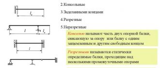
Types of floor beams - advantages and disadvantages
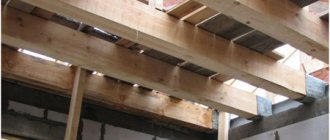
Wooden beams
They are most often chosen as floors in houses made of wood, timber, brick houses and houses built from gas silicate blocks for attic floors, as well as in cases where they want to save on materials, or if the strength of the foundation is not designed for heavy floors between floors , as well as in case of unstable soils on the site.
The main material used for beams of this variation is deciduous and coniferous wood, carefully dried and subjected to special processing, which improves its operational and technical parameters. Such a beam floor includes the beams themselves, insulation, shingles and flooring.
Advantages:
- convenience and ease of installation;
- reasonable cost;
- low weight of the product.
Flaws:
- high level of flammability;
- susceptibility to damage by bark beetles;
- possible rotting of the structure over time;
- The floor structure on wooden beams is used only up to the fourth floor.
In order to simplify the calculation of a wooden beam and the selection of sections and spacing for it, we provide a table that will help determine the preliminary selection of sections for single-span wooden beams. All you have to do is collect the regulatory loads:
During installation, wooden floor beams are laid on transverse supports, which can be an additional beam or an armored belt cast around the perimeter of the masonry wall. Transverse supports serve to evenly distribute the load on the walls, and then on the foundation of the house. Parts of the beams laid on the walls are wrapped in waterproofing material. Typically, roofing felt is used, but the ends are not insulated, which allows the beam to “breathe.”
The most important thing when choosing a material for flooring over wooden beams is to carefully select high-quality wood without cracks, damage, well-dried, impregnated against fire and rot, as well as with a design section of the beams suitable for construction.
In private construction, a common practice is the use of monolithic concrete floors, or other types of the most durable floors on the lower floors of the building, and the simultaneous use of beam floors on higher floors - for example, the attic. This is done in order to lighten the overall loads on the foundation.
Steel beams
Metal floor beams are made of high-strength steel alloy using hot or cold rolling technology. Structurally, they are presented in the form of an I-beam, channel or angle, with I-beams having the greatest demand and popularity. Laying is possible both “flat” and on the edge.
Advantages:
- spans of greater length are permissible than when using wooden beams;
- resistance to biological influences and decay;
- fire resistance.
Flaws:
- high price;
- corrosion is possible;
- low sound and heat insulation parameters;
- installation requires special equipment.
Reinforced concrete beams
Reinforced concrete floor beams are the best option for large-scale construction, capable of withstanding even significant external loads over a long span. Load parameters are presented at a very high level.
Advantages:
- no deflections;
- increased load-bearing capacity;
- formation of long spans with various shapes.
Flaws:
- complexity of installation;
- the need to use specialized equipment.
Combined beams
The combined beam is made on the basis of several materials at once, for example, wood and OSB. Their use is widespread in private construction when creating frame houses. Products can have different shapes, but the most common is the combined I-beam, which can effectively resist various kinds of external loads, withstanding even significant stresses.
Advantages:
- excellent strength data;
- resistance to deformation;
- light weight.
Flaws:
- high price;
- inconvenience of insulation with slab material.
Initial data
Span length (L) is the distance between the two inner edges of the walls. In other words, the span that the calculated beams cover.
Beam pitch (P) is the step along the center of the beams through which they are laid.
Type of ceiling - if you will not live on the top floor, and it will not be heavily cluttered with things dear to your heart, then select “Attic”, in other cases - “Interfloor”.
Wall length (X) - the length of the wall on which the beams rest.
Beam length (A) is the largest dimension of the beam.
Weight 1 lm . — this parameter is used as if in the second stage (after you have already selected the desired beam).
Design resistance Ry - this parameter depends on the steel grade. For example, if the steel grade is:
- C235 - Ry = 230 MPa;
- C255 - Ry = 250 MPa;
- C345 - Ry = 335 MPa;
But usually Ry = 210 MPa is used in the calculation in order to protect oneself from various kinds of “force majeure” situations. After all, we live in Russia - they will bring rolled metal from the wrong grade of steel and that’s it.
Elastic modulus E - this parameter depends on the type of metal. For the most common ones, its value is:
- steel - E = 200,000 MPa;
- aluminum - E = 70,000 MPa.
The values of standard and design loads are indicated after they are collected on the floor.
Price per 1 ton - the cost of 1 ton of rolled metal.
Result
Strength calculation:
Wreq is the required moment of resistance of the profile. It is located according to the assortment (there are GOSTs for profiles). The direction (x-x, yy) is selected depending on how the beam will lie. For example, for a channel and an I-beam, if you want to place them (i.e. the larger size is directed upward - [ and Ι ), you need to select “xx”.
Deflection calculation:
Jreq is the minimum permissible moment of inertia. Selected according to the same assortments and according to the same principles as Wreb.
The number of beams is the total number of beams that is obtained when laying them along the wall X with a step P.
Total mass - the weight of all beams of length A.
Cost - the cost of purchasing metal floor beams.
WALL CALCULATION
Strength calculation of walls
The strength calculation of brick walls was carried out in accordance with SP 15.13330.2012 “Stone and reinforced masonry structures” [3].
The calculation of brick pillars (b×h=500×650 mm) along axis B was carried out.
Compliance with the requirement of clause 7.1 of SP 15.13330.2012 [4] was verified:
The value of the calculated compressive resistance of the masonry R is assumed to be 2.0 MPa. The density of the brickwork, as well as the mortar of the plaster layers, is taken on the basis of reference data to be equal to 1900 kg/m3. The reliability factor for the load from the weight of the masonry is taken according to Table 7.1 [1] equal to 1.1.
2) Calculation of brick pillars (b×h=500×650 mm) along axis B. Longitudinal force acting on the lower plane of the pillar
Minimum load-bearing capacity of the pillar section
Conclusion: the load-bearing capacity of brick pillars along axis B is sufficient to absorb the loads acting on them.
4.2. Thermal calculation of walls
1) General provisions Thermal engineering calculations of brick walls were carried out in accordance with SP 50.13330.2012 “Thermal protection of buildings” [6]. A calculation was made of an external brick wall with a thickness of two bricks of pre-revolutionary size
made of solid ceramic brick and plastered on both sides (average layer thickness 25 mm, γ0=1800 kg/m3).
2) Thermal engineering calculation of external walls Wall characteristics
Conclusion: the resistance of the outer wall to heat transfer is insufficient
CALCULATION OF FOUNDATIONS AND BASE SOILS
1) General provisions The calculation of foundations and foundation soils was carried out in accordance with SP 22.13330.2011 “Foundations of buildings and structures” [5]. The calculation of the foundation of a brick pillar along axis B was carried out. Compliance with the requirement of clause 5.6.7 of SP 22.13330.2011 was verified [5]:
where p avg. – average pressure under the base of the foundation; R – design resistance of foundation soils.
In accordance with engineering-geological surveys, silty sandy loams occur in the compressible stratum. The calculated resistance of the foundation soil R is assumed to be 250 kPa. The density of the rubble masonry is taken on the basis of reference data to be 2400 kg/m3.
2) Calculation of the foundation of the longitudinal wall
Conclusion: plastic deformations under the base of the foundation of load-bearing pillars do not develop deeper than the permissible value.
Calculation
To select a metal beam for a particular structure that will bear a certain load, it is necessary to calculate the beam for bending strength.
This can be done by calculating all the parameters yourself using a well-known method or using an online calculator. To select a floor beam, a strength test is made, where the maximum strength of the steel must be greater than the sum of the ratios of the maximum bending moment at the point of action of a particular load to the axial moment, and the shear forces and cross-sectional area at the maximum loaded point.
Selection of the section of a metal beam online
Before starting the calculation of a steel beam, it is necessary to collect the load acting on the metal beam.
Depending on the duration of action, loads are divided into permanent and temporary. Constant loads include:
- own weight of the metal beam;
- own weight of the floor, etc.;
Temporary loads include:
- long-term load (payload, taken depending on the purpose of the building);
- short-term load (snow load, taken depending on the geographical location of the building);
- special load (seismic, explosive, etc. Not taken into account within this calculator);
Loads on a beam are divided into two types: design and standard. Design loads are used to calculate the beam for strength and stability (1st limit state). Standard loads are established by standards and are used to calculate beams for deflection (2nd limit state). Design loads are determined by multiplying the standard load by the reliability load factor. Within the framework of this calculator, the design load is used to determine the deflection of the beam to reserve.
Loads can be collected on our website.
After you have collected the surface load on the floor, measured in kg/m2, you need to calculate how much of this surface load the beam takes on. To do this, you need to multiply the surface load by the pitch of the beams (the so-called load strip).
For example: We calculated that the total load was Qsurface = 500 kg/m2, and the beam spacing was 2.5 m. Then the distributed load on the metal beam will be: Qdistributed = 500 kg/m2 * 2.5 m = 1250 kg/m. This load is entered into the calculator
2. Constructing diagrams
Next, a diagram of moments and transverse forces is constructed. The diagram depends on the loading pattern of the beam and the type of beam support. The diagram is constructed according to the rules of structural mechanics. For the most frequently used loading and support schemes, there are ready-made tables with derived formulas for diagrams and deflections.
3. Calculation of strength and deflection
After constructing the diagrams, a calculation is made for strength (1st limit state) and deflection (2nd limit state). In order to select a beam based on strength, it is necessary to find the required moment of inertia Wtr and select a suitable metal profile from the assortment table. The vertical maximum deflection fult is taken according to table 19 from SNiP 2.01.07-85* (Loads and impacts). Point 2.a depending on the span. For example, the maximum deflection is fult=L/200 with a span of L=6m. means that the calculator will select a section of a rolled profile (I-beam, channel or two channels in a box), the maximum deflection of which will not exceed fult=6m/200=0.03m=30mm. To select a metal profile based on deflection, find the required moment of inertia Itr, which is obtained from the formula for finding the maximum deflection. And also a suitable metal profile is selected from the assortment table.
4. Selection of a metal beam from the assortment table
From two selection results (limit state 1 and 2), a metal profile with a large section number is selected.
Calculation of floor beams
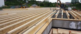
Wood Floor Beams
Wood floor beams are often the most economical option. Wooden beams are easy to manufacture and install, and have low thermal conductivity compared to steel or reinforced concrete beams. The disadvantages of wooden beams are lower mechanical strength, requiring large sections, low fire resistance and resistance to damage by microorganisms and termites (if they are found in your area). Therefore, wooden floor beams must be carefully treated with antiseptics and fire retardants, for example XM-11 or KHMBB produced by Antiseptic (St. Petersburg).
How to calculate the required cross-section of a wooden floor beam?
The optimal span for wooden beams is 2.5-4 meters. The best cross-section for a wooden beam is rectangular with a height to width ratio of 1.4:1. The beams are inserted into the wall at least 12 cm and waterproofed in a circle, except for the end. It is advisable to secure the beam with an anchor embedded in the wall.
When choosing the section of a floor beam, take into account the dead weight load, which for interfloor floor beams is usually 190-220 kg/m2, and the temporary (operational) load, its value is taken equal to 200 kg/m2. Floor beams are laid along a short section of the span. It is recommended to choose the installation step of wooden beams equal to the installation step of the frame racks.
To calculate the minimum and optimal cross-section of a wooden floor beam, you can use Romanov’s online calculator for wooden floor beams
Below are several tables with the values of the minimum sections of wooden beams for various loads and span lengths:
Table of sections of wooden floor beams depending on the span and installation pitch, with a load of 400 kg/m2. - it is recommended to count on this load
If you do not use insulation or do not plan to load the floors (for example, the floor of an uninhabited attic), then you can use the table for lower load values of wooden floor beams:
Table of minimum sections of wooden floor beams depending on the span and load, for loads from 150 to 350 kg/m2.
If you use round logs instead of rectangular beams, you can use the following table:
Minimum permissible diameter of round logs used as interfloor beams depending on the span with a load of 400 kg per 1 m2
If you want to block large runs, we recommend using the experience from the Okolotok website.
Steel (metal) I-beams
An I-beam metal floor beam has a number of undeniable advantages, with only one drawback - high cost. A metal I-beam can cover large spans with significant loads; the metal steel beam is non-flammable and resistant to biological influences. However, a metal beam can corrode in the absence of a protective coating and in the presence of aggressive environments in the room.
To calculate the parameters of an I-beam metal beam, you can use the good calculation program Beam
The weight of one meter of I-beam can be viewed in the I-beam weight table
In most cases in amateur construction, when making calculations in the above program or others similar to it, it should be assumed that the metal beam has hinged supports (that is, the ends are not rigidly fixed - for example, as in a steel frame structure). The load on the floor with steel I-beams, taking into account its own weight, should be calculated as 350 (without screed) -500 (with screed) kg/m2 The step between I-beams is recommended to be 1 meter. In case of savings, it is possible to increase the pitch between metal beams to 1200 mm.
Table for selecting the number of I-beam metal beams at different pitches and lengths of purlins
Reinforced concrete floor beams
When installing reinforced concrete beams, you need to use the following rules (according to Vladimir Romanov):
- The height of the reinforced concrete beam must be at least 1/20 of the length of the opening. Divide the length of the opening by 20 and get the minimum height of the beam. For example, with an opening of 4 m, the height of the beam should be at least 0.2 m.
- The width of the beam is calculated based on the ratio of 5 to 7 (5 is width, 7 is height).
- The beam should be reinforced with at least 4 bars of reinforcement d12-14 (thicker at the bottom) - two at the top and bottom. Tables of the ratio of length and weight of reinforcement of various sections. Concreting at one time, without interruptions, so that the previously laid portion of the mortar does not have time to set before laying a new portion. Concreting beams with a concrete mixer is easier than ordering a mixer. The mixer is good for quickly pouring large volumes.
The weight of construction reinforcement or how many meters of reinforcement in a ton. Weight of reinforcement 11.75 m long. Weight of reinforcement with diameter from 5.5 to 32 mm.
I-beam weight and number of meters per ton of I-beam
Characteristics
Floor beams, depending on the production technology, have different characteristics.
I-beams with inclined shelves. The slope angle is 6-12 degrees. Main parameters:- length – 10-60 cm;
- width – 5.5-19 cm;
- shelf thickness – 7.2 mm-1.8 cm;
- wall thickness – 4.5mm-1.2 cm.
- I-beams with parallel edges (GOST 26020, STO ASChM 20-93) have other characteristics:
- length - B-1 - 100 B-4;
- shelf thickness – 5.7 mm-3.3 cm;
- profile width – 55 mm-32 cm;
- wall thickness – 4.1 mm-1.95 cm.
- Wide-flange metal structures have the following characteristics:
- length - 20Ш1- 70Ш5;
- profile width – 15-32 cm;
- wall thickness – 6.0 mm - 2.3 cm;
- shelf thickness – from 9 mm -3.65 cm.
- Column beams have the following indicators:
- length – 20 K1-40 K5;
- profile width – from 20 to 40 cm;
- wall thickness – from 6.5 to 2.3 cm;
- shelf thickness – 1-3.55 cm.
Interfloor ceiling on metal beams
The task of floors in a building is to perform load-bearing and enclosing functions, to ensure the spatial rigidity of the structure and its stability, to separate floors, to connect walls to each other, transferring the load to them. In low-rise construction there are several options for arranging interfloor floors. One of them is flooring using metal beams. They can also be used for attic and basement floors.
Advantages of metal floors
Metal structures, unlike wooden beams, are more reliable in terms of fire safety and resistance to biological hazards (mold, mildew). They:
- much stronger than wooden beams, with a smaller thickness they can withstand heavy loads. Their use allows you to save space and provide more usable space;
- can be laid on spans up to 24 meters. The I-beam (channel) section of rolled metal remains static, is resistant to changes in the amplitude of the floors, and is not subject to deflection.
How to correctly calculate a metal beam?
Despite the economic crisis raging in the world, which, unfortunately, has also affected our country, the construction of facilities of various importance continues to be carried out. At the same time, industrial construction has recently received a new impetus for development, however, the need of the country's residents for residential square meters has not decreased.
Today, in the construction of industrial and civil facilities, metal floor beams are widely used, which increase the load-bearing capacity of the entire structure.