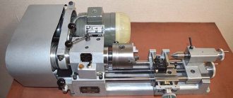
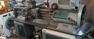
STD-120M Desktop wood lathe for training. Purpose, scope
The STD-120M wood lathe is designed for the manufacture of small-sized wood parts. It compares favorably with its predecessor, the STD-120 machine, primarily in that hazardous areas have a protective fence, the workplace is equipped with local lighting, the electrical control circuit has been improved, measures have been taken to reduce noise and vibration levels, and a specially developed mechanized waste removal system is a dust-collecting system. installation.
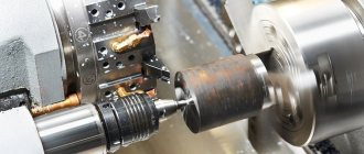
The educational lathe for wood STD-120M is designed for performing light turning work on wood and in centers, on a faceplate or in a chuck, as well as for performing simple drilling work:
- turning of cylindrical and profile bodies of revolution
- facing, rounding and cutting workpieces at various angles
- internal turning according to a given profile and drilling
- profile and decorative processing of flat surfaces of large diameter on a faceplate (such as a plate, cup)
Specifications
Since the device is designed for light turning work, its characteristics are suitable for use in domestic conditions:
- total weight of the unit - 100 kg;
- machine dimensions: 1250 by 575 by 550 mm;
- required power supply - 380V;
- power consumption of the electrical network - 0.4 kW;
- two shaft rotation speeds;
- spindle speed range - 1000–2150 rpm;
- length of wooden blank - 500 mm (max);
- thickness of the wooden blank - 190 mm (max).
The specified characteristics are sufficient for the initial training of carpenters in vocational schools, as well as for middle school students.
Important!
There is also a junior version of the STD-120 machine. Unlike the STD-120m model, it does not have a protective casing or illumination of the working area. The electrical control circuit has also been improved, and the overall level of noise and vibration has been reduced.
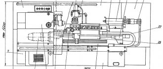
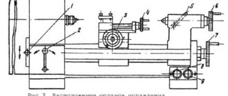
Composition of the STD-120M lathe
Main components of the STD-120M lathe
The machine consists of the following assembly units and parts:
- electric motor
- push button switch
- V-belt drive
- spindle
- headstock
- button block
- lamp
- body with center-fork
- handyman
- protective screen
- clamp handle
- machine guard
- tailstock
- flywheel
- bed with guides
- support foot
- fastening nut
- quill
- center
- stop handle
- holder (carriage)
- double nut
- wooden platform
- support bars
- waste suction slot
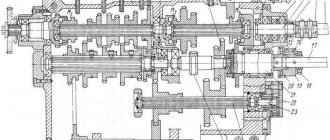
Design of the headstock of the STD-120M lathe
Design of the headstock of the STD-120M lathe
The headstock of the STD-120M lathe is used to install and fasten the workpiece and transmit rotational motion to it.
The headstock consists of a shaped body cast from cast iron. It has two coaxially bored holes for radial spherical bearings.
The spindle is a steel shaped shaft, on the right end of which a thread is cut for screwing on a chuck, faceplate and other special devices for securing workpieces.
At the left end of the spindle there is a two-stage drive pulley, which receives movement through a V-belt transmission from an electric motor. Covers with felt padding are attached to the headstock on both sides.
To start and stop the spindle of the STD-120M machine, a control post is placed on the headstock body, and a lamp is located on top.
V-belt transmission. A two-stage pulley is rigidly attached to the electric motor shaft of the STD-120m lathe, which, using a V-belt, transmits rotation to a two-stage pulley mounted on the spindle of the STD-120 machine. By moving the belt from one stage to another, you can change the spindle speed. The V-belt drive of the STD-120m machine is covered by a metal fence, the opening cover of which is interlocked through a limit switch with an electric motor. When it opens, the electric motor is switched off and the spindle of the STD-120m machine stops.
A two-stage pulley is rigidly fixed to the electric motor shaft, which, using a V-belt, transmits rotation to a two-stage pulley mounted on the machine spindle. The V-belt drive is closed by a metal fence, the opening cover of which is interlocked through a limit switch with an electric motor so that when it is opened, the electric motor is switched off and the machine stops. The guard cover is locked with a screw.
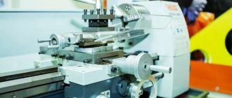
Equipment
For a novice carpenter, the device is equipped with a full set of tools (Maisels, Reiers). The device itself consists of an electric motor, a control unit, a frame, as well as other holding and protective mechanisms. Let's look at the most important of these nodes in more detail.
Front headstock of the unit
The front headstock of the machine is used to secure and hold the part while the engine is running. It is a shaped body cast from cast iron, in which two holes for radial spherical bearings are bored coaxially.
Rear element
The back element or tailstock serves as a support for securing long workpieces, drill chucks, drills themselves, as well as other woodworking tools.
The tailstock consists of a body with a built-in quill that slides along the bed to adjust the length. The required length is fixed using a special bolt that holds the rear element in the desired position.
Main and removable devices
On the STD-120m you can install removable devices to perform various tasks:
- chuck for securing short workpieces at the end;
- center-fork, for installing and processing long parts in the center;
- faceplate.
To secure the workpiece to the outer surface, use the following devices:
- Cup cartridge. It consists of a cylindrical cavity on one side, and a shank for mounting a spindle on the other side.
- Vise chuck. Needed for processing workpieces in the shape of a quadrangle. To work, the workpiece is clamped in a chuck vice and pressed with a screw.
Both types of chucks can have screw threads instead of conical shanks for installation on the outside of the spindle.
Electrical equipment and technical parameters
The STD-120m lathe is equipped with a three-phase asynchronous motor operating on 380V alternating current. The maximum electricity consumption by the motor is 0.4 kW.
The device is controlled by a button block, on which there is a speed switch button, as well as a button to turn off the device.
Inside the control box there is a 380/24 V lighting transformer.
Important!
Do not attempt to repair or disassemble the asynchronous motor of the device yourself. To repair this unit, call a trusted electrical technician.
Devices for securing and processing workpieces on the STD-120M lathe
Devices for securing workpieces on a lathe
- a - spiral self-centering cartridge
- b - cup cartridge
- c - trident
- g - vice chuck
- d - faceplate
- e - cylindrical cartridge
- g - body with a fork center
- z - special cartridge with teeth
- 1 - teeth
- 2 - central tooth
- 3 — fencing of teeth
- 4 - cartridge cone
Depending on the type of workpiece and the work performed, one of the devices included with the machine must be installed on the spindle of the STD-120m machine: a chuck, a center fork or a faceplate. The STD-120M chuck is used to secure short workpieces when processing from the end. The center-fork of the STD-120 machine is designed for securing long wooden workpieces when processing in centers. The faceplate of the STD-120m machine is a metal disk, in the center of which there is a boss with an internal thread for screwing onto the spindle.
Depending on the shape and purpose of the future part, the workpiece is installed in the centers of the headstock and tailstock or on the headstock spindle. In all cases, the workpiece should be positioned so that it can withstand the rotational movement of the spindle. For these purposes, there are many devices that can be divided into the following groups: for securing the workpiece in the centers, for securing the workpiece to the outer surface and for securing the workpiece to the holes.
the trident is most widely used . One end of the trident has the shape of a cone corresponding to the cone in the headstock spindle, and the other end has the shape of a trident fork. When securing the workpiece, one end of it with the intended groove is inserted into the trident, and the second is pressed by the center of the tailstock quill.
To secure the workpiece to the outer surface, the following devices are used: cup, vise and jaw chucks, and a faceplate.
The cup chuck has a cylindrical cavity on one side and a conical shank on the other for installation in the headstock spindle. The rounded part of the workpiece is tightly inserted (hammered) into the cavity of the cartridge or clamped with bolts.
The vice chuck is used in cases where part of the product has the shape of a quadrangle (faceted surface). For processing, the workpiece is inserted into a chuck vice and clamped with a screw. Cup and vice chucks sometimes have screw threads instead of tapered shanks for installation on the outside of the spindle.
To secure products to the outer surface, three-jaw self-centering and four-jaw chucks with independent movement of the jaws are also used. The three-jaw chuck ensures fast and reliable clamping and centering of the workpiece due to the simultaneous radial movement of the jaws. Each three-jaw chuck can be used to secure the product to both the outer and inner surfaces. To do this, such chucks are equipped with two sets of jaws.
For the tailstock, it is advisable to use a self-rotating center (on bearings) with a Morse taper.
Large workpieces and flat disks are processed on the faceplate, for which it has holes through which the workpiece is secured with screws. It must be taken into account that the screws should not extend onto the workpiece surface. The faceplate is screwed onto the spindle after securing the workpiece.
Various frames are widely used for fastening products from holes. Frame designs are chosen depending on the purpose of the product; they are mainly of two types - corrugated and collet.
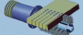
For the production of various parts on a lathe, a cutter-saw is used. This device can be used for cutting rings from aluminum and brass tubes (on a metal lathe) and for cutting blanks made of plastic, plexiglass and other materials.
During operation, the cutter-saw is installed on the machine tool rest so that the bar rests on the workpiece surface to be processed. The cutter is then fed forward evenly. The limiter makes it possible to set the required cutting depth in cases where the workpiece is not cut off at all.
The device is easy to make. The cutter-saw is made from a hacksaw blade. The remaining parts are made of semi-precious steel.
A device for grinding turning products is used when grinding finished products on a lathe. It allows you to achieve good quality grinding, convenient and safe to use. This device is easy to make in any workshop. A plate of porous rubber or felt is glued onto the bar, on top of which sanding paper is applied (preferably on a cloth base). The edges are clamped between the slats using a wing nut. Stopper hooks ensure safe operation. The hooks are attached to the base with a rivet. The device can also be used when polishing products.
Tailstock of lathe STD-120M
Tailstock of lathe STD-120M
The tailstock of the STD-120 machine serves as a support when processing long workpieces, supporting them with the rear center, and for securing a drill chuck, the drills themselves and other tools in its quill when processing holes. The tailstock STD-120 consists of a body with a quill, which slides along the guides of the bed. The tailstock of the STD-120 machine is fixed to the bed guides.
On one side, the quill has a hole bored to a Morse taper, into which the rear center, chucks or drills with a shank with the same taper are inserted. On the other side, a sleeve with internal thread is pressed in. The quill moves freely in the hole in the upper part of the housing. The quill is prevented from rotating around its axis by a set screw that fits into a groove on the outer surface of the quill.
A quill (feed) screw is paired with the threaded bushing, at one end of which a flywheel is mounted on a key and secured with a nut. Rotating with the flywheel, the quill screw moves the quill through a threaded bushing.
The quill is secured in the desired position using the clamp handle. The tailstock is secured with a nut on the frame with a block and a bolt, for screwing which a combination wrench is included. To lubricate the quill and screw, there are oil-conducting holes in the body of the headstock and quill.
Tool rest with holder for lathe STD-120
Tool rest with holder for lathe STD-120
The tool rest with a holder for the STD-120M machine serves as a support for the cutting tool. The tool rest holder consists of a rectangular block with a boss, into the hole of which the tool rest rod is inserted. The tool rest of the STD-120 machine is fixed at the required height and in a certain position with a handle. The tool rest holder is secured to the guides of the STD-120M machine bed with a special screw and a handle through a washer. To work with short and long workpieces, the machine is equipped with two tool rests, 200 mm and 400 mm long.
Bed of lathe STD-120m
The cast iron bed of the STD-120m machine on two legs is installed on a stand and is the base on which the main components of the STD-120M machine are mounted. The front headstock of the machine is fixed to the left of the bed. The holder with a tool rest and the tailstock of the machine are moved along the guides of the frame and secured in a certain position.
Fencing of the cutting zone of the STD-120M machine
The cutting zone fencing on the STD-120m machine serves to protect the worker from flying chips and reduce the concentration of dust generated in the worker’s breathing zone to established sanitary standards. It consists of a metal casing and folding screens.
Devices for installation and fastening of workpieces of the STD-120 lathe
Cutting tools
The machine is equipped with two types of cutting tools: raves and maisols. The rails for the STD-120 machine are a grooved cutter, similar in shape to a semicircular carpenter's chisel. Maisels for the STD-120 machine are cutters that have the shape of a flat chisel with a blade.
Purpose and recommendations for use
The lathe can be used for light wood turning work:
- internal turning and drilling of parts;
- trimming or trimming;
- turning cylindrical figures;
- processing flat surfaces on the faceplate.
The STD-120m is quite unpretentious in operation. However, to reduce the risk of injury, as well as the correct operation of the unit, it is worth following the operating requirements:
- The lathe is installed on a flat and level surface at a height of 500-600 mm from the floor. This could be a workbench or desktop.
- The safety screen on the machine must be lowered during operation. If the machine does not have a chip collection unit, it is necessary to lower the canvas skirt.
- Machine speeds are switched only after the spindle has completely stopped.
- Under no circumstances should you try to move the machine or adjust the workpiece while the motor is running.
- It is strictly prohibited to remove chips, adjust or measure the workpiece, as well as lubricate the device components while the machine is operating! The above actions can only be done after the spindle has completely stopped.
Important!
Install the machine on a flat floor surface, without distortions. To reduce risks and unforeseen situations, place a rubber backing or a sheet of plywood between the legs of the table or workbench and the floor.
It is also worth following the rules of machine maintenance to increase its service life:
- It is necessary to regularly clear chips from the work area. Also, after finishing work, you need to clean the protective screen from fine dust and sawdust.
- After finishing the work, put all the tools in the storage box. Apply neutral lubricant to unpainted areas. For example, on a guide frame.
- Check the condition of the lubrication on all components at least once a year or after 500 hours of operation.
- Upon completion of work, unplug the power cord from the outlet and loosen the tension on the V-belt.
Electrical equipment of the woodworking lathe STD-120M
The electrical equipment of the STD-120 lathe is designed to connect it to a three-phase alternating current network with a voltage of 380 V with a solidly grounded neutral. The control cabinet of the STD-120 lathe also contains a 380/24 V lighting transformer. An asynchronous motor serves as the machine drive. The machine is controlled from the control station located on the front headstock of the machine. The electrical equipment of the STD-120M lathe is connected to a three-phase network with a voltage of 380 V and its grounding is carried out by the Customer. Turning on the machine without connecting it to the grounding line is not allowed.
Advantages and disadvantages
When discussing the pros and cons of the STD 120m machine, it should be taken into account that it was primarily created for training purposes, and the fact that it is also used in some small enterprises already indicates the quality of its assembly and functionality. In addition, the advantages of the machine include:
- Long operating time. The simplicity of the design itself makes it possible for the unit to operate for a long time, but if all components of the machine are carefully and timely maintained, then the period of operation of the machine will increase significantly.
- Relatively small dimensions. This is especially important for classrooms where several devices need to be installed at once.
- High level of security. An indispensable quality for any device that beginners work with. At the same time, a high level of protection will never be superfluous for those who already have work experience and have decided to purchase this machine for their own needs.
- The completeness of training in turning on this machine is guaranteed by the presence of all the necessary devices and functions.
Like any other device, this device has a number of disadvantages:
- The inability to connect to a 220 V network significantly limits the scope of application of the unit.
- Quite small parameters of the processed workpieces reduce the functionality of the device.
- The presence of only two speeds in the device adversely affects the quality of processing of parts.
Republished by Blog Post Promoter
Technical characteristics of the STD-120M lathe
| Parameter name | STD-120M |
| Basic machine parameters | |
| Center height, mm | 120 |
| Maximum length of the workpiece installed in the centers (RMC), mm | 500 |
| Largest diameter of processed workpieces, mm | 190 |
| Maximum length of workpiece turning, mm | 450 |
| Number of spindle rotation speeds, rpm | 2 |
| Spindle speed, rpm | 2350/ 2050 |
| Electrical equipment of the machine | |
| Type of supply current | 380V 50Hz |
| Number of electric motors on the machine, pcs. | 1 |
| Electric motor - rated power, kW | 0,4 |
| Dimensions and weight of the machine | |
| Machine dimensions (length x width x height), mm | 1250 x 575 x 550 |
| Machine weight, kg | 100 |
- Wood lathe (training) STD-120M. Passport, 1990
- Amalitsky V.V. Woodworking machines and tools, 2002
- Afanasyev A.F. Wood carving, Technique, Tools, Products, 2014
- Bobikov P.D. DIY furniture, 2004
- Borisov I.B. Wood processing, 1999
- Jackson A., Day D. Woodworking Bible, 2015
- Golden Book of woodworking for the owner of a country plot, 2015
- Ilyaev M.D. Wood carving, Master's lessons, 2015
- Komarov G.A. Four-sided longitudinal milling machines for wood processing, 1983
- Kondratyev Yu.N., Pitukhin A.V... Technology of wood products, Product design and calculation of materials, 2014
- Korotkov V. I. Woodworking machines, 2007
- Lyavdanskaya O.A., Lyubchich V.A., Bastaeva G.T. Basics of woodworking, 2011
- Lyubchenko V.I. Thicknessing machines for wood processing, 1983
- Manzhos F.M. Wood cutting machines, 1974
- Rasev A.I., Kosarin A.A. Hydrothermal processing and preserving of wood, textbook, 2010
- Ryzhenko V.I. The Complete Encyclopedia of Wood Art, 2010
- Rykunin S.N., Kandalina L.N. Woodworking technology, 2005
- Simonov M.N., Torgovnikov G.I. Debarkers, 1990
- Soloviev A.A., Korotkov V.I. Setting up woodworking equipment, 1987
- Sukhanov V.G. Circular saws for sawing wood, 1984
- Fokin S.V., Shportko O.N. Woodworking, Technologies and equipment, 2017
- Hilton Bill Woodworking, The Complete Guide to Stylish Home Furniture Making, 2017
Bibliography:
Related Links. Additional Information
- Directory of woodworking machines
- Manufacturers of woodworking machines and equipment
- Manufacturers of household woodworking machines
- Manufacturers of chipping machines
- Classification of woodworking machines
- Machines for longitudinal cutting of lumber
- Sawmill frames. Classification
- Lumber. Basic concepts. Terms and Definitions
Home About the company News Articles Price list Contacts Reference information Interesting video KPO woodworking machines Manufacturers