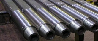
Blanks for drawing
Most often, drawing is used to produce a variety of metal blanks. These can be profiles with a large or medium cross-section, as well as of different shapes. It is recommended to use this processing procedure only if the width and thickness of the original workpiece have a ratio of no more than 20.
In addition, metal drawing is also used in situations where it is necessary for the metal surface to be smooth and clean. Most often, metal products such as profiles with a large or medium cross-section can be extended to a maximum of 6 meters. Metal drawing is relevant for products with a small cross-section and a long length of the workpiece, the ratio between which is no more than 12. Such products usually mean wires made of copper, steel, and aluminum. The use of an operation such as drawing makes it possible to produce wire with a diameter of up to 8 millimeters. It is important to add here that if we are talking about wire processing, then additional processing must be carried out after the drawing operation. This may be additional stretching using special devices or immersion in special compounds.
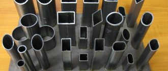
The third and final option for blanks is pipes of any shape and cross-section. Metal drawing is especially effective when you need to make hollow structures. The fact is that this method makes it possible to produce pipe products with thin-walled diameter (0.3-0.4 mm).
Types and methods of drawing
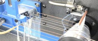
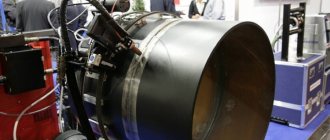
Drawing is performed on a drawing mill.
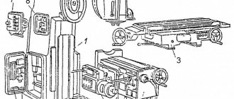
Structurally, the device consists of the following main parts: a die (die), mandrels of various designs, broaching and auxiliary devices for automation and mechanization of the process. In this case, the drawing machine of a rectilinear design is distinguished according to the principle of operation of the main motor of continuous action (track), hydraulic, chain and rope. The process is classified according to the following parameters:
- by type (wet, dry);
- heating the workpiece (cold, hot);
- number of drawn workpieces (1, 2, 4, 8);
- degree of purity of the resulting product (rough, finishing);
- mobility of the drag (stationary, movable);
- number of transitions (single and multiple);
- method of traction (hydraulic, drum, chain).
The variety of parameters has given rise to a huge number of manufactured units, differing in technical characteristics, work technology and productivity.
Drawing is used to produce pipes with a diameter of 0.3÷500 mm with a wall thickness of 0.05÷6 mm. In this case, manufacturing methods can be as follows:
- draft;
- profiling method;
- hydrodynamic friction;
- on a special mandrel (fixed short, long movable, floating);
- on a deformable core;
- with distribution of a pipe-shaped workpiece.
The method, and therefore the equipment for it, is chosen depending on the requirements for the finished product and the brand of the workpiece used. Pipes are manufactured using a chain and drum drawing mill. In the latter case, drawing is called coil drawing.
The essence of the process
The essence of this method is as follows. Metal blanks in the form of strips or strip-type steel with the same cross-section are fed to a drawing machine. The equipment has a certain channel, after passing through which the product acquires the desired geometric shape and size.
The channels are either fairly close in diameter or exactly the same in diameter as the workpieces. It is important to note here that during metal drawing processing, the product is not immediately narrowed to the desired parameters. Throughout the entire channel from its entrance to the exit, the diameter gradually decreases and only at the exit itself is it equal to the indicator that is required to be obtained in the end. It is important to note here that the cross-section of the material that is being pulled will always be larger than the cross-section of the channel of the equipment itself. It is due to this difference that the parameters are effectively changed.
About the essence of the operation, the process of execution
Drawing is the name for the process of drawing workpieces through holes that are tapered. In this case, the source material can be anything:
- Aluminum.
- Steel.
- Copper - it also allows the use of tools such as dies for drawing wire.
A drag is a tool that is used to solve a problem. Die is the name of the hole whose configuration determines the shape of the finished profile after processing.
Compared with rolling by a wire drawer, the drawing technique guarantees improved cleanliness and precision on the wire surface. The same applies to pipes, rods and other parts with different dimensions. After such processing, the characteristics of the material change, only for the better. This is due to the fact that the finished parts receive additional reinforcement.
The technology is especially popular in the manufacture of shaped profiles that require high strength. Successfully produced pipes with different diameters, wires with cross-sections ranging from 1-2 microns to 10 millimeters. Larger figures are also possible. The drawing prism helps to achieve an accurate result.
When using modern drawing technologies, high productivity of the equipment is guaranteed. It's also easy with portages. Even high-speed operations do not prevent you from achieving results constantly, without periodic failures. The amount of compression of the source material remains serious. You just need to use the right wire drawing machine.
The drawing process itself consists of several stages, including:
- First, the raw materials are etched in a sulfuric acid solution, the temperature of which is approximately 50 degrees. This operation is performed to extend the service life of the matrices. The effect is achieved by removing scale from workpieces.
- After the first stage, preliminary annealing of the metal surface is carried out. It is performed with the aim of increasing various characteristics of the source material. This ensures a fine-grained structure at the base. In addition, modern methods protect the wire from damage.
- The aggressive solution is neutralized so that etching can be carried out. After preparation, they are washed. Without this, pipe drawing is impossible.
- The ends of the original metal raw material are sharpened using a hammer or forging wolves.
- Direct drawing process.
- Performing annealing. This is where the pipe drawing ends.
The finished wire can be subjected to additional processing operations, including cutting products to the required lengths, straightening, removing ends, and so on. There are no fingerprints on the products.
This is interesting: Types and features of metal turning
Executing the procedure
Here you need to pay attention to several nuances. To begin with, it is important to know that the processing of metals by pressure (drawing) is carried out on a special installation called a drawing mill. Before starting the broaching procedure, it is necessary to sharpen the end of the workpiece. The procedure must be carried out in such a way that the product can penetrate into the machine channel without any problems and at the same time exit a short distance at the place where it ends. The end that “peeks out” is fixed with a device included in the drawing mill. After this, the process itself starts.
Video and brief description of drawing copper products
The drawing process in the production of copper wire is based on the use of cast blanks. They are first fused and then hot rolled. This process causes a film of oxides to appear on the wire rod. To remove it, the workpiece is treated with dilute acid, and only after that drawing is performed.
Copper wire is also produced using submersible molding technology. In this case, the surface of the wire rod is clean. In this way, the thinnest products (about 10 micrometers) are made. But when performing submersible molding, it is necessary to choose the right lubricant compositions that have high quality and special properties. These include the following lubricants:
- complex solutions: nonionic surfactants, salts (alkaline) of sulfonated fatty oils, alkaline additives;
- emulsions: anti-foam, anionic, stabilizing compounds, synthetic esters, natural fatty and mineral hydrocarbon oil compositions;
- synthetic substances: salts (inorganic and organic), polymer solutions.
Types of drawing operation
Pressing and drawing of metals, like any other operation, has several types of execution:
- Finishing and rough broaching of the workpiece. Naturally, if a finishing broach is performed, it will also become the final broach. This means that the output product will have the necessary parameters, cross-section, and so on. Rough broaching is also called blank broaching.
- Drawing can be multi-thread or single-thread. Everything here is quite simple and clear; with the first method, you can stretch several blanks at once, or rather, up to eight at a time. The only thing worth paying attention to is that the number of threads should always be even, that is, 8, 4, 2.
- There is a metal drawing process called wet drawing. In this case, it is necessary to use a soap emulsion. Dry processing can also be done. In this case, use a container with an emulsion solution.
- The procedure itself can be multiple or single. In other words, this takes into account the number of broaches that the same workpiece has gone through on the mill.
Mandrelless processing method
There are quite a few ways of drawing metals and alloys, and therefore each is worth considering briefly.
A method such as arborless broaching can be used. This method involves working with workpieces made of materials such as non-ferrous alloys and metals, as well as various pipe workpieces. Most often, this method is performed with two dies. One is used to perform cross-sectional compression, and the second is used for alignment. The disadvantage is that the surface greatly loses quality during this procedure, and therefore the method is used only to reduce the diameter of the pipes.
Pipe drawing
During drawing, pipes are produced in several passes with a gradual reduction in diameter and wall thickness. Before drawing the pipes, a number of preparatory operations are performed: inspection, stripping, cutting into pieces, hammering the ends, etching, applying technological coatings and lubricants.
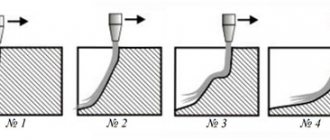
Pipe drawing (Fig. 206) is carried out in several ways: without a mandrel, on a short mandrel, on a long mandrel and on a deformable core.
Drawing without a mandrel is used when it is necessary to reduce only the diameter of the pipe. The deformation is carried out using a die, fixedly fixed in the stop (rest) of the drawing machine. Short mandrel drawing is used to simultaneously reduce the diameter and wall thickness of the pipe.
Currently, the method of drawing on a floating mandrel, a variation of the method of drawing on a short mandrel, has become widespread. The design of all drawing mills is based on a common principle: the use of continuously moving chains to move the pipe during the drawing process. On modern drawing mills, all operations are mechanized. The length of the pipes after drawing is limited by the length of the drawing machine. The most advanced and productive are drawing units, where the pipe production process is carried out on a drum in coils. The length of the pipes can reach 100 mm or more, and the drawing speed is 100 - 200 m/min.
Drawing on continuous drawing machines is a very advanced method of pipe production.
Other pulling methods
When performing the operation, you need to know what values characterize the deformation of the metal during drawing. Such parameters are compression of the thickness of the workpiece, as well as its elongation in relation to the initial size.
You can achieve better quality than with the previous processing method if you use other options:
- Bay. This procedure is considered quite optimal if it is necessary to process pipe blanks made of materials such as copper, brass, aluminum. This means drawing the workpiece wound into a coil. Using the method, it is possible to obtain thin-walled tubes with a thickness from 0.2 to 3 millimeters and a cross-section from 1 to 70 millimeters. Drying oil, water emulsion, vegetable or mineral oils are mandatory compositions, without which such an operation cannot be carried out.
- Carrying out the operation on a mandrel, which can be deformable or fixed.
- One common method is called the rod method. The bottom line is that a rod made of durable steel is inserted inside the workpiece. The broaching operation is carried out along with this rod, which is removed after the entire workpiece has passed through the die. Most often, capillary tubes are made with a cross-section of no more than 1 mm.
It is also possible to draw pipes on drums belonging to the pipe-drawing group, as well as on track mills, which are equipped with chains. The choice of method is based not only on what equipment is available, but also on the properties and type of metal from which the workpiece is made.
Methods for removing scale
The workpiece is freed from scale using different methods. They are often used together.
Chemical
They use solutions of acids - nitric, hydrochloric, phosphoric, hydrofluoric, etc.
Before immersion, the workpiece is subjected to the following types of processing:
- degreasing;
- grinding;
- polishing;
- cutting out defective areas.
Acid solutions are used to remove scale.
The solution is heated to a temperature of +50°C. After processing, the workpiece is washed in water or solvent and dried for 1 hour in an oven at a temperature of +75...+100°C. Properly processed metal becomes matte.
The disadvantage of acid cleaning is that the procedure involves health risks and requires the drawer to have the ability to work with hazardous substances.
Mechanical
The workpiece is bent, twisted and stretched, and then processed with tools:
- abrasive brushes;
- needle cutters;
- micro-cutting devices.
The workpiece is treated with abrasive brushes.
Electrochemical
Acid etching is combined with the action of direct electric current.
There are 2 types of method:
- Anodic. The positive pole of the current source is connected to the workpiece. As a result, oxygen accumulates on it, which leads to the detachment of oxides. The method is used to remove thin films from the surface of alloy and carbon steel.
- Cathode. The negative pole is connected, as a result hydrogen accumulates on the workpiece. It reduces iron oxides. This is a more dangerous method: scale detachment cannot be precisely controlled, and the metal often becomes brittle.
Combined
It involves a combination of chemical and electrochemical methods. The combined method is used in the most difficult cases.
Special mills for broaching
Metal can be processed by drawing in several passes. The picture will be presented for illustrative purposes.
As for the blanks, they are most often made of non-ferrous metal and steel. The initial section can be equal to 0.01 mm. The equipment differs in the type of die that is installed on it. Let's say that mills with diamond dies are used only for the thinnest products. Carbide die is used for medium and thick workpieces. Steel equipment is used only for working with the largest products.
The design of the mills itself can also differ quite a lot. Some of them can reach processing speeds of up to 50 meters per second. Others may be equipped with more than two dozen portages at once. Certain designs allow you to work both with and without sliding. Drums for coil processing can be horizontal or vertical; there may be an individual or group type electric drive.
Lecture 9. Pressing and drawing
Pressing
Pressing
– a type of pressure treatment in which metal is squeezed out of a closed cavity through a hole in the matrix corresponding to the cross-section of the profile being pressed.
This is a modern method of producing various profile blanks: rods with a diameter of 3...250 mm, pipes with a diameter of 20...400 mm with a wall thickness of 1.5...15 mm, profiles of complex sections, solid and hollow, with a cross-sectional area of up to 500 cm2.
The method was first scientifically substantiated by Academician N.S. Kurnakov in 1813 and was used mainly for the production of rods and pipes from tin-lead alloys. Currently, ingots or rolled products from carbon and alloy steels, as well as from non-ferrous metals and alloys based on them (copper, aluminum, magnesium, titanium, zinc, nickel, zirconium, uranium, thorium) are used as the initial workpiece.
The technological process of pressing includes the following operations:
preparing the workpiece for pressing (cutting, preliminary turning on a machine, since the quality of the workpiece surface affects the quality and accuracy of the profile); heating the workpiece followed by descaling; placing the workpiece in a container; the pressing process itself; finishing of the product (separation of press residue, cutting).
Pressing is carried out on hydraulic presses with a vertical or horizontal plunger arrangement, with a capacity of up to 10,000 tons.
Two pressing methods are used: direct
and
reverse
(Fig. 15.)
During direct pressing, the movement of the press punch and the flow of metal through the die hole occur in the same direction. With direct pressing, much more force is required, since part of it is spent on overcoming friction when moving the metal of the workpiece inside the container. The press residue is 18...20% of the workpiece weight (in some cases - 30...40%). But the process is characterized by a higher surface quality, and the pressing scheme is simpler.
Rice. 15. Scheme of pressing a rod using the direct (a) and reverse (b) method
1 – finished rod; 2 – matrix; 3 – workpiece; 4 - punch
During reverse pressing, the workpiece is placed in a blind container, and during pressing it remains motionless, and the outflow of metal from the hole of the matrix, which is attached to the end of the hollow punch, occurs in the direction opposite to the movement of the punch with the matrix. Reverse pressing requires less effort, the press residue is 5...6%. However, less deformation results in the extruded rod retaining traces of the cast metal structure. The design is more complex
The pressing process is characterized by the following main parameters: elongation coefficient, degree of deformation and speed of metal flow from the matrix point.
The main advantages of the process include:
· the ability to process metals that cannot be processed by other methods due to low ductility;
· the ability to obtain almost any cross-sectional profile;
· obtaining a wide range of products on the same pressing equipment with only the replacement of the matrix;
· high productivity, up to 2…3 m/min.
Disadvantages of the process:
· increased metal consumption per unit of product due to losses in the form of press residue;
· the appearance in some cases of noticeable unevenness of mechanical properties along the length and cross-section of the product;
· high cost and low durability of the pressing tool;
· high energy intensity.
Technical and economic indicators of obtaining products by pressing
Drawing
The essence of the drawing process is to pull workpieces through a tapering hole (die) in a tool called a die. The configuration of the hole determines the shape of the resulting profile. The drawing diagram is shown in Fig. 16.
Fig. 16. Drawing scheme
Wire with a diameter of 0.002...4 mm, rods and profiles of shaped cross-section, thin-walled pipes, including capillary ones, are produced by drawing. Drawing is also used to calibrate the section and improve the surface quality of processed products. Drawing is often performed at room temperature, when plastic deformation is accompanied by hardening; this is used to increase the mechanical characteristics of the metal, for example, the tensile strength increases by 1.5...2 times.
The starting material can be hot-rolled rod, rolled steel, wire, pipes. Steels of various chemical compositions, non-ferrous metals and alloys, including precious ones, are processed by drawing.
The main tool for drawing is dies of various designs. Dies work under difficult conditions: high stress is combined with wear during broaching, which is why they are made of hard alloys. To obtain particularly precise profiles, dies are made of diamond. The design of the tool is shown in Fig. 17.
Fig. 17. General view of the die
The die 1 is fixed in the holder 2. The dies have a complex configuration, its components are: intake part I, including an input cone and a lubricating part; deforming part II with an angle at the apex (6...18 0 - for rods, 10...24 0 - for pipes); cylindrical calibrating belt III 0.4…1 mm long; exit cone IV.
The technological process of drawing includes the following operations:
preliminary annealing of workpieces to obtain a fine-grained metal structure and increase its ductility; etching of workpieces in a heated solution of sulfuric acid to remove scale, followed by washing; after removing scale, a lubricating layer is applied to the surface by copper plating, phosphating, liming, the lubricant adheres well to the layer and the friction coefficient is significantly reduced; drawing, the workpiece is sequentially pulled through a series of gradually smaller holes; annealing to eliminate hardening: after 70...85% reduction for steel and 99% reduction for non-ferrous metals; finishing of finished products (trimming ends, straightening, cutting to lengths, etc.)
The technological process of drawing is carried out on special drawing mills. Depending on the type of pulling device, mills are distinguished: with linear movement of the drawn metal (chain, rack); with winding of the processed metal on a drum (drum). Drum-type mills are usually used to produce wire. The number of reels can reach up to twenty. The drawing speed reaches 50 m/s.
Technical and economic indicators of the operation of drawing mills.
Wire drawing options
In fact, there are several options for performing even such a simple operation as drawing wire.
- There is an option in which the wire grip is not needed. The workpiece moves forward due to the force applied from the reverse side. The method is called non-clogging method.
- There is a method called hydrodynamic. In this case, the use of combined type equipment is implied. This equipment includes a mounting ring, a pressure die, and a working die. The mill is driven by high pressure pumps. The problem is that the installation, as well as the use of this mill, is too expensive in terms of cost. For these reasons, it is used only if the use of other, simpler options is impossible.
About other important features of the procedure
According to experts, the technology has only one significant drawback. This is that the wire deformation rate is too small. This happens due to the limitation caused by the strength of the exit end of the workpiece. Whatever deformation force is applied, this is the result we get. Drawing marks are also different.
The starting material must always be rolled, pressed, or continuously cast. This applies to carbon and alloy steels, non-ferrous metals. Casting will be of high quality only if there is a certain structure at the base. Then you can forget about traces of stains.
Patenting is a technology that has always been used for steel wires in the past. In this procedure, the material was first heated to the austenitizing temperature. And then the exposure was carried out using molten salt or lead. The exposure involved maintaining the temperature at approximately 500 degrees Celsius. This is also different from drawing.
Nowadays, you can do without such complex procedures. When leaving the rental equipment, it has become much easier to ensure the required characteristics. Each machine is equipped with a specialized cooling system. Nowadays, work processes cannot be completed without soap shavings for dry drawing.
What can be produced at the mill
Drawing mills can easily produce square, round or hexagonal rods. In this case, they will be of the cold-deformed type. It is important to note here that even minor changes in the technological process of the procedure make it possible to produce different workpieces. Large products - with a cross-section of more than 3 cm, small rods - with a cross-section of less than 2.5 cm. The most standard processing scheme looks like this: the product in a coil is placed on the mill, and then the drawing procedure is performed. In standard processing this is always a single drawing. After this, the structure is sent to an automatic line, where it usually undergoes the final stage of processing.
Main stages of the process
The final product obtained by drawing is subject to certain requirements, which are indicated in the technological characteristics. The workpiece goes through certain stages that affect the final result. They are as follows:
- annealing of the workpiece to obtain a fine-grained structure and increase plastic properties;
- removing scale from the workpiece surface;
- washing the workpiece after etching in a sulfuric acid solution;
- applying a special layer, the composition of which depends on the material of the workpiece;
- drawing on the mill;
- elimination of hardening;
- finalization of the resulting products (trimming to the required length, finishing the ends).
As a rule, they affect the density, hardness, fluidity, electrical resistance of the material (increase), plastic, anti-corrosion properties (decreases). This manifestation, called cold hardening, is eliminated by heat treatment - normalization, patenting, tempering, annealing. The choice of method depends on the grade of metal or alloy and the conditions of the drawing process.
Special types of broaching
Since today technology has developed quite significantly, sometimes drawing can be performed using one of two innovative technologies. The first is called electroplastic. The method is based on the principle that if an electric current is passed through the workpiece during drawing, the effort required for drawing is significantly reduced. This innovative method is used most often when processing alloys, which themselves are quite difficult to deform.
The ultrasonic method is used in particular for those structures that, due to their initial characteristics, are prone to such disadvantages as deformation aging, as well as a decrease in plastic properties when heated.