Information about the manufacturer of the CNC lathe 16A20F3
Manufacturer of the CNC lathe 16A20F3 - Moscow Machine Tool Plant named after. A.I. Efremova , founded in 1857.
The first universal screw-cutting lathes with a gearbox for the first time in the USSR began to be produced at the Moscow Machine Tool Building named after. A.I. Efremov in 1932 and received the names DIP-200, DIP-300, DIP-400, DIP-500 ( DIP
- Catch up and Overtake), where 200, 300, 400, 500 is the height of the centers above the frame.
As the design of the machines improved, the plant produced more and more modern models - 1A62, 1K62, 16K20, MK6056.
Machine tools produced by the Moscow Machine Tool Plant Krasny Proletary, KP
- 1A62
- universal screw-cutting lathe Ø 400 - 1K62
- universal screw-cutting lathe Ø 400 - 1K62B
- universal screw-cutting lathe with increased accuracy Ø 400 - 1K282
- eight-spindle vertical lathe Ø 250 - 1K620
- universal screw-cutting lathe with variator Ø 400 - 1K625
- lightweight screw-cutting lathe with an increased line of centers Ø 500 - 16A20F3
– CNC lathe Ø 400 - 16B20P
- high-precision screw-cutting lathe Ø 400 - 16K20
– universal screw-cutting lathe Ø 400 - 16K20M
- mechanized screw-cutting lathe Ø 400 - 16K20P
- high-precision screw-cutting lathe Ø 400 - 16K20F3
– CNC lathe Ø 400 - 16K20F3S32
– CNC lathe Ø 400 - 16K20T1
- lathe with operational control Ø 500 - 16K25
- lightweight screw-cutting lathe with an increased line of centers Ø 500 - 162
— universal screw-cutting lathe Ø 420 - 1730
— semi-automatic multi-cutting lathe Ø 410 - DIP-40 (1D64)
- universal screw-cutting lathe Ø 800 - DIP-50 (1D65)
- universal screw-cutting lathe Ø 1000 - DIP-200
– universal screw-cutting lathe Ø 400 - DIP-300
– universal screw-cutting lathe Ø 630 - DIP-400
– universal screw-cutting lathe Ø 800 - DIP-500
– universal screw-cutting lathe Ø 1000 - MK6046, MK6047, MK6048
- universal screw-cutting lathe Ø 500 - MK6056, MK6057, MK6058
- universal screw-cutting lathe Ø 500 - MK-3002
- table lathe Ø 220
Manufacturer information
Near the workshop in Zamoskvorechye, the Bromley brothers began construction of a mechanical plant in 1857. His first products were axes, sickles and other tools for peasants. In 1864, the brothers purchased a new plot and began to obtain permission to build new workshop buildings.
In 1870 and 1872, planing and drilling machines from Zamoskvorechye received gold medals at the Moscow Industrial Exhibition. The triple expansion steam engine was awarded the Grand Gold Medal at the International Exhibition in Paris.
In 1918, the plant was nationalized and modernized. Since 1922, the plant has completely switched to the production of metal-cutting machines. In 1971, the first machines of the 16K20 series were produced. After the reconstruction of the plant, in 1973 they began to produce 16A20F3 with CNC.
Important!
Since 2021, the Moscow Machine Tool Plant has been located in New Cheryomushki. The production of CNC lathes has resumed.
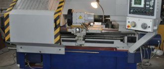
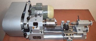
General view of the CNC lathe 16A20F3
Photo of CNC lathe 16a20f3
Photo of CNC lathe 16a20f3
Photo of CNC lathe 16a20f3
Photo of CNC lathe 16a20f3
Operator's manual for screw-cutting lathe 16А20Ф3 with CNC 2Р22
This manual contains information for the operator on servicing the 16A20F3 S32 machine with a 2P22 or 2P22.01 CNC system. Contents of the operator's manual:
- Purpose of the program
- Program execution conditions
- Program Execution
- Operating procedure
- General provisions
- Linking the device to machine parameters
- Linking the reference system to the machine
- Linking a tool to a reference system
- Linking a reference system to a part
- Semi-automatic input of the initial position and exit of the tool to this position
- Input mode
- Program output
- Manual control mode
- Automatic mode
- Test mode
- Coding system and frame order
- Programming chamfers, arcs and fillets
- Programming canned cycles
- Drawing up programs when entering from punched tape
- Messages to the operator
- Device exchange signals
- Algorithms for the operation of electrical automation of a controlled machine
You can download the “Operator’s Manual for the 16A20F3 CNC 2P22 CNC lathe” (85 sheets) for free in good quality using the link below.
You can download for free “Instructions for programming a screw-cutting lathe 16A20F3 with CNC 2P22” (3 sheets) in good quality from the link below.
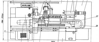
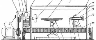
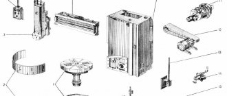
Location of the components of the machine 16A20F3
Location of the main components of the machine 16a20f3
Location of the main components of the machine 16a20f3
| # | Name | Designation | ||
| 16A20F3S15 | 16A20F3S32 | 16A20F3S39 | ||
| 1 | Base with chip conveyor | 16K20F.013000.000 | ||
| 2 | bed | 16K20T1.010000.000 | ||
| 3 | Support group | 16K20T1.054000.000 | ||
| 4 | Transmission of VGK longitudinal movement | 16K20T1.159000.000 | ||
| 5 | Left support for longitudinal screw | 16K20T1.072000.000 | ||
| 6 | Power chuck with electromechanical drive | 16K20F.092000.000 | ||
| 7 | Fence is fixed | 16A20F3.268000.000 | ||
| 8 | Movable fence | 16A20F3.265000.000 | ||
| 9 | Spindle head | 16A20F3.025000.000 | ||
| 10 | Control cabinet for machine | 16A20FZ.180000 | 16A20F3.447000 | 16A20FZ.192000 |
| 11 | Automatic 8-position head | UG9326.000000 | ||
| 12 | Support group guard | 16A20F3.267000.000 | ||
| 13 | Tailstock | 16A20F3.035000.000 | ||
| 14 | Electromechanical tailstock quill drive | 16A20F3.037000.000 | ||
| 15 | Communications layout | 16A20F3.112000.000 | ||
| 16 | Machine control panel | 16A20F3.513000 | 16A20F3.510000 | 16A20F3.509000 |
| 17 | Control panel bracket | 16A20F3.511000.000 | ||
| 18 | Right longitudinal support | 16K20T1.073000.000 | ||
| 19 | Headstock lubrication station | 16K20T1.241000.000 | ||
| 20 | Motor installation | 16K20T1.157000.000 | ||
| 21 | Rear area guard | |||
| 22 | Lateral drive | 16K20Tl.486000.000 | ||
| 23 | Transmission of VGK transverse movement | 16K20T1.158000.000 | ||
| 24 | Box as part of the unit | 16A20F3.447000.000 | ||
Location of controls for lathe 16A20F3
Location of controls for lathe 16a20f3
List of controls for the 16A20F3 lathe
- Machine control panel
- Spindle speed range setting handle
- Handle for manual movement (approach - removal) of the transverse support
- Drive control panel Size 2M-5-21
- Machine operation control panel
- Tailstock clamping handle on the machine
- Chip conveyor control panel
- Handle for manual movement (left - right) of the longitudinal carriage
- CNC keyboard
- Tailstock quill input and output control pedal (double)
- Control pedal for clamping and releasing the chuck (double)
- BOSI block for displaying symbolic information. Visualization of the processing program, tool correction
- Tailstock quill clamp handle
Electrical circuit diagram of a screw-cutting lathe 16A20F3 with CNC 2P22
Below are sketches of two pages of the electrical circuit diagram of a 16A20F3 screw-cutting lathe with a 2P22 CNC device, a KEMROS main drive and a KEMTOR electric feed drive.
You can download a free electrical circuit diagram of a screw-cutting lathe 16A20F3 (21 sheets) in good quality from the link below. This machine uses an electric drive for the main movement KEMROS and an electric drive for feeds KEMTOR , so here are links to the documentation on these electric drives.
Kinematic diagram of a CNC lathe 16A20F3
Kinematic diagram of the lathe 16a20f3
The kinematic diagram of the machine is shown in Fig. 21. Kinematic diagrams of the automatic head and chip removal conveyor are given in their operating manuals.
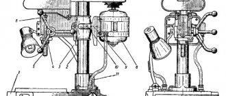
Main movement mechanism of the machine
The machine is equipped with a 16A20F3.025 spindle head. (Fig. 22), having three ranges with a ratio of 1.25:1; 1:2; 1:5.8; manually switchable. The range of rotation speeds and handle positions are shown in table. 18.
The permissible imbalance values when processing a product at various rotation speeds are given in table. 19.
The values of power and torque on the spindle at various rotation speeds are given in table. 20.
The machine spindle is mounted in double-row and single-row conical bearings. Bearings are adjusted at the machine manufacturer's factory and do not require adjustment during operation.
The position of the spindle head axis on the frame is adjusted using two screws (Fig. 23).
The spindle head is lubricated from a lubrication station mounted on the base of the machine. To ensure the possibility of thread cutting, a thread cutting sensor 1 is installed on the spindle head (see Fig. 22). To sample the gap in the meshing of gears 2, 3 of the sensor drive, turn the eccentric flange 4.
A frequency-controlled asynchronous electric motor with a control range with a constant power of 1500...4500 rpm (1000...3500 with DC motors made in Bulgaria) is used as the main movement drive.
The transmission of rotation from the electric motor to the first shaft of the spindle head is carried out by a 2240L20 poly V-belt with a gear ratio of 115:257 (160:257 in the case of using a DC electric motor manufactured by NRB).
The base of the machine is a rigid casting. The base, the electric motor of the main movement, lubrication stations for the guides of the carriage and the spindle head are installed on the base. Two types of bases are used:
- with a window for chip collection and an opening for installing a chip removal conveyor, which is inserted from the right side;
- without a window, divided vertically in the middle part by a solid partition, in this case the middle part of the base serves as a collector for chips and coolant, the compartment in the lower right part of the base serves as a coolant reservoir, and a coolant pump is installed at the rear on the right side of the base.
Passport for screw-cutting lathe 16A20F3
This operating manual “ Passport of the machine 16A20F3 ” contains information necessary both for the maintenance personnel of this machine and for the employee directly involved in working on this machine. This manual is an electronic version in PDF format of the original paper version. This documentation contains the Passport and Manual (instructions) for the operation of the universal screw-cutting lathe 16A20F3.
Content :
- GENERAL INFORMATION ABOUT THE EQUIPMENT
- MAIN TECHNICAL DATA AND CHARACTERISTICS
- COMPLETENESS
- SAFETY INSTRUCTIONS
- PART OF THE EQUIPMENT
- INSTALLATION PROCEDURE
- DESIGN AND OPERATION OF EQUIPMENT AND ITS COMPONENTS
- HYDRO- AND PNEUMATIC LUBRICATION SYSTEM
- OPERATING PROCEDURE
- INSTRUCTIONS FOR MAINTENANCE, OPERATION AND REPAIR
- POSSIBLE MALFUNCTIONS AND METHODS OF THEIR ELIMINATION
- FEATURES OF DISASSEMBLY AND ASSEMBLY DURING REPAIR
- SPARE PARTS INFORMATION
- MANUFACTURER'S WARRANTY
You can download the passport of the screw-cutting lathe 16A20F3 (54 sheets) in excellent quality from the link below. Since this machine is built on a 2P22 CNC device, in addition to this passport, various documentation on the 2P22 CNC is required.
16A20F3 Lathe design
Machine bed
The machine bed has a box-shaped shape with transverse ribs of a U-shaped profile, hardened ground guides. The following are installed on the machine bed: spindle head, carriage, longitudinal feed drive, tailstock.
To base the carriage on the frame, the front guide has the shape of an unequal prism, the rear guide is flat. The tailstock is based on the frame along a small rear prismatic guide and along a plane on the front guide.
Longitudinal drive
The longitudinal movement drive (Fig. 24, 25) includes a ball screw-nut transmission, screw supports, a DC drive motor or an asynchronous frequency-controlled motor, as well as a feedback sensor connected to the screw through couplings, on 16L20FZS39 machines with a “drive” Size 2M-5-21" uses a sensor built into an asynchronous motor. The drive provides an additional transmission to the manual roller, which is used to move the carriage during painting, preservation and re-preservation of the disabled machine.
Lateral drive
The transverse drive includes:
- ball drive
- rolling screw nut
- screw support
- drive motor DC or asynchronous with frequency regulation
- feedback sensor connected to the propeller through couplings
On 16A20FZS39 machines with a “Size 2M-5-21” drive, a sensor built into an asynchronous electric motor is used. The drive provides an additional transmission to the roller for manual movement of the caliper during painting, preservation or re-preservation of a switched off machine.
On machines without a sensor, this gear and roller are not installed; the caliper should be moved with a key by the head of the screw screwed into the end of the transverse movement screw.
Automatic universal head
The machines use a 6-, 8- and 12-position automatic universal head with a horizontal axis of rotation with a tool disk for 6 radial and 3 axial tools (6-position) or 8 blocks for radial or axial tools (8-position) or 12 for radial tools and blocks for axial tools, combined when setting up a part (12-position). For a description of the head, see the operating manual for the head. On top of the D head there is a valve for regulating the coolant supply, which is turned when setting up the machine.
Tailstock
Using handle 7, eccentric shaft 1, clamping bar 4 and a lever system, the tailstock is secured to the frame. If handle 7, retracted to the rear position, does not provide sufficient clamping of the headstock to the frame, then it is necessary to set the required clamping force by adjusting screws 3 and 6 with lock nuts 2 and 5 released, changing the position of the clamping bar 4. The movement of the quill is carried out by the drive of the electromechanical movement of the quill from the EMG51 head.
Machines designed for PMG are equipped with a quill movement drive with control of the quill position; for this purpose, limit switches are installed on the tailstock, which are activated when the quill moves and give signals about the position of the quill in the automatic cycle of operation of the machine with the robot.
If a part is missing or incorrectly installed, the quill passes through the working position, the cam releases the limit switch, and the command to continue the automatic cycle is not issued.
The limit switch control cams are mounted on a rotary shaft connected to the quill movement screw through a worm-helical gear transmission and can be adjusted to suit a specific part.
The quill “retraction” position cam is usually not adjustable; the quill “pressure” cam is set so that the limit switch is activated 2 mm before the end of the workpiece. The permissible axial force on the center of the tailstock is 10 kN (1000 kgf).
The fence is fixed, panel type with removable shields on the rear side of the machine, and the front fence is movable with a transparent screen for observation, covering the cutting area.
In order to control the position of the fence, limit switches are installed, which provide signals for the operation of the machine in an automatic cycle with the robot. In the extreme positions of the fence, movement is slowed down.
Recommendations for installation and use of cartridges
To control the position of the rod on the headstock, contactless limit switches 13 are installed on the bracket 12, which give signals about the position of the movable ring 11 and the drive rod of the chuck cams in the automatic cycle of operation of the machine with the robot.
Motor installation
The main drive motor (asynchronous frequency-controlled or DC) is mounted on a plate (Fig. 29), secured with three screws on the base of the machine. To move the plate vertically when putting on and tensioning the belt, rod 3 with nuts 2 is used.
Contact indicator drive
On machines designed for embedding into a hydraulic machine, a contact indicator of type BV-427100 000-07 is installed upon special order. Indicator 1 (Fig. 30) is fixed on a rotating bracket 2, which is rotated into a horizontal working or vertical retracted position by the rack-rod 3 of the hydraulic cylinder 4. The rotation of the lever to the working position is limited by a stop 5. The arrival of the lever in the working and retracted position is controlled by contactless electric switches. The signal received from the contact indicator when touching the working edge of the tool enters the CNC when operating in the mode with automatic tool binding. When the lever is lowered, it opens the spring-loaded rotary door 6, which protects the contact indicator from chips when the machine is operating. Depending on the design of the machine’s electrical circuit, instead of contactless electric switches, microswitches of the MP-1000 series can be installed.
Support group
The design of the caliper group is distinguished by the use of combined transverse guides - left inclined, right - rectangular and the coating of the working surfaces of the longitudinal guides of the carriage and the transverse guides of the caliper with an antifriction composition, for example, UP5221 produced by NPO "Plastpolymer" (Donetsk, Voroshilovgrad region). The anti-friction coating ensures a constant coefficient of friction at low and high speeds of working movements, which improves positioning accuracy and stability and precision of processing.
Remote Control
The control panel is mounted on a rotating bracket 5, fixed to the base of the machine and is rotated by the operator when setting up the machine to a position convenient for him, depending on the length of the workpiece. The console contains panels with machine controls, as well as a CNC keyboard (on a folding panel), a computing unit and an external memory device for the CNC “Electronics NTs-31” or a symbolic information display unit for the CNC 2P22 or CNC MC2101. Controls on the panels (see above), operation of the keyboard is described in the accompanying documentation on the CNC and programming instructions. When transporting the machine, breaks in work, stopping for a lunch break, etc., you should lift the folding panel to the upper, closed position and lock it with the lock provided in the design of the remote control. After debugging the control program, it is necessary to turn the remote control and the rotary bracket away from the machine so that when the longitudinal carriage of the machine is retracted to the extreme right position and the transverse support to the extreme retracted position, the support and the body of the automatic head cannot touch the control panel.
Specifics of the machine design
Appearance
Before considering the technical characteristics of the machine, you should familiarize yourself with the features of its design. Machines 16A20F3 with a numerical control unit are designed for processing workpieces by rotating them in a semi-automatic mode in a closed cycle.
To complete turning equipment, you can use various types of CNC, the characteristics of which are selected depending on production requirements. These can be open-loop, closed-loop or CNC modules. The design of the 16A20F3 machine is designed to connect these blocks.
The layout features include the following nuances:
- cast iron bed. It is made of SCh20 cast iron; on its surface there are polished guides that have undergone heat treatment;
- improved main drive characteristics. The electric motor power of 11 kW makes it possible to provide a maximum torque for the spindle head of 800 Nm;
- Increased component protection measures. First of all, this applies to ball screws designed for displacement along the X and Z coordinates. It is possible to equip them with electric drives from foreign manufacturers.
For simultaneous processing of several planes of the workpiece in the 16A20F3 machine with a CNC unit, you can mount removable cutter holders designed to install 6, 8 or 12 cutting tools.
Currently, the manufacturer offers standard equipment. But at the request of the customer, the 16a20f3 machine can be equipped according to the requirements for a specific production.
Technical characteristics of the machine 16A20F3
| Parameter name | 16K20F3S32 | 16A20F3S32 | 16A20F3S39 |
| Basic machine parameters | |||
| CNC system designation | 2Р22 | 2Р22 | NTs-31-02 |
| The largest diameter of the workpiece above the bed, mm | 400 | 320 | 320 |
| The largest diameter of the workpiece above the support, mm | 220 | 200 | 200 |
| The largest diameter of the installed product above the frame, mm | 500 | 500 | 500 |
| Spindle hole diameter, mm | 53 | 55 | 55 |
| Maximum length of the product installed in centers (RMC), mm | 1000 | 1000 | 1000 |
| Maximum length of the workpiece with the number of tool head positions (6, 8, 12), mm | 870 | 900,750,850 | 900,750,850 |
| Spindle | |||
| Main movement motor power, kW | 11 | 11 | 11 |
| Number of spindle speeds | 22 | ||
| Spindle speed limits, rpm | 12,5…2000 | 20…2500 | 20…2500 |
| Spindle speed range, manually set, rpm | Row I - 12.5..200 Row II - 50..800 Row III - 125..2000 | Row I - 20...345 Row II - 60...1000 Row III - 145...2500 | Row I - 20...345 Row II - 60...1000 Row III - 145...2500 |
| Number of automatically switched speeds | 9 | ||
| Automatic switching range | 16 | ||
| Headstock spindle center according to GOST 13214-67 | Morse No. 6 | Morse No. 6 | Morse No. 6 |
| Tailstock quill center according to GOST 13214-67 | Morse No. 5 | Morse No. 5 | Morse No. 5 |
| Spindle end according to GOST 12593-72 | 6K | 6K | 6K |
| Maximum torque on the spindle, not less than, Nm (kgf*m) | 800 (80) | 800 (80) | |
| Submissions | |||
| Maximum movement of the caliper: longitudinal (Z) / transverse (X), mm | 900/ 250 | 905/ 210 | 905/ 210 |
| Limits of pitches of cut threads, mm | 0,1..39,999 | 0,25…40 | 0,25…40 |
| Range of longitudinal feed speeds, mm/min (mm/rev) | 3..2000 | 10..2000 (2,8) | 10..2000 (2,8) |
| Transverse feed speed range, mm/min (mm/rev) | 3..2000 | 5..1000 (1,4) | 5..1000 (1,4) |
| Speed of fast longitudinal/transverse strokes, m/min | 7,0/ 4,0 | 15/ 7,5 | 15/ 7,5 |
| Cutter height, mm | 25 | 25 | 25 |
| Number of positions on the rotary toolholder (number of tools in the turret) | 6 | 8 (6,12) | 8 (6,12) |
| CNC system parameters | |||
| CNC system designation | 2Р22 | 2Р22 | NTs-31-02 |
| Number of coordinates | 2 | 2 | 2 |
| Number of simultaneously controlled coordinates | 2 | 2 | 2 |
| Discreteness of setting coordinates in the longitudinal/transverse direction (discreteness of setting along the Z, X axis) | 0,001 | 0,001 | 0,001 |
| Limits of programmable longitudinal/transverse feeds, mm/rev | 0,01…20/ 0,01..10 | 0,01…20/ 0,01..10 | 20,01…40/ 0,01..20 |
| Position and thread feedback sensor type | ROD-620 | BE178A5 | BE178A |
| Electrical equipment of the machine | |||
| Main drive electric motor, kW/rpm | 11/ 1460 | 11/ 1500 | 11/ 1500 |
| Electric motor of longitudinal feeds - rated torque, Nm (kgf*m) | 23 (2,3) | 23 (2,3) | |
| Cross feed electric motor - rated torque, Nm (kgf*m) | 17 (1,7) | 17 (1,7) | |
| Electric motor of the carriage lubrication station, kW/rpm | 0,18/ 1400 | 0,18/ 1400 | |
| Electric motor of the spindle head lubrication station, kW/rpm | 0,27/ 1450 | 0,27/ 1450 | |
| Cooling pump electric motor, kW/rpm | 0,12/ 2800 | 0,12/ 2800 | |
| Electric motor of the tool head, kW/rpm | 0,37/ 1365 | 0,37/ 1365 | |
| Total power of electric motors, kW | 20 | 21,4 | 21,4 |
| Total power of the machine, kW | 22 | 24 | 24 |
| Dimensions and weight of the machine | |||
| Overall dimensions of the CNC machine (length, width, height), mm | 3700 1700 2145 | 3700 3000 2100 | 3700 3000 2100 |
| Weight of CNC machine, kg | 4050 | 4150 | 4150 |