Information about the manufacturer of the lathe 16K20t1
Manufacturer of the 16K20t1 lathe - Moscow Machine Tool Plant named after. A.I. Efremova , founded in 1857.
The first universal screw-cutting lathes with a gearbox for the first time in the USSR began to be produced at the Moscow Machine Tool Building named after. A.I. Efremov in 1932 and received the names DIP-200, DIP-300, DIP-400, DIP-500 ( DIP
- Catch up and Overtake), where 200, 300, 400, 500 is the height of the centers above the frame.
As the design of the machines improved, the plant produced more and more modern models - 1A62, 1K62, 16K20, MK6056.
Machine tools produced by the Moscow Machine Tool Plant Krasny Proletary
- 1A62
- universal screw-cutting lathe Ø 400 - 1K62
- universal screw-cutting lathe Ø 400 - 1K620
- universal screw-cutting lathe with variator Ø 400 - 1K282
- eight-spindle vertical lathe Ø 250 - 1K625
- lightweight screw-cutting lathe with an increased line of centers Ø 500 - 16A20F3
– CNC lathe Ø 400 - 16B20P
- high-precision screw-cutting lathe Ø 400 - 16K20
– universal screw-cutting lathe Ø 400 - 16K20M
- mechanized screw-cutting lathe Ø 400 - 16K20P
- high-precision screw-cutting lathe Ø 400 - 16K20F3
– CNC lathe Ø 400 - 16K20F3S32
– CNC lathe Ø 400 - 16K20T1
- lathe with operational control Ø 500 - 16K25
- lightweight screw-cutting lathe with an increased line of centers Ø 500 - 162
— universal screw-cutting lathe Ø 420 - 1730
— semi-automatic multi-cutting lathe Ø 410 - DIP-40 (1D64)
- universal screw-cutting lathe Ø 800 - DIP-50 (1D65)
- universal screw-cutting lathe Ø 1000 - DIP-200
– universal screw-cutting lathe Ø 400 - DIP-300
– universal screw-cutting lathe Ø 630 - DIP-400
– universal screw-cutting lathe Ø 800 - DIP-500
– universal screw-cutting lathe Ø 1000 - MK6046, MK6047, MK6048
- universal screw-cutting lathe Ø 500 - MK6056, MK6057, MK6058
- universal screw-cutting lathe Ø 500 - MK-3002
- table lathe Ø 220
Passport for screw-cutting lathe 16K20
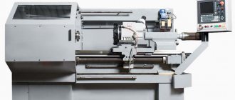
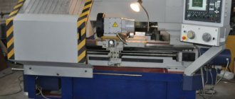
Moscow Efremov Machine Tool Plant, operating manual, 16K20.000.000.RE, 1979. The screw-cutting lathe model 16K20 is designed for performing various turning operations and cutting metric, modular, inch and pitch threads. The workpieces are mounted on centers or a chuck. The accuracy class of the machine is N. When finishing parts made of structural steel, the roughness of the machined surface is 6. The machine replaces the 1K625 model. In all quality indicators (productivity, accuracy, durability, reliability, ease of maintenance, operational safety, etc.) it is superior to the machine model 1K625. A rigid box-shaped frame with hardened, ground guides is installed on a monolithic base. The spindle is mounted on precision rolling bearings. The support has scale rulers with sights for easy determination of the amount of movement of the cutting and cross slides during operation. New toolholder design improves clamping stability. The machine apron is equipped with an original mechanism for switching off the feed of the caliper, which ensures high precision stopping at a rigid stop. A complex of fencing and blocking devices guarantees safe operation of the machine. It is most advisable to use the machine in tooling and repair services in small-scale and single-piece production for finishing and semi-finishing work. By successively turning on the machine without load at various speeds and feeds, starting from minimum, for several hours, you should make sure that all mechanisms are working normally. After this, you can begin setting up the machine for processing parts. During the first 50 - 60 hours of running-in, work only at medium speeds and loads, paying special attention to monitoring the functioning of the lubrication system. The period of maintaining the initial accuracy and durability of the machine depends on the environment, therefore it is unacceptable to install the machine in rooms with a high concentration of abrasive dust and scale. Processing cast iron parts contributes to increased wear of rubbing parts, therefore, when processing such parts, it is necessary to especially carefully remove chips and dust from the guides of the frame and carriage and lubricate them several times a shift. It is advisable that the processing of cast iron parts does not exceed 20% of the total number of products.
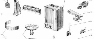
Arrangement of components of a lathe with OSU 16K20T1
Location of the components of the lathe 16K20T1
Location of the components of the lathe 16K20T1
Specification of components of a lathe with OSU 16K20T1
- Base - 16K20T1.011000.000-01
- Bed - 16K20T1.010000.000
- Carriage - 16K20T1.051000.000
- Left support for longitudinal displacement screw - 16K20T1.070000.000
- Spindle head with Gamay bearing - 16K20F.023000.000-01
- Longitudinal movement drive - 16K20T1.481000.000
- Fixed fencing - 16K20T1.264000.000
- Thread cutting sensor drive - 16K20F.163.000-03
- Control cabinet - 16D20.211000.000-01
- Movable fencing - 16K20T1.262000.000
- Rotary tool holder - 16Р20Ф.041.SP
- Screw ball pair of transverse movement - 16K20T1.153000.000
- Control cabinet - 16D20.212000.000-02
- Screw ball pair of longitudinal movement - 16K20T1.154000.000
- Rear headstock - 16K20F.030.SP
- Right longitudinal screw support - 16K20T1.071000.000
- Electrical equipment - 16K20T1.183000.000
- Control cabinet - 16D20.213000.000-02
- Electromechanical tailstock quill drive - 16K20F.032.000
- Feed drive cabinet - 16D20.214000.000
- Centralized lubrication - 16K20F.240.SP
- Motor unit with poly V-belt drive - 16K20F.159.000
- Automatic gearbox (AKS) - 16K2SF.158000.000
- Lubrication control AKC - 16K2SF.400.000
- Power chuck with electromechanical drive - 16K20F.092.000
- Transverse movement drive - 16K20T1.482000.000 Transverse feed gearbox - 16K20T1.153000.000-01
- Distribution of communications on the machine - 16K20T1.115000.000
- Wiring of communications along the carriage - 16K20T1.114000.000
- Control panel - 16K20T1.500000.000
- Manual control unit - 16K20T1.501000.000
- Fixed steady rest - 16K25.101.SP
- Screen device for setting up the tool - 16K20F.321.SP
Location of the main components of the 16B20 screw-cutting lathe
Location of the main components of a 16v20 lathe
Specification of the main components of the 16B20 screw-cutting lathe
- Gearbox - 1V62G.81.000
- Electrical cabinet - 1V62G.83V.000
- Feed box - 16B20P.070.000
- Front headstock - 1V62G.24.01
- Chuck guard - 1V62G.93.01
- Bed - 16В20.12.000, -01; 1V62G.12.000
- Carriage and support - 1В62Г.35.000
- Apron - 16B20P.061.000
- Caliper guard - 16K20.261.000
- Rear headstock - 1V62G.30.000
Specification of the main components of the 16V20A machine with a mechanical drive of the upper (cutting) support (supplied by special order)
- Gearbox - 1V62G.81.000
- Electrical cabinet - 1V62G.83V.000-01
- Feed box - 077.0000.000
- Front headstock - 1V62G.24.01
- Chuck guard - 1V62G.93.01
- Bed - 16В20.12.000, -01; 1V62G.12.000
- Carriage and support - 1В62Г.35.000
- Apron – 067.0000.000
- Caliper guard - 16K20.261.000
- Rear headstock - 1V62G.30.000
16K20T1 Location of lathe controls
Location of controls for lathe 16K20T1
16K20T1 List of lathe controls
- Machine control panel
- Spindle speed range setting handle
- Manual Caliper Movement Generator
- Socket for the handle for transverse movement of the caliper
- Tailstock quill clamp handle
- OSU system control and display panel
- Tailstock clamp handle on bed
- Emergency stop button
- Axis of manual movement of the carriage
- Emergency cam release button
- “Control panel lock” switch
- Cooling switch
- Quill travel pedal (double)
- Switch "Start", "Stop" of spindle and feed
- Bulb
- Chuck control pedal
- Spindle speed shift knob
Location of controls for the 16K20T1 lathe. Remote Control
Control panel for lathe 16K20T1
List of controls for the 16K20T1 lathe. Remote Control
- Button “Lubricate bed guides”
- Spindle Jog button
- Lamp "Presence of voltage"
- Minimum release switch of the input circuit breaker
- Mechanical interlocking of the minimum release switch of the input circuit breaker
- Introductory machine handle
- AKS lubrication control warning light
Kinematic diagram of a lathe with OSU 16K20T1
Kinematic diagram of the lathe 16K20T1
Kinematic diagram of the lathe 16K20T1
On machines of version 16K20T1.01, a spindle head is installed, which has 3 speed ranges that can be switched manually. The main movement drive includes a motor unit with an asynchronous electric motor, an automatic 9-speed gearbox AKS-309-16-51 and a spindle head, connected by wedge or polyclick belt drives.
From the Ml engine, through a poly-V belt drive (with pulleys with a diameter of 105 and 264 mm), rotation is transmitted to shaft I of the spindle headstock, and then through gears 1 and 2 to shaft II. Next, three spindle speed ranges are provided (22.4–315; 63–900; 160–2240 rpm). Within each range, the speed is infinitely adjustable by changing the speed of the ML electric motor
To obtain the first range of rotation frequencies, movement from shaft II (through gears 4 and 3) is transmitted to shaft III, then (through gears 7 and - to shaft IV and further (through gears 9 and 11) - to shaft V (spindle ).
To obtain the second range, wheel 11 is engaged with wheel 6, and wheel 3 is disengaged with wheel 4.
To obtain the third range, wheel 10 is engaged with wheel 5, and wheel 3 (as in the previous case) is disengaged with wheel 4. Gears 12 and 13 are used to rotate the BE-178 thread-cutting sensor.
Gear 12 is split and serves to select a gap in the meshing in order to prevent mismatch between the position of the spindle and the sensor.
An M2 electric motor (adjustable high-torque DC or frequency-controlled asynchronous) is used to drive the support feed along the X-axis (transverse movement). From the M2 motor, rotation (through gears 14 and 15) is transmitted to a ball screw (step P = 5); reverse communication along the path is carried out by a photopulse sensor BE-178.Chain for driving the caliper feeds along the Z axis (longitudinal movement): M3 engine - gears 16, 17 - ball screw (P = 10) - BE-178 sensor.
The rotation chain of the six-position turret: asynchronous electric motor M4 - gears 18 and 19 - worm 20 - worm gear 21. The asynchronous motor M5 rotates the gear pump VG11-11A, which provides centralized lubrication of the machine.
Kinematic diagram of a 16V20 screw-cutting lathe
Kinematic diagram of a 16v20 screw-cutting lathe
Scheme for installing bearings on a 16v20 screw-cutting lathe
Installation diagram of bearings for a 16v20 screw-cutting lathe
List of bearings for a 16v20 screw-cutting lathe
Adjusting the spindle bearings of a 16v20 screw-cutting lathe
Spindle bearings are adjusted at the factory and do not require additional adjustment.
In case of emergency, the consumer can resort to adjusting the spindle supports using highly qualified specialists.
However, before this it is necessary to check the rigidity of the spindle assembly. To do this, a jack with a laboratory-tested dynamometer is installed on the frame under the spindle flange, and a force directed vertically from bottom to top is applied to its flange through a gasket that protects the spindle from damage.
The spindle displacement is controlled by a certified indicator with a division value of no more than 0.001 mm, installed on the spindle head and touching the upper part of the spindle flange with its measuring tip. A spindle deflection of 0.001 mm should occur with an applied force of at least 45-50 kgf. If the load value at a displacement of 0.001 mm is significantly lower than specified, then the bearing must be adjusted.
Spindle bearing set:
- 33. Front bearing No. 4-3182120 - double-row radial roller
- 18. Rear bearing No. 6-8116 - single thrust ball
- 17. Rear bearing No. 6-7216 - tapered angular contact roller bearing, 80x140x26
Description of the main components of a lathe with OSU 16K20T1
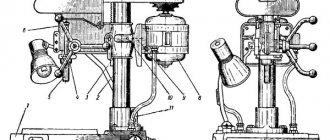
Headstock
The design of the spindle assembly (Fig. 2.6) largely determines the operational performance of the machine, i.e., the cutting modes used and the achieved accuracy and processing performance. Therefore, the headstock body 1 is made in the form of a rigid cast iron and is securely fixed to the frame. The gears are hardened and ground according to the tooth profile. The most important part of the spindle head is the spindle 5, which directly perceives the cutting forces. The front end of the spindle has a flange to which the jaw chuck is attached. The front support is a double-row tapered roller bearing 4, and the rear support is a single-row tapered roller bearing 3. The use of springs 2 in the supports, intended for constant selection of clearances in the bearings, helps to increase the accuracy and rigidity of the spindle assembly. The bearings are adjusted by the machine manufacturer, which ensures their operation without operator intervention (except in cases of repair).
The spindle head provides manual switching of three speed ranges with the ratio: 1.17:1; 1:2; 1:8, which together with a 9-speed gearbox provides 22 spindle speeds in the ranges: 12.5..200; 50-800; 125-2000 rpm (9 speeds in each range) with the main version of the machine with an electric motor of 1460 rpm).
The spindle is mounted in double-row and single-row conical bearings. Bearings are adjusted at the machine manufacturer's factory and do not require adjustment during operation. The spindle head is installed with the spindle axis along the calculated line of the machine centers on the bed using two screws (see Fig. 5).
On the 16K20T1 machine without AKS, a spindle head with two electromagnetic clutches is installed, providing speed switching with a 1:2 ratio when manually setting the speed with two handles that move movable gear blocks. Spindle speeds for different positions of handles or clutches for functions M38, M39, see table.
Drive for longitudinal movement of the caliper
The drive for longitudinal movement of the caliper (Fig. 2.7) includes a ball screw gear (diameter 63 mm, pitch 10 mm), screw supports 2, gearbox 1 (gear ratio 1:1), DC electric motor 6 and feedback sensor 3 connected with screw via coupling 4.
If the machine is equipped with a frequency-controlled asynchronous motor, then a gearbox with a gear ratio of 1:2 is installed, and a feedback sensor is built into the electric motor. The gap in the gear mesh of the gearbox is selected by moving the adapter plate 5 (with the electric motor installed on it) relative to the gearbox housing.
Drive for transverse movement of the caliper
The drive for the transverse movement of the caliper (Fig. 2.8) includes a ball screw gear (diameter 40 mm, pitch 5 mm), screw supports 1, gearbox 2 (gear ratio 1:1), DC electric motor 5 and feedback sensor 4 connected with a screw using an elastic coupling 3. If the machine is equipped with a frequency-controlled asynchronous motor, then a feedback sensor is built into the electric motor. The gap in the gearing is selected by the vertical displacement of plate 6 (with an electric motor installed on it).
Six position turret
A six-position turret (Fig. 2.9) with a horizontal axis of rotation is installed on a transverse slide. Six cutter inserts or three tool blocks are mounted in the tool head.
The tool removable head is mounted on the output shaft 5 and is rigidly connected to the movable element 6 of the flat-toothed coupling. The turret head is rotated as follows: from the electric motor 2 (via a worm gear), rotation is transmitted to the shaft 7 of the cam coupling half 8, which is rigidly connected to the shaft 5. At the initial moment of rotation, the elements 3 and 6 of the flat-gear coupling are disengaged and the head rotates to the desired position, which is controlled by an electric sensor 10. Then the electric motor is reversed, the shaft 7 of the cam clutch rotates in the opposite direction, and the movable element 6 of the flat-toothed coupling (with the tool head) is kept from rotating by a lock, as a result of which element 6 is fixed on the teeth of the fixed element 3 of the flat-toothed coupling. The clamping signal from the limit switch 9 is supplied to the control panel, and the rotation motor is turned off and the processing cycle begins. For manual rotation and clamping of the turret head (when setting up the machine), a hexagonal wrench is provided on shaft 1. The cutting tool should be positioned as evenly as possible on the tool head to avoid imbalance when the head rotates.
Tailstock
The tailstock (Fig. 2.10) is mounted on the frame using handle 3, eccentric shaft 5, bar 8 and a lever system. The force of pressing the tailstock to the frame is adjusted with screws 7 and 2 (with lock nuts 6 and 1 released), changing the position of the clamping bar 8. The quill is moved manually (using a flywheel) or using an electromechanical drive 4.
Cartridge
The machine is equipped with a three-jaw chuck (Fig. 2.11) with an electromechanical drive for clamping the workpiece.
The cams 3 of the cartridge move in the radial direction as a result of the translational movement of the wedge 4 associated with the rod 5, which is connected to the rod 7 through a package of disc springs 6. The latter is connected by a screw-rod 8 to the electromechanical head 1, which is a special asynchronous electric motor, in the armature of which nut is built in. When the armature rotates, the screw-rod 8 moves in the longitudinal direction, driving the rod 7. The greater the amount of movement of this rod, the greater the compression force of the spring package and, consequently, the clamping force of the cartridge. This force can be adjusted by moving the proximity switches 2.
Machine lubrication 16k20t1
The machine uses an automatic spindle head lubrication system. The gear pump draws oil from the reservoir and delivers it through a strainer to the spindle bearings and gears. About a minute after the main electric motor is turned on, the oil indicator disk begins to rotate. Its constant rotation indicates normal operation of the lubrication system. The oil from the spindle head is drained into the reservoir through a mesh filter and a magnetic cartridge. During operation, it is necessary to monitor the rotation of the oil indicator disk; When it stops, you must turn off the machine and clean the filter by rinsing its elements in kerosene. The filter is cleaned as it becomes clogged, but at least once a month.
Every day before starting work, check the oil level at the oil indicator and, if necessary, add oil.
Lubrication of the carriage and bed guides is also carried out automatically from the C48-12 station installed on the base of the machine. When the pump is turned on, oil is supplied under pressure (via a hose) to the junction box on the carriage. The pump is turned on simultaneously with the machine turning on, and subsequently upon command from the time relay (with an interval of 10..240 minutes). When the pump is running, the warning light comes on. If necessary, you can add additional oil by pressing the “Lubricant Push” button.
The supports of the caliper feed screw pairs and the ball nut are lubricated manually (through an oiler) with plastic lubricant.
Proper and regular lubrication of the machine is essential for its normal operation.
Operating procedure of the machine
Before starting work, turn on the machine and check the position and reliability of fastening of the emergency travel limit cams on the longitudinal and transverse rulers, as well as the position and reliability of fastening of the tailstock on the frame (if used). When processing in a chuck, the tailstock is moved to the extreme right position. Using special handles, the ease of movement of the caliper in the longitudinal and transverse directions is checked. In the “Manual Control” mode, the operation of the machine mechanisms is checked: switching rotation speed ranges; movement of the caliper in the longitudinal and transverse directions at high speed and working feeds; operation of emergency and interlocking electrical switches; lubricant supply; spindle rotation, etc.
After checking the operation of the machine in manual mode and making sure that it is correct, turn on the automatic cycle - bypassing the circuit at idle (without installing the workpiece).
During normal operation of the machine, the first part is processed according to the NC, it is measured, and the CP is corrected using the CNC.
Electrical equipment of a screw-cutting lathe 16B20
Electrical diagram of a 16B20 screw-cutting lathe
Electrical diagram of a 16v20 screw-cutting lathe
- Electrical cabinet, model 1V62G.83V.000
- Supply network: voltage - 380 V, current - three-phase, frequency - 50 Hz
- Control circuit: voltage - 110 V, current - alternating
- Local lighting circuit: voltage - 24 V, current - alternating
- Signaling circuit: voltage - 22 V, current - alternating
- Rated current (sum of rated currents of simultaneously operating electric motors) - 17.6 A
The electrical equipment of the machine is designed to connect power units, lighting and signaling devices to a three-phase alternating current network with a solidly grounded neutral wire, as well as to ensure their protection from overloads, short circuit currents and other factors. All relay contact and other electrical equipment used is simple in design and has proven itself well when working on machine tools. This ensures reliable operation of electrical equipment and the possibility of its maintenance by semi-skilled specialists.
Electrical equipment, with the exception of a few devices, is mounted in electrical cabinet 2 (Figure 8), located on the rear side of the headstock housing.
The power circuit of the machine includes three three-phase asynchronous electric motors, safety devices and switches.
The control circuit includes relay contact and other devices located in the cabinet, as well as a push-button station 11 SB1.1 SB1.2 (Figure 9) for starting and stopping the main drive, limit switches 19 SQ1 for controlling the accelerated motor and limit switches SQ2, SQ3 locking the chuck guard and gearbox cover.
The local lighting circuit EL1 ensures the operation of a machine lamp with a flexible stand and a built-in switch. Illumination 1500 lux.
The signaling circuit includes signal lamps 29 (HL1) and 31 (HL2).
Description of the operation of the electrical circuit
Turning on the input switch QF1 (Figure 12) when there is voltage in the network is accompanied by the lighting of the HL1 lamp.
The start of the electric motor of the main drive M1 is carried out when the input switch QF1 is turned on by pressing the button SB1.1 of the push-button station, which closes the coil circuit of the magnetic starter KM1. In this case, the magnetic system of the starter is triggered and closes its normally open main and auxiliary contacts KM1, that is: the magnetic starter KM1 will switch to self-power, because one of its auxiliary contacts will close the coil power circuit parallel to the SB1.1 button and when the latter is released the circuit will not break; the electric motor of the main drive M1, powered by the power circuit through the closed main contacts of the KM1 starter, will turn on;
The electric motor of the main drive M1 is stopped by pressing the button of the push-button station SB1.2. In this case, the coil circuit of the magnetic starter KM1 will open, it will be de-energized, all contacts of the starter will open, i.e. the electric motor M1 will turn off, the self-supply circuit of the magnetic starter will break.
The rapid movement motor M3 is started by pressing the jog button built into the apron handle and acting on the limit switch SQ1. The normally open contact of the limit switch, when the button is pressed, closes the power circuit of the electromagnet coil of the KM2 starter, which in turn closes the KM2 contacts of the power circuit of the high-speed motor. Switch QF2 is always on.
When the jog button SQ1 is released, the control circuit will open and the starter coil will be de-energized, i.e. the KM2 contacts will open and the M3 electric motor will turn off. Starting and stopping the electric pump M2 is carried out using switch SA1 installed on the front panel of the electrical cabinet.
Technical characteristics of the machine 16K20T1
| Parameter name | 16K20T1 | 16K20T1.01 | 16K20T1.02 |
| Basic machine parameters | |||
| CNC system type | NTs-31 | NTs-31 | NTs-31 |
| The largest diameter of the workpiece above the bed, mm | 500 | 500 | 500 |
| The largest diameter of the workpiece above the support, mm | 215 | 215 | 220 |
| Maximum length of the workpiece, mm | 1000 | 1000 | 1000 |
| Maximum processing length, mm | 900 | 900 | 905 |
| The largest diameter of the processed rod, mm | 53 | 53 | 53 |
| Spindle | |||
| Main movement motor power, kW | 11 | 11 | 11 |
| Number of spindle speeds | 24 | 22 | b/s |
| Spindle hole diameter, mm | 55 | 55 | 55 |
| Spindle speed limits, rpm | 10,0…2000 | 12,5…2000 | 22,4…2240 |
| Number of automatically switched speeds | 2 | 9 | b/s |
| Spindle speed range, manually set, rpm | Row I - 10..1000 Row II - 20..2000 | Row I - 12.5..200 Row II - 50..800 Row III - 125..2000 | Row I - 22.4..355 Row II - 63..900 Row III - 160..2240 |
| Headstock spindle center according to GOST 13214-67 | 7032 - 0043 Morse No. 6 | 7032 - 0043 Morse No. 6 | 7032 - 0043 Morse No. 6 |
| Tailstock quill center according to GOST 13214-67 | 7032 - 0045 Morse No. 5 | 7032 - 0045 Morse No. 5 | 7032 - 0045 Morse No. 5 |
| Spindle end according to GOST 12593-72 | 6K | 6K | 6K |
| Maximum torque on the spindle, Nm | 1000 | 1000 | 1000 |
| Maximum drilling diameter for steel/cast iron, mm | 25/ 28 | 25/ 28 | 25/ 28 |
| Submissions | |||
| Maximum movement of the caliper longitudinal / transverse, mm | 900/ 250 | 900/ 250 | 905/ 275 |
| Maximum speed of longitudinal/transverse working feed, m/min | 2,0/ 1,0 | 2,0/ 1,0 | 2,0/ 1,0 |
| Limits of pitches of cut threads, mm | 0,01..40,959 | 0,01..40,959 | |
| Range of longitudinal feed speeds, mm/min | 0,01..2,8 | 0,01..2,8 | 0,01..20,47 |
| Transverse feed speed range, mm/min | 0,005..1,4 | 0,005..1,4 | 0,005..10,23 |
| Speed of fast longitudinal/transverse strokes, m/min | 6/ 5 | 6/ 5 | 7,5/ 5 |
| Discretion of longitudinal/transverse movement | 0,01/ 0,005 | 0,01/ 0,005 | 0,01/ 0,005 |
| Number of positions on the rotary toolholder (number of tools in the turret) | 6 | 6 | 6 |
| OSU system parameters | |||
| OSU system designation | NTs-31 | NTs-31 | NTs-31 |
| Number of coordinates | 2 | 2 | 2 |
| Number of simultaneously controlled coordinates | 2 | 2 | 2 |
| Resolution in the longitudinal direction (discreteness of the task along the Z axis), mm | 0,01 | 0,01 | 0,01 |
| Resolution in the transverse direction (discreteness of the task along the X axis), mm | 0,005 | 0,005 | |
| Feedback sensor type | BE-178 | BE-178 | BE-178 |
| Threading sensor type | BE-178 | BE-178 | BE-178 |
| Electrical equipment. Drive unit | |||
| Number of electric motors on the machine | 5 | 6 | 7 |
| Main motion drive electric motor, kW | 11 | 11 | 11 |
| Electric motor for longitudinal feed drive, kW | 2,2 | 2,2 | 2,2 |
| Cross feed drive electric motor, kW | 1,1 | 1,1 | 1,1 |
| Turret head electric motor, kW | — | 0,18 | 0,37 |
| Electric motor of the carriage lubrication station, kW | 0,12 | 0,12 | 0,18 |
| Electric motor of the spindle head lubrication station, kW | — | — | 0,27 |
| Cooling pump electric motor, kW | 0,12 | 0,12 | 0,18 |
| Total power of electric motors, kW | 14,54 | 14,72 | 16 |
| Total power of the machine, kW | 24 | 24 | 25 |
| Dimensions and weight of the machine | 3175 x 1700 x 1700 | 3175 x 1700 x 1700 | 3230 x 1700 x 1700 |
| Weight of CNC machine, kg | 3800 | 4100 | 3800 |
Information about the manufacturer of the screw-cutting lathe 16B20
The manufacturer of the 16B20 screw-cutting lathe is the Astrakhan Machine Tool Plant , founded in 1944.
The main activity of the Astrakhan Machine Tool Plant is the production of metal-cutting, press-forging, abrasive-cutting, and woodworking equipment. In addition, the plant produces components for machine tools and equipment.
The plant produces screw-cutting lathes models 1V62G , 16V20 , 1V625 , 1V625M with a distance between centers of 750, 1000 and 1500 mm and a CNC lathe AS16M20F3 .
Machine tools produced by the Astrakhan Machine Tool Plant, ASZ
- 1A62G
- universal screw-cutting lathe Ø 400 - 1V62G
- universal screw-cutting lathe Ø 445 - 1В625м
– universal screw-cutting lathe Ø 500 - 16B20
– universal screw-cutting lathe Ø 445 - AS2116m
- tabletop drilling machine Ø 16 x 100 - SMZh-172
- machine for cutting reinforcing steel Ø 24