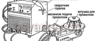
Types of transformer welding
Today there are different types of welding transformers, which differ in design and operating principle. The most popular on the market among them, which you can make yourself, is considered to be a welding transformer for arc and resistance welding.
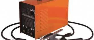
Arc Welding Transformer
Transformers for arc welding are widely used among home craftsmen. There are several reasons for this:
- reliable and fairly simple design of the tool;
- mobility;
- quite wide operating range;
- Ease of Management;
- good performance.
Of course, in addition to numerous advantages, DC manual arc welding also has a number of disadvantages:
- low efficiency rate;
- The quality of the weld depends entirely on the level of professionalism of the welder himself.
A transformer for manual welding is usually used in the process of carrying out various construction or repair work, producing metal structures, joining individual metal samples, as well as connecting pipeline communications. Using manual arc welding, you can cut metal and weld it, with different thicknesses.
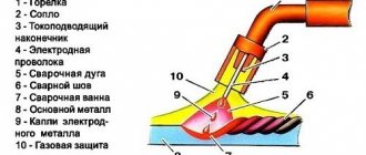
These types of instruments have a fairly simple design. The welding unit includes:
- the transformer itself;
- electrode holder;
- current regulator;
- mass clamp.
It is necessary to highlight the main element of the device - the transformer, which can have a different design. The most popular today are homemade instruments equipped with a magnetic core of a U-shaped, toroidal configuration.
Two windings of aluminum or copper wire are placed around the magnetic core. The thickness of the wire on the windings depends on the operating characteristics of the unit and the number of turns made.
Spot Welding Transformer
This type of welding is also called resistance welding. The TS transformer has characteristic differences from a tool designed for arc welding. The key one is the technology of welding metal samples. For example, melting by arc welding is carried out by an electric arc, which is formed between the electrode and the product being welded, while in the case of resistance welding, the welded area is spot heated with electricity (for which two sharpened copper electrodes are used), the parts are connected under the influence of high pressure (such Thus, the metal of the welded samples melts at the connection point, after which it merges into one whole).
Spot welding is widely used in the automotive industry, the construction industry, for joining thin aluminum sheets, copper samples, stainless steel, for welding strands, creating reinforced concrete frames from reinforcement, and other metals for which special conditions must be created for joining.
Design
Every home craftsman tries to provide himself with a wide variety of tools, especially a welding unit, which is simply an indispensable assistant in business activities. This does not rule out the possibility of assembling such a device yourself. The design of a welding transformer made at home can be very diverse. Such a device can be used for arc and spot welding of different types of metal products.
Car enthusiasts can use a TD 500 transformer to build a spotter that will allow them to repair a car body at any time.
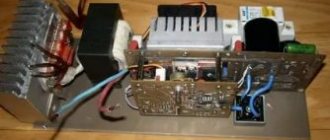
All welding devices made on the basis of a standard transformer have the same operating principle; they differ only in design characteristics. The semi-automatic welding machine has such a simple design that it can even be made from an ordinary microwave oven. Such a tool is capable of operating when using alternating or direct currents, and the quality characteristics of the seam will not be affected.
The circuit diagram of a semi-automatic welding machine includes several mandatory parts that are definitely present in the household of any household craftsman.
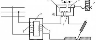
Operating principle of a welding transformer
So, it’s time to take a closer look at what a welding transformer is and how it functions. The equipment operation algorithm includes several main stages:
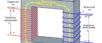
- From the power supply network, current is supplied to the primary winding. As a result, a magnetic flux is generated that closes on the core of the device;
- Next, the voltage is supplied to the secondary winding.
- A core made of ferromagnetic materials, on which both windings are located - primary and secondary, generates a magnetic field.
- The number of turns of the coil, or rather their difference, changes the voltage and current. The transformer is calculated based on these parameters.
There is a direct relationship between the number of turns of the secondary winding and the output voltage. If you need to increase the output voltage, then you should add the number of turns of the secondary coil, and vice versa. The welding transformer is a step-down device. For this reason, the number of turns on the secondary winding is less than on the primary.
In addition, the device and components of the welding machine allow you to regulate the current strength. To do this, it is necessary to change the distance between the secondary and primary windings. An inverse relationship is observed here: the shorter the distance, the stronger the current, and vice versa - the greater the distance, the smaller the value. These adjustments enable the welder to work with materials that differ in both composition and thickness.
Types of welding machines
There are several main types:
Welding transformer. A step-down transformer is used for the converter.
Welding transformer
Welding inverter. An inverter power supply with PWM serves as a converter here.
Welding rectifier. This is the same as a welding transformer, only it has a diode or thyristor rectifier in the secondary circuit.
Welding rectifier
Semi-automatic Welding is carried out in an inert environment; a gas cylinder is used for this.
Also read: Is it possible to connect copper and aluminum wires?
Transformer circuit
When making a transformer (spotter) yourself, you must make a calculation. What parts does the welding transformer circuit include? Any tool of this type includes a copper wire wound on a core. The number of copper wires for the main apparatus does not matter; it can even be made from a microwave oven.
The overall transformer circuit must include a diode bridge. When the unit is intended for spot welding, the diagram is a little more complicated. Here, in addition to the copper wire and diode bridge, the presence of capacitors, thyristors, and diodes is required. These additional elements will allow you to adjust the current as accurately as possible, plus the quality of the seam will be much better.
The transformer for spot welding has a complex circuit and design. Of course, everyone decides for themselves which welding tool is more suitable at home. The main thing is to know exactly its functional responsibilities.
What is the calculation of a welding transformer based on?
The main provisions on which the calculation of a transformer for a semi-automatic welding machine is based are those on which the principle of its operation is based. The main element of the system is a step-down transformer. This element allows you to change the standard mains voltage of 220 V to a lower one, which requires an idle welding transformer of 60 V. The current can be adjusted based on the current-voltage characteristics of the system itself. The average current characteristics for a 3 mm electrode is 120 A. It is in this case that the calculation of the welding machine turns out to be important, because when the rod begins to melt at a certain current value, it also heats the winding wire and the transformer core at certain values. Thus, to calculate the optimal power of a transformer, you should find out the operating value, which can be determined by the operating current. To do this, use the formula U2 = 20+0.04*I2. Here:
- U2 – voltage available on the secondary winding;
- I2 is the maximum welding current that the machine can produce.
Welding rectifier - features of operation and assembly
To perform certain types of welding work, for example, with stainless steel, the use of alternating current supplied by a transformer is not used. To work with such metals, a constant voltage supply is required. In addition, direct current cutting reduces the consumption of electrodes, and metal spattering is prevented during welding.
To perform work in such conditions, welding rectifiers are used, which allow welding with direct and reverse polarity current. If you have experience in installing electronic circuits, then you can also assemble such a device yourself.
The basis of the welding rectifier will be the same step-down transformer. The difference lies in the presence of a rectifying electronic circuit. If desired, you can remake the already described welding transformer or assemble a universal device that will allow you to weld with both alternating and direct current.
The simplest diagram of the electronic part of a welding rectifier looks like this:
Schematic diagram of a welding rectifier
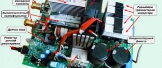
When assembling such devices, the following design features should be taken into account:
- The main part of the device is a rectifier bridge made of powerful power diodes. They are connected according to the diagram, taking into account polarity.
- Smoothing of current ripple is carried out due to a filter made on the capacitor and choke coil. Please note that the components must have a margin of 2.5 - 3 permissible voltage.
- When working with high currents, the elements heat up. Semiconductor diodes are sensitive to overheating. Therefore, they are installed on radiators, which will increase the intensity of heat removal.
- When enclosing the device in a housing, it becomes mandatory to use a fan to increase cooling efficiency.
We pay attention to the connection of individual elements of the circuit. Considering that they will be exposed to high current, it is necessary to ensure reliable contact. If this is not done, then the wires in these areas will heat up and burn out. The preferred option is with fastening using platforms with a bolt and nut.
The choke in such designs is made in the form of a separate remote inductor, which is connected as needed. Note that installing a rectifier does not prevent the welding current from changing using the secondary winding coil position regulator.
As you can see, there are no difficulties in assembling a welding machine yourself. But it’s worth working on such devices only if you have experience in designing simple devices that operate with lower currents. Otherwise, entrust the assembly to a specialist or buy a factory welding machine.
Microwave welding machine:
Transformer calculation
How is a welding transformer calculated?
As mentioned earlier, AC welding transformers include two windings, a core, which are responsible for the key technical characteristics of the tool. Assuming in advance the winding voltage, current strength, and other additional parameters, calculations are made of the core, windings, and copper wire cross-section.
When making calculations, the basis is the following parameters:
- U1 is the voltage of the primary winding, which is the mains voltage, from which the welding will work (220V/380V).
- U2 – voltage of the secondary winding (no more than 80V). The voltage of electricity created after a step down. It is necessary to excite the welding arc;
- I – current strength of the secondary winding (calculated depending on the electrodes intended for the work and the thickness of the metal being welded).
- Sc – cross-sectional area of the core (taken in the range of 45-55 cm²). This parameter affects the quality and reliability of the tool.
- So – core window area (taken in the range of 80-110 cm²). The parameter is taken from the calculation of excess heat removal, high-quality magnetic dissipation, and the convenience of winding copper wire.
- RT – winding current density (2.5-3A/mm2 – for homemade transformers). a rather significant parameter that is responsible for electrical losses on the windings of the tool.
Do-it-yourself transformer for contact welding of wires, including copper ones – Welding
page » Welding equipment » How to make a welding transformer with your own hands. How to calculate winding. Homemade arc or resistance welding machine
If you have the necessary plumbing and electrical installation tools (we will talk about them in detail below), and you have the appropriate professional skills, then you will be able to make a welding transformer with your own hands.
You will, of course, have expenses, but they will be incomparably lower compared to the costs of purchasing a factory-made gadget. But how much pleasure you will get in the process of your favorite homemade work. And the delight at the moment of successful start of electric welding is, in general, incomparable!
In this article we will give you a lot of useful advice on choosing, calculating and manufacturing a welding transformer (hereinafter referred to as ST), which will help you optimize costs and save your budget.
A properly made device with your own hands is no worse than a factory one.
Appearance of a homemade welding transformer. East. https://autokuz.ru/kuzovnoy-remont/kak-sdelat-svarochnyj-apparat-svoimi-rukami.html.
The article will talk about two types of welding transformers. For welding:
The range of tools and equipment for the manufacture and assembly of both types of ST is identical. We will need the following:
- electrical voltage indicator . To control the absence of the latter on electrical contacts, and thereby ensure safety when performing electrical installation work;
- Angle grinder (aka “grinder”, “whip-machine”, etc.) with a set of discs (cutting, grinding, etc.);
- electric drill with a set of metal drills and a core;
- AC tester or voltmeter
- any " scriber ". Used for marking on metal;
- metalwork clamps . For fixing parts when marking “in place”;
- set of power tools . The specific composition of the kit depends on the materials that will be used in the manufacture of the ST. In general, it is like this: a complete electric soldering iron. We will perform soldering using POS-40 solder;
- screwdrivers (various sizes with straight and Phillips slots);
- wrenches: wrenches;
- caps;
- end;
It is more convenient to carry out all work on a bench with an electrical insulating coating, equipped with a bench vice.
To manufacture a transformer, components and materials are required that differ depending on the type of transformer. In general, the following is required:
- protective casing . Must provide: protection from electric shock;
- exclude the possibility of any objects getting inside the gadget;
Important : PVC insulating tape cannot be used, because it is destroyed when heated.
Homemade welding transformer for arc welding
Before you begin further work on the manufacture of CT, you should decide what exactly you will create. You need:
- choose the design and electrical circuit diagram of the future device;
- carry out electrical and, if necessary, structural calculations of its parameters.
Only after this should you select the necessary equipment, materials and prepare, if necessary, special tools.
How to calculate a welding transformer. Scheme
The question of how to calculate a homemade welding transformer is very specific, since it does not correspond to standard diagrams and generally accepted rules. The fact is that when making homemade products, the parameters of their components are “adjusted” to the components already available (mainly to the magnetic circuit). Moreover, it often happens that:
- transformers are not assembled from the best transformer iron;
- the windings are wound with not the most suitable wire and many other negative factors.
As a result, homemade products heat up and “hum” (the core plates vibrate at the frequency of the mains: 50 Hz), but at the same time they “do their job” - weld metal.
Based on the shape of the cores, transformers are classified into the following main types:
Types of core. East. https://v277.ru/svarka/65-svarochnyj-transformator.
Explanations for the picture:
- a – armored;
- b – rod.
Rod- transformers , compared to armor- type transformers, allow higher current densities in the windings. Thanks to this, they have a higher efficiency, but the labor intensity of their production is much higher. However, they are used more often.
https://www.youtube.com/watch?v=kRjG12vSQo0
On the rod core, the winding circuits shown in the figure are used.
Explanations for the picture:
- a – network winding on both sides of the core;
- b – the corresponding secondary (welding) winding, connected in counter-parallel;
- c – network winding on one side of the core;
- d – the corresponding secondary winding, connected in series.
For example, let’s calculate the ST assembled according to the scheme “c” - “d”. Its secondary winding consists of two equal parts (halves). They are located on opposite shoulders of the magnetic circuit, and are connected in series to each other. Calculations consist of determining the theoretical and selecting the actual dimensions of the magnetic circuit.
We determine the CT power (based on the current in the secondary winding) from the following considerations. For electric welding in everyday life, coated electrodes Ø, mm: 2, 3, 4 are most often used. We choose the “golden mean” for the most popular ones - 120...130 A. CT power is determined by the formula:
P = Uх.х. × Ist. × cos(φ) / η, where:
- Uх.х. — open circuit voltage;
- Ist. — welding current;
- φ is the phase angle between voltage and current. We accept: cos(φ) = 0.8;
- η - efficiency. For homemade ST: efficiency = 0.7.
If you calculate the magnetic core according to the reference book, then its cross-section for the selected current is 28 sq.cm. In practice, the cross-section of the magnetic circuit for the same power can vary within the range: 25...60 sq.cm.
For each section, it is necessary to determine (using a reference book) the number of turns of the primary winding to ensure the specified output power. We will only note that the larger the cross-sectional area of the magnetic circuit (S), the fewer turns of both coils will be needed. This is an important point, since a large number of turns may not fit into the “window” of the magnetic circuit.
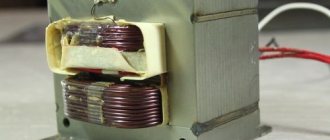
It is possible to use the magnetic circuit of an old transformer (for example, from a microwave oven, of course, after some reconstruction of it - replacing the secondary winding).
Old transformer. East. https://strgid.ru/mozhno-li-sdelat-svarochnyi-apparat-svoimi-rukami-chto-nuzhno-dlya-togo-chtoby-pravilno-sobrat-svaro.
If you do not have an old transformer, then you should purchase transformer iron from which you will make the CT core.
Iron for magnetic circuit. East. https://strgid.ru/mozhno-li-sdelat-svarochnyi-apparat-svoimi-rukami-chto-nuzhno-dlya-togo-chtoby-pravilno-sobrat-svaro.
Explanations for the picture:
- a – L-shaped plates;
- b – U-shaped plates;
- c – plates made of transformer steel strips;
- c and d – dimensions of the “window”, cm;
- S = a x b – cross-sectional area of the core (yoke), sq. cm.
If you correctly calculate the magnetic circuit, the CT windings will not heat up, and the welder itself will work reliably.
Calculation of the number of turns of the primary windings at a supply voltage of 220...240 V, welding currents selected by us and magnetic circuit parameters can be made using the following formulas: N1 = 7440 × U1/(Siz × I2). For windings on one arm (half of the winding on top of each other, connected in series);
N1 = 4960 × U1/(Sfrom × I2). The windings are spaced on different arms.
Conventions in both formulas:
- U1 – power supply voltage;
- N1 - number of turns of the primary winding;
- Siz is the cross-section of the magnetic circuit (sq. cm);
- I2 is the specified welding current of the secondary winding (A).
The output voltage of the secondary winding of the CT in the no-load mode of homemade welding transformers is, as a rule, within the range of 45...50V. Using the following formula, you can determine its number of turns: U1/U2 = N1/N2.
For the convenience of selecting the strength of the welding current, taps are made on the windings.
Winding the welding transformer and installation
For the primary winding of the transformer, a special heat-resistant copper wire with cotton or fiberglass insulation is used.
Attention : we strongly do not recommend using rubber-insulated wires for winding a welding transformer.
Taking into account the power selected above, the electric current in the primary winding can reach 25 A. Based on these considerations, the primary winding of the CT should be wound with a wire having a cross-section of ≥ 5...6 sq. mm. This, among other things, will significantly increase the reliability of the ST.
The secondary winding is made of copper wire, the cross-section of which is: 30...35 sq. mm. Particular attention should be paid to the choice of insulation of the secondary winding wire, since a large welding current flows through it. It must be very reliable - special attention should be paid to heat resistance.
When installing the windings, pay attention to the following:
- winding is carried out in one direction;
- An insulating layer of additional insulation is laid between the rows of windings (we recommend cotton).
The assembled CT should be placed in a protective casing with holes for ventilation.
See how the task of assembling the device was implemented:
Do-it-yourself resistance welding from a welding transformer
Contact welding creates a welded connection between parts due to the following simultaneous effects on them:
- heating the area of their contact with an electric current passing through it;
- a compressive force is applied to the joint area.
There are three types of resistance welding:
- point;
- butt;
- suture
We will tell you about a homemade CT for the most popular: resistance spot welding (the other two require very complex equipment).
Spot resistance welding. East. https://moyasvarka.ru/process/kak-sdelat-kontaktnuyu-svarku-svoimi-rukami.html.
Explanations for the figure: 1 – electrodes supplying welding current to the products being welded; 2 – welded products with an overlap connection;
Simple calculation of a transformer for welding
Standard methods for calculating transformers are unacceptable in most cases, since iron of non-standard shapes and wire with an unknown cross-section calculated approximately are used. During the calculation, such characteristics of the welding transformer as the cross-sectional area of the magnetic core and the number of turns were obtained. It is worth noting that when the cross-sectional area is doubled, the characteristics of the transformer itself will not deteriorate. You only have to change the number of turns of the primary winding to achieve the required power.
The larger the cross-section of the magnetic circuit, the fewer turns will have to be wound. Use this quality if you have difficulty with the winding wire. To calculate the number of turns of the primary winding, you can use simple formulas:
Dependence of the current in the primary winding of the transformer on the supply voltage, in no-load mode.
- N1 = 7440×U1/(Siz×I2);
- N1 = 4960×U1/(Siz×I2).
The first is used when calculating welding machines in which both windings are located on the same arm. For spaced windings, the second formula should be applied. In these formulas, Siz is the cross section of the magnetic core, measured before carrying out the calculations. Please note that when the windings are separated into different arms, you will not receive a current of more than 140 A at the output of the welding machine. And for any type of device, it is also impossible to take into account a current value that is more than 200 A. And don't forget that you have many unknowns:
- type of transformer iron;
- network voltage and its changes;
- resistance in the power line.
To exclude the possibility of influence of such minor factors on the operation of the welding transformer, it is necessary to make a tap every 40 turns. You can change the operating mode of the transformer at any time by applying the supply voltage to a smaller or larger number of turns.
Source
Do-it-yourself semi-automatic welding machine 30A – 160A
Technical data of our semi-automatic welding machine:
Supply voltage: 220 V Power consumption: no more than 3 kVA Operating mode: intermittent Operating voltage regulation: stepwise from 19 V to 26 V Welding wire feed speed: 0-7 m/min Wire diameter: 0.8 mm Welding current: PV 40% - 160 A, PV 100% - 80 A Welding current control limit: 30 A - 160 A
A total of six such devices have been made since 2003. The device shown in the photo below has been in service since 2003 in a car service center and has never been repaired.
Transformer calculation: online calculator or old-fashioned method for home - choose yourself
Repair of modern electrical appliances and the manufacture of home-made structures are often associated with power supplies, chargers and other devices that use transformer energy conversion. Their condition must be analyzed and assessed.
I believe that an online calculator that works according to a prepared algorithm, or the old proven old-fashioned method with formulas that requires a thoughtful attitude, will help you calculate the transformer. Try both methods, use the best one.
- How to use an online calculator to calculate a transformer step by step Preparation of initial data in 6 simple steps
- Performing online transformer calculations
- How does the power of a dry-type transformer affect the shape and cross-section of the magnetic circuit?
- Features of calculating the transformation ratio and currents inside the windings
- How to calculate the diameters of copper wire for each winding
- Determining the number of turns of windings according to the characteristics of electrical steel: important points
- Taking into account the free space inside the magnetic circuit window
How to use an online calculator to calculate a transformer step by step
Preparing source data in 6 simple steps
Step #1. Specifying the core shape and cross-section
Cores made from W-shaped plates have the best distribution of magnetic flux. The ring shape of U-shaped components has great resistance.
To carry out the calculation, you need to indicate the shape of the core according to the type of plate (by clicking on the point) and its measured linear dimensions:
- The width of the plate under the coil with winding.
- Thickness of the assembled package.
Paste this data into the appropriate table cells.
Step #2. Voltage selection
The transformer is created as a step-up, step-down (which is in principle reversible) or separating structure. In any case, you need to indicate what voltages you need on its primary and secondary windings in volts.
Fill in the indicated cells.
Step #3. AC signal frequency
By default, the standard household network value is set to 50 hertz. If necessary, it must be changed to that required by another calculation. But, this technique is not intended for high-frequency transformers used in switching power supplies.
They are created from other core materials and calculated in different ways.
Step #4. Efficiency
For conventional models of dry-type transformers, the efficiency depends on the applied electrical power and is calculated as an average value.
But, you can adjust its value manually.
Step #5. Magnetic inductance
The parameter determines the dependence of the magnetic flux on the geometric dimensions and shape of the conductor through which the current flows.
By default, the average parameter of 1.3 Tesla is adopted for calculating transformers. It can be adjusted.
Step #6. Current Density
The term is used to select the winding wire according to operating conditions. The average value for copper is 3.5 amperes per square millimeter of cross-section.
To operate the transformer in conditions of increased heating, it should be reduced. For forced cooling or reduced loads, it is permissible to increase. However, 3.5 A/mm kV is quite suitable for household devices.
Performing online transformer calculations
After filling in the cells with the original data, click on the “Calculate” button. The program automatically processes the entered data and displays the calculation results in a table.
AC transformer
A homemade AC welding transformer is a classic type of transformer that is used in the design of a transformer welding machine. A transformer operating on a “permanent” basis is simpler than a transformer on a “permanent” basis, cheaper and more repairable. But it has a number of significant disadvantages. On devices with an alternating current transformer, the arc is less likely to ignite. It burns unstable and requires experience from the welder. Otherwise, the seams will be of poor quality and defective.
However, the variable transformer is the basis of the permanent transformer (which we'll cover later), so you'll still have to learn how to assemble it. And there is nothing complicated about it.
Selection of wires for winding
To assemble an AC welding transformer, you need wires to wind the primary and secondary windings. You also need to make a so-called core. To do this, you need special electrical steel in order to wind the windings on this core.
Let's determine the technical characteristics that our transformer must provide. As an example, we will take a voltage of 60 V and a maximum welding voltage of 120 to 160 Amperes. In this situation, the minimum cross-section of the wires is 4 sq. mm.
But we recommend using wires with a cross-section of 7 sq. mm, this is the best option. When using such wires, your homemade transformer will not be afraid of voltage surges. Well, as for the diameter of the copper core for the primary winding, in this case the best option would be a value of 3 mm.
When selecting wires, pay attention to their sheath. It must be fabric. In no case is it polymer. Because polymers melt easily from excess heat, which often leads to short circuits. If for some reason you were unable to find a wire of sufficient diameter, you can take two thin wires and wind them together.
But keep in mind that in such a situation the winding will increase in size and the transformer will need a larger housing. The dimensions of the device and its weight will also increase. All this information applies to the primary winding. Thicker wires can be used for the secondary winding. Like those with which the electrode holder is connected.
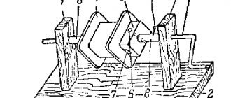
Core Assembly
So, the wires are selected and prepared. Now we need to assemble that same core. The image below shows an ideal core for a homemade transformer in all respects. It is rod type.
For assembly you will need plates made of electrical steel. The optimal thickness of one plate is no less than 0.35 and no more than 0.55 mm. And the required core size (a, b, c, d in the figure above) is calculated separately based on the cross-section of the wire. But many craftsmen choose sizes “by eye”. The main thing is that all the turns fit.
Now let's start assembling the core. Take the plates (they should be L-shaped) and fold them in the order shown in the image below. When you have a core of sufficient thickness, fasten all the plates at the corners with bolts. Process the records using a needle file. Then insulate the core.
Winding
The next stage is winding the transformer. First, the primary winding is wound. It is necessary to make about 210-215 turns. You need to wind it as shown in the image below. When you have made all the turns, attach a textolite plate on top. The ends of the winding can be secured to it using bolts.
Next you need to rewind the secondary winding. It is necessary to make about 70 turns on it. Then attach the textolite plate in the same way and secure the ends of the winding to it using bolts. Ready! The transformer can be used in this form, or can be used for further modifications. The image below shows the final view of the wound transformer.
How to calculate a power transformer using formulas in 5 steps
I present a simplified method that I have been using for several decades to create and test homemade transformer devices made from iron of an unknown brand in terms of load power.
Using it, I almost always managed to wind the circuit on the first try. Very rarely it was necessary to add or reduce a certain number of turns.
Stage No. 1. How does the power of a dry-type transformer affect the shape and cross-section of the magnetic circuit?
The calculation is based on the average efficiency ratio ŋ, as the ratio of the electrical power S2 converted in the secondary winding to the applied total power S1 in the primary.
Power losses in the secondary winding are estimated using a statistical table.
| Transformer power, watts | Efficiency ŋ |
| 15÷50 | 0,50÷0,80 |
| 50÷150 | 0,80÷0,90 |
| 150÷300 | 0,90÷0,93 |
| 300÷1000 | 0,93÷0,95 |
| >1000 | 0.95÷0,98 |
The electrical power of the device is determined by the product of the rated current flowing through the primary winding in amperes and the household wiring voltage in volts.
It is converted into magnetic energy flowing through the core, fully distributed in it depending on the shape of the flow distribution:
- for a ring figure of U-shaped plates, the cross-sectional area under the magnetic circuit coil is calculated as Qc=√S1;
- for a core made of Ш-shaped plates Qc=0.7√S1.
Stage No. 2. Features of calculating the transformation ratio and currents inside the windings
A power transformer is created to convert electrical energy from one voltage value to another, for example, U1=220 volts at the input and U2=24 V at the output.
The transformation ratio in the above example is written as the expression 220/24 or a fraction with the primary voltage value in the numerator and the secondary voltage in the denominator. It also allows you to determine the ratio of the number of turns between the windings.
At the first stage, we have already determined the electrical power of each winding. Using them and the voltage value, it is necessary to calculate the strength of the electric current I=S/U inside any coil.
Stage No. 3. How to calculate the diameters of copper wire for each winding
When determining the cross-section of the coil conductor, an empirical expression is used, taking into account that the current density lies in the range of 1.8÷3 amperes per square millimeter.
We determined the current value in amperes for each winding in the previous step.
Now we simply take the square root of it and multiply by a factor of 0.8. We write the resulting number in millimeters. This is the estimated wire diameter for the coil.
It is selected taking into account the release of permissible heat due to the current flowing through it. If space in the core window allows, the diameter can be slightly increased. Then these windings will be better adapted to thermal loads.
What do you need to know?
Before you start calculating the power consumption of an inverter welding machine, you need to know the following:
- Input voltage range.
- Welding current range.
- Welding arc voltage.
- The efficiency of a specific welding machine model.
- Duration of switching on.
- Model specific power factor.
Characteristics of the inverter
The range of welding current is needed in order to find out under what characteristics of the electric current network we will have to work. It is probably no secret to anyone that often in our electrical networks there is no rated voltage of 220 V. Often it barely reaches 200 V. It should be remembered: the voltage drop when connecting a household-type welding inverter is 5-10% of the total network rating. Therefore, the best power indicators will be found in inverters that are designed for supply voltages from 150-170 V to 220-250 V.
The range of welding current gives us the values of the maximum and minimum levels; the power of the device directly depends on these parameters. For household inverters, these indicators at the lower limit vary from 10 to 50 A, and at the upper limit 100-160 A. The output current voltage, which can also be called the welding arc voltage, ranges for inexpensive household models from 20 to 30 V. The efficiency of Inverters with a maximum output current of 160 A, as a rule, rarely exceed 0.85%. The high efficiency of the welding unit directly depends on the duration of operation.
Source