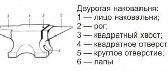
When building a receiver, amplifier or other radio equipment, a radio amateur has to deal with the work of remaking an old one or making a new transformer.
Radio amateurs who are starting such work for the first time often do not have a clear idea of how to wind, what material to choose and how to test the manufactured transformer.
Information on these issues, gleaned from magazine articles and books, is usually insufficient, and the radio amateur has to do most of the work, relying on his own ingenuity, or resort to the help and advice of a more experienced comrade.
Taking this into account, the author of this brochure has made an attempt to provide in a systematic form the necessary instructions for the manufacture of low-power transformers and teach practical techniques for winding them at home or in a radio circle.
Winding devices
In factories with mass serial or continuous production, transformers are usually wound on special, often automated machines. It is, of course, difficult for radio amateurs to rely on a special winding machine, and therefore they usually wind transformers either directly by hand, or using simple winding devices.
Let's look at how you can make simple winding devices from scrap materials and using ordinary tools.
The simplest such device is shown in Fig. 1. It consists of two racks 1 (or metal bracket), mounted on a board 2, and an axis 3 made of a thick (8-10 mm in diameter) metal rod, threaded through the holes in the racks and bent at one end in the form of a handle.
To wind the wire onto the finished frame 4, a wooden block 5 is made, slightly smaller in size than the frame window. A hole is drilled in the block to fit it onto the axle.
The frame is put on a block, which is then placed on the axle and secured there with a pin 6. To prevent the frame from dangling and moving off the block, a sealing wedge 7 made of hard cardboard or thin plywood must be inserted between them.
To avoid axial play when winding, which is very important for even laying of the turns, on the free sections of the axis between the block and the racks it is necessary to put on pieces of tubes 8, which can be made from metal sheets, wrapping them around axis 3.
Fig. 1. The simplest winding device. 1 - racks; 2 - board; 3 - axis; 4 - coil frame; 5 — block; 6 — pin 7-wedge; 5-tubes.
Fig. 2. Winding device from a drill. 1 - drill; 2- vice; 3 - rod; 4 - nuts.
To remove the wound frame, you need to remove the pin 6 and pull out the axis 3.
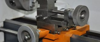
A more convenient and reliable winding device is made from a hand drill / (Fig. 2), which must be clamped in a vice 2 or attached to the table so that nothing interferes with the free rotation of the drill handle. A metal rod 3 is clamped into the drill chuck, onto which a block with a frame is mounted.
It is best to cut a rod with a diameter of 4-6 mm, and then the block with the frame can be clamped between two nuts 4. In this case, you can do without the block, clamping the frame with two cheeks made of plywood or PCB with holes in the center.
It is also convenient to use a ready-made machine for textile bobbins, a winder for rewinding film, a telephone inductor, etc. as a winding device.
The film winder is especially convenient (after a little modification), since it is made firmly and has a soft, play-free motion. Its alteration consists in replacing the short roller with a lock for film reels with a long axis with threads and wings for securing various frames.
No less important for winding work than the winding machine itself is the unwinding device, on which a coil of wire or the frame of an old transformer is placed, the wire of which is used for new winding. To prevent the insulation of the unwinding wire from deteriorating, and also to avoid shocks (which is important when laying turns in a row), the wire must run completely evenly.
The simplest device for unwinding wire is shown in Fig. 3. This is an ordinary metal rod 1, threaded into the holes of wooden posts 2, mounted on a board 3.
Making a wooden block for the frame of the unwinding coil 4 is not necessary in this case. To prevent it from hitting or jumping when unwinding, you can roll up a tube 5 of the required diameter from thick cardboard or paper, pass a rod through it and insert it tightly enough into the window of the frame.
Fig. 3. The simplest device for unwinding wire, 1 - rod; 2- racks; 3- board; 4 - coil with wire; 5 - tube.
Fig. 4. Machine for unwinding wire. 1 - bracket; 2 - board; 3-bolts; 4- hairpin; 5 — nuts (wings); 6 - cheeks.
It is better, however, to make a special unwinding device, shown in Fig. 4. From a strip of mild steel or other suitable material, bracket 1 is bent and attached to board 2 (or table).
In the vertical racks of the brackets, holes are made (5-6 mm in diameter) with threads (M-5 or M-6 thread), into which bolts 3, sharpened from the ends to a cone, are screwed. From a metal rod with a diameter of 5-6 mm, threaded along the entire length is made pin 4, at the ends of which shallow holes (3-4 mm) are drilled.
The cones and the pin are equipped with corresponding nuts (preferably wings) 5 and jaws 6 for clamping the coil or frame with the wire.
Very important in the winding process is the ability to accurately count the number of turns. A simple, but requiring special attention method is to verbally count each revolution (or every other revolution) of the machine handle. If the winding must contain a large number of turns, then it is more convenient, after counting a hundred turns, to make a mark on paper (in the form of a stick), then summing up all the marks.
Fig. 5. Connection of the thread counter with the winding device. a - using a flexible roller; b - using gears.
In a machine with a gear transmission, the gear ratio is taken into account, which should always be remembered.
It is much better to use a mechanical counter, which can be used as a bicycle speedometer or a counting mechanism from an electric meter, water meter, etc.
The meter can be connected to the machine using a flexible roller (a piece of thick-walled rubber tube) connecting the meter axis to the axis of the machine (Fig. 5a). In this case, each time you install a new frame, you have to disconnect the axle joint by removing the flexible roller, and after installing the new frame, put it on again.
A more convenient, but also more complex method of articulation is that the counter is connected to the machine through a pair of identical gears (Fig. 5,6). With this method, the counter is coupled to the machine all the time.
Frame for transformer
The transformer frame (or inductor) is needed to isolate the windings from the core and to keep the windings, insulating gaskets and terminals in order. Therefore, it must be made of sufficiently strong insulating material. At the same time, it must be made of a sufficiently thin material so as not to take up much space in the core window.
Typically, the material for the frame is thick cardboard (pressboard), fiber, textolite, getinaks, etc. Depending on the size of the transformer or inductor, the thickness of the sheet material for the frame is taken from 0.5 to 2.0 mm.
To glue the cardboard frame, you can use office universal glue or regular wood glue. The best glue with good moisture resistance should be considered nitro glue (enamel, rolled oats). Getinax or textolite frames are usually not glued together, but assembled “into a lock”.
Fig. 6. Proportionality of the frame and core plates. a - for split plates; b - for plates with a perforation of the middle core.
Based on the dimensions of the core, the shape and dimensions of the frame are determined, after which its parts are drawn and then cut. If transformer plates with a middle core cut are used, then the height of the frame is made several millimeters less than the height of the window so that the core plates can be inserted without difficulty.
To avoid errors, the dimensions of the core plates must be carefully measured (if they are unknown) and a sketch drawn on paper with the dimensions of individual parts of the frame. It is especially important to coordinate the individual parts of the frame when assembling it “into a castle”. The ratios of the dimensions of the frame and core plates for different types of plates are given in Fig. 6.
Fig. 7. Cutting and gluing the frame for the transformer.
A regular frame for a transformer can be made like this. First, the cheeks of the frame are cut out and a sleeve with cuffs on the end sides is cut out according to Fig. 7. Having made cuts at the folds, the pattern is rolled into a box, with side 1 glued to side 5. After that, both cheeks are put on the sleeve.
Then you need to bend the flaps of the sleeve and, spreading the cheeks to the edges of the sleeve, glue the flaps to the outer planes of the cheeks. You can glue pieces of the same cardboard from which the frame sleeve was made into the corners on the outside of the cheeks. If the glue is strong and reliable enough, then the sleeve can be made without flaps, gluing the cheeks directly to the edges of the sleeve.
Fig. 8. Details of the prefabricated frame for the transformer. a is the width of the core plate, plus the gap, plus the thickness of the material of parts 3; b - the thickness of the set of core plates plus the thickness of parts 2; in is the thickness of the material.
The prefabricated frame is more difficult to manufacture, but it has great strength and does not require gluing. Details of the prefabricated frame are shown in Fig. 8.
They are manufactured as follows. The dimensions from the sketch are transferred by marking to a sheet of material (textolite, getinax, fiber). If the material is not too thick, then the parts are cut out with scissors.
Then the grooves are cut into them using a file. In cheeks 1, after drilling several holes in them, windows are cut out.
Fig. 9. Assembling the frame for the transformer coils into a lock.
After this, having laid out the parts on the table, they adjust sides 2 and 3 of the sleeve so that when assembling the frame, all the cuts and protrusions of the “lock” come together. When marking and manufacturing parts 2, one of them can have a “key” part that is much larger in size (the contours are shown in dotted lines in Fig.
 for placing contacts or petals on it for soldering the winding leads. To avoid confusion of parts, they should be numbered before assembly. The order of assembly of the frame is clear from Fig. 9.
Immediately after making the cheeks, it is better to pre-drill holes for the leads in them “as a reserve”. When assembling the frame or gluing the cheeks, it is necessary to take into account which side of the transformer (or both) and which side of the cheeks the leads will be made in order to correctly position the sides of the cheeks that have holes for the leads.
It is necessary to pay attention to the fact that the sides of the cheeks with holes in the case of a square core section are not covered by the core plates.
The finished glued or assembled frame must be prepared for winding, for which you should round off the corners of the sleeve and cheeks with a file, and also remove burrs. It is useful (but not necessary) to coat or impregnate the frame with shellac, bakelite, etc.
Frame
Making a transformer frame with your own hands is not difficult. A suitable material for this is cardboard. The cavity inside the frame should be slightly larger in size than the body of the core, and the sidewalls should easily fit into the opening of the transformer. Using a round core, two coils are wound, and when using E-shaped plates, one is wound.
When using a round core from a laboratory autotransformer, you must first wrap it with insulating tape and only then wind the wire, distributing the required number of turns throughout the circle.
Having finished winding the primary layer of wire, it must be insulated with four layers of fabric insulation, and begin winding the turns of the secondary winding on top. Then the wire is completely wrapped with the same tape, leaving only the ends of the windings.
- a sleeve with bends at the ends is cut out;
- sidewalls are cut out of cardboard;
- according to the markings, roll the base of the coil into a small box;
- then it is sealed;
- supply the sleeve with sidewalls;
- Fixed with cuffs and glued.
Insulation pads
In some cases, a large voltage is generated between adjacent rows of transformer windings, and then the insulation strength of the wire itself is insufficient. In such cases, between the rows of turns it is necessary to place insulating pads made of thin thick paper, tracing paper, cable, capacitor or tissue paper. The paper should be smooth and, when viewed against the light, there should be no visible pores or punctures.
The insulation between windings in a transformer must be even better than between rows of turns, and the higher the voltage, the better. The best insulation is varnished cloth, but in addition to it, you also need thick cable or wrapping paper, which is also laid to level the surface for the convenience of winding on top of the next winding. One layer of varnished cloth is always desirable, but two or three layers of tracing paper or cable paper can be substituted.
Having measured the distance between the cheeks of the finished frame, you can begin preparing the insulating strips of paper. To ensure that the outer turns of the winding do not fall between the edges of the strips and the cheeks, the paper is cut into slightly wider strips than the distance between the cheeks of the frame, and the edges are cut by 1.5-2 mm with scissors or simply folded.
When winding, notched or folded strips cover the outermost turns of the winding. The length of the strips should ensure that the winding perimeter overlaps with the ends overlapping by 2-4 cm.
To insulate leads, solder points and winding taps, pieces of cambric or vinyl chloride tubes and pieces of varnished fabric are used.
To tighten and secure the beginning and end of thick windings (incandescent and output), pieces (10-15 cm) of keeper tape or strips, cut from varnished fabric and folded three or four times for strength, are prepared.
If the outer row of the winding is close to the core, then rectangular plates are cut out of a thin sheet of PCB or cardboard, which are inserted between the winding and the core after assembling the transformer.
Winding and output wires
The windings of transformers that a radio amateur has to deal with are most often made of PE or PEL enamel insulated wire.
In power transformers, exclusively PE wire is used for the network and step-up windings, and for the incandescent windings of lamps, the same wire or, with a large diameter (1.5-2.5 mm), a wire with double paper insulation of the PBD brand.
The terminals of the ends and taps from windings made with thin wire are made with a wire of a slightly larger cross-section than the winding wire. For them, it is better to take a flexible stranded wire with elastic insulation (for example, vinyl chloride or rubber). If possible, it is advisable to take wires with different colors so that you can easily recognize any output from them.
Leads from overstitching made with thick wire can be made with the same wire. Pieces of thin-walled insulating tubes must be placed on the ends or taps of these windings. The lead conductors must be of such length that they can be freely connected to the circuit elements or to the joint strip (comb).
Winding
A reel with a wire intended for the next winding is clamped between the removable cheeks of the threaded pin of the unwinding device. A pin with a coil is installed in the cones of this device (Fig. 4).
Depending on the diameter of the wire, the pressure of the cones and the degree of braking of the unwinding coil are adjusted. The coil must be clamped so that it does not break when unwinding, since the success and ease of laying the wire turn to turn depends on this. The unwinding device is located in front of the winding machine no closer than 1 m (further is better).
The prepared transformer frame is clamped between two cheeks loosely mounted on a pin.
Fig. 10. Location of transformer winding elements and winder arms.
The pin is then inserted into a drill chuck or clamped onto the shaft of a winding machine. The frame, as well as the coil with the wire, must be well centered so that it rotates evenly when winding and does not hit. The clamping brushes must be positioned in such a way that they do not cover the holes for the leads in the frame.
The coil with wire must be installed on the unwinding device and the winding machine on the table as shown in Fig. 10. The wire should go from the top of the coil to the top of the transformer frame.
The machine or drill is located above the table at such a height that there is a distance of 15-20 cm between the axis of the machine and the plane of the table, then when winding, the left hand can be freely placed on the table without interfering with the rotation of the machine with the frame.
Before you start winding, you need to prepare insulating gaskets, lead conductors, an insulating tube for the leads, a sheet of paper and a pencil for making marks when counting turns if you don’t have a counter, scissors for trimming the gaskets, a piece of fine sandpaper for stripping the insulation and a heated soldering iron for soldering of leads. You yourself need to sit freely against the table (workbench) and practice hand interactions.
With your right hand you need to rotate the winding machine so that the wire rests on the frame from above, and with your left hand you need to hold and pull the wire, directing its movement so that it lies evenly turn to turn (to do this, place your left hand on the table under the axis of the machine or device, pulling it forward as far as possible). The farther the wire is directed from the frame, the more accurately and easily the wire is laid.
Fig. 11. Termination of output wires of the transformer winding. a-regular termination of the output wire; b - winding during normal wire termination; c - lead wire blank with wide laying; g - winding when terminating a wire with a wide laying; d - termination of the last winding terminal; e - blank loop output wire.
The frame, verified and secured to a machine or drill, is wrapped in a thin paper strip. To keep the strip in place, you can lightly glue it.
The lead conductor or the end of the winding wire itself can be secured in two ways.
If the wire is thin, then the output is made with another, flexible wire. Such a lead should be long enough so that, after passing it through the hole in the frame, it is possible to wrap it (in one turn) around the frame sleeve.
Solder the stripped end of the wound wire to the tip of the output conductor, which has been previously stripped and tinned by 2-3 mm, and, having insulated the soldering point with a piece of paper or varnished cloth folded in half, winding begins (Fig. 11a). The insulating pad is pressed when winding with subsequent turns (Fig. 11.6).
The lead threaded into the hole in the frame must be somewhat disassembled around the axis (pin) of the winding machine or tied to it so that during further winding it does not pull out of the frame. For greater reliability, the leads can be tied to the sleeve with several turns of strong thread.
Another method is that the lead wire, after passing it through the holes in the cheek of the frame, is captured by a strip of release paper, the edge of which is folded under the wire (Fig. 11c). Then a strip, which should be the width of the frame, is wrapped around the sleeve and presses the lead wire.
In this case, under the strip (at the end of the output wire) you need to place an insulating pad, which will then cover the junction of the output and wound wires.
To the tinned end of the output wire protruding from under the gasket, located at the other cheek of the frame, solder the stripped tip of the wound wire and wind it. In this case, the insulating pad will be pressed by the first turns of the winding, and the output end will be pressed by the turns of its first row (Fig. 11, d).
Winding must be done slowly at first, adjusting the hand so that the wire goes and lies turn to turn with some tension. In the process of winding this row, the left hand should be moved evenly behind the laying of the turns, trying to maintain the angle of tension. Thus, subsequent turns of the first row press the previous ones.
Each row should not be wound up to the cheek of the frame by 2-3 mm in order to prevent the turns from falling through the cheek. This is especially important when winding high-voltage windings (for example, step-up windings in power or anode windings in output transformers).
Before starting winding (when the first terminal is tucked in and soldered), the revolution counter must be set to zero or its readings must be recorded. In the absence of a counter, the revolutions are counted silently or out loud, and every hundred revolutions is marked on paper with a stick.
After winding each row, the wire must be left taut so that when applying the paper gasket, the wound part of the winding does not unravel. To do this, you can press the wire to the cheek of the frame with a clothes clip. The gasket must cover the entire row of windings. It is glued together or temporarily (until it is held in place by the turns of the next row) pressed against the winding with a rubber ring, which can be made from a thin elastic cord.
The last output of the winding can be done in the same way as the first. Before winding the last complete or incomplete row, this output conductor, together with a paper gasket (Fig. 11, c), must be laid on the frame and, wrapping the frame with a strip of gasket, press the conductor with a rubber ring.
After winding the last row, the wound wire is cut and, after stripping, soldered to the tinned tip of the output conductor (Fig. 11e). If the output end must come out of the cheek, near which the last row of the winding ends, then the output end blank is made in the form of a loop (Fig. 11, e), which is laid on the frame in the same way as a regular output conductor.
Branches from part of the turns of the winding, wound with a not too thin wire (from 0.3 mm or more), can be made in the form of a loop with the same wire (without cutting it), as shown in Fig. 12, a. In this case, the loop is passed through the hole of a folded paper strip, which is tightened after pressing it to the winding with subsequent turns (Fig. 12.6).
You can do without a paper strip if you put an insulating tube on the loop-shaped outlet. Taps from a winding made with a thin wire (less than 0.3 mm) are usually made with a flexible lead conductor, which is soldered to the wire, as shown in Fig. 12, c.
Fig. 12. Taps from the transformer winding, methods of fastening. a - loop bend; b - sealing the loop branch; c - outlet from a separate wire.
Fig. 13. Fastening the ends of the transformer winding from thick wire. a - fastening the first winding terminal; b - fastening the last winding terminal; c - fastening two terminals with double-sided tightening.
The beginning and end of the thick wire windings are led out directly (without separate lead wires) through holes in the cheeks of the frame. You only need to put flexible insulating tubes on the ends coming out of the frame. The ends of the winding are secured using a narrow cotton tape.
The tape is folded in half, forming a loop into which the first output end of the wire is passed. Then holding the tape with your hand and wrapping 6-8 turns tightly around it, tighten the loop (Fig. 13a). The second output end of the winding is also secured.
In this case, without finishing the last 6-8 turns, a tape folded in a loop is placed on the frame, the last turns are wound, which press this tape to the frame, and, passing the end of the winding into the loop, the loop is tightened (Fig. 13.6).
If the winding of thick wire contains a small number of turns (no more than 10), then the lead ends can be secured with tape by tightening on both sides, as shown in Fig. 13, c.
In multilayer windings of thick wire, it is recommended to make paper spacers after each row. If the frame is not particularly strong, then each subsequent row should be made one or two turns less, and then fill the voids between the winding and the cheeks of the frame with twine or thread. This is important in the case when there are still other windings on top.
If the wire breaks during winding or when the winding is made from separate pieces of wire, the ends of the wires are connected as follows. For wires of small diameter (up to 0.3 mm), the ends are cleaned by 10-15 mm with sandpaper, carefully twisted and soldered. The junction of the wires is then insulated with a piece of release paper or varnished cloth.
The ends of thicker wires are usually soldered without twisting. Thin wires (0.1 mm or less) can be welded by twisting the ends by 10-15 mm (without stripping the insulation) and then placing them in the flame of an alcohol lamp, gas or several matches. The connection of the wires in this case is considered reliable if a small ball forms at the end of the twist.
Windings of thin wire with a number of turns of several thousand can be wound not turn by turn, but “in bulk.” However, the turns should be laid evenly so that the winding does not have bumps or dips. Approximately every millimeter of thickness of such winding, paper gaskets must be made.
To symmetry two windings or halves of windings, frames are often used, partitioned in the middle with a cheek. First, one half of the winding is wound, and then the frame is turned 180 degrees and the other half is wound.
Since the turns of each half of the winding will be wound in different directions, when connecting the halves in series, you need to connect their beginnings or ends. In this case, it is more convenient to make conclusions from the windings on opposite sides of the frame.
The windings of a transformer or inductor can be made without a frame. Winding is done basically in the same way as with the frame, but the spacers between the windings (or rows) are made very wide (three times wider than the winding).
Upon completion of winding of each section, the protruding edges of the gasket are cut at the corners with scissors or a safety razor blade and, bending them, the wound section is closed (Fig. 14). The end sides of the wound windings must then be filled with resin (from dry cells and batteries).
Fig. 14. Frameless winding of the transformer coil.
From the outside, if the top row of turns of the last winding is wound with thick wire and done fairly neatly, the coil does not need to be wrapped in anything. If the upper winding is made of thin wire, and is not wound turn to turn, then the coil should be wrapped in paper or leatherette.
In order to easily understand the leads and taps when installing the transformer, it is advisable to use multi-colored lead conductors. For example, make the terminals of the transformer network winding yellow, the beginning and end of the step-up winding red, the tap from the middle of the step-up winding and the wire from the screen black, etc.
You can, of course, use single-color output conductors, but then you need to put a cardboard tag with the appropriate designation on each output.
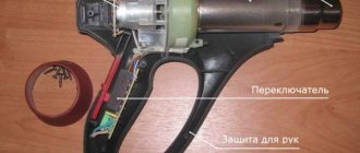
DIY winding machine
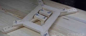
One possible option is to make a machine equipped with an adjustable stacker and a thread counter, using the principle of a bicycle wheel.
The wheel is placed on a pin in the wall, and its rim is equipped with a rubber ring. In order to put the core on the rim, you will first need to cut it and then fasten it again, obtaining a solid circle. Having wound the required length of wire around it, one end of it is connected to a core freely located on the rim. The coil moves along the rim in complete circles, as a result of which the wire is laid on the frame. In this case, a bicycle counter is used to count revolutions.
Creating a more advanced device will require the use of stepper motors with positioning of their position. For this, microcontrollers and an electronic counter are used. Such design requires certain skills in radio electronics.
The discovery of the principle of electromagnetic induction by the great scientist Faraday back in 1831 allowed us to take a fresh look at many laws of electrical engineering. It was based on the interaction of electromagnetic fields that 45 years after this, the great Russian scientist P. N. Yablochkov received a patent for the invention of a transformer. The classic definition is as follows: a transformer is an electrical device that converts the current of the primary winding of one voltage into the current of the secondary winding with a different voltage.
The induction effect is formed when the electromagnetic field changes, so for the transformer to operate, an alternating current voltage must be present. Transformation (transmission) is carried out by converting the electrical energy of the primary winding into a magnetic field, and then, in the secondary winding, the reverse conversion of the magnetic field into electrical energy occurs. If the number of turns of the secondary winding exceeds the number of turns of the primary winding, the device will be called a step-up transformer. When connecting the windings in reverse order, a step-down device is obtained.
Read also: Welding inverter best brands
Core assembly and terminal installation
Having finished winding the transformer, they begin to assemble its core. If the winding leads are made on one side of the cheek of the frame, then it is placed on the table with the leads down.
If the conclusions are made on both sides of the cheeks, then the frame must be positioned so that the largest number of conclusions and the thickest of them are at the bottom; the upper terminals must be folded several times and tied temporarily to the winding so that they do not interfere with the assembly of the core (Fig. 15, a). This is especially important when the core plates are shaped with notches on the middle core.
The power transformer core plates are assembled without a gap into a ceiling (alternately left and right), as shown in Fig. 15, b. The cores of output transformers or filter chokes are often assembled with an air gap, inserting plates only on one side (Fig. 15, c).
To ensure that this gap remains unchanged, a strip of paper or cardboard is inserted into the joint between the plates and the core pads. In plates with a notch on the middle core, the thickness of the gap is determined by the thickness of the notch.
Fig. 15. Assembling the core for the transformer. a - preparing a frame with windings for filling it with plates; 6 - assembly of the core plates into a “overlap”; c - assembly of the core plates at the joint with the gap; d - core assembly from plates with a perforation of the middle core.
If the frame is not very strong, then you need to fill it with plates (especially at the end of assembly) very carefully, since otherwise you can cut the sleeve with the sharp edge of the middle core and damage the winding. To prevent this, it is advisable to insert and bend a protective strip of mild steel into the frame window (Fig. 15, b).
When assembling a core from plates with a perforation of the middle core, you need to use an auxiliary guide plate (Fig. 15, d), cutting it, for example, from one core plate.
The frame window is filled with as many plates as possible. If the transformer has been disassembled and rewound, then when reassembling it, you must use all the previously removed plates. During the assembly process, the core should be pressed several times by inserting a ruler or rod into the frame window.
The last plates, if they fit tightly, can be driven in with a hammer, lightly hitting them through a wooden lining. After this, turning the transformer in different directions and placing it on a flat surface, it is necessary to straighten the core with light blows of a hammer through a wooden lining.
The core, after its assembly, must be well tightened. If there are holes in the plates, then it is tightened with bolts through overhead strips or angles (Fig. 16, a and b).
Along with this, you can also install a shield with petals for soldering the output ends of the windings.
A small core, assembled from plates without holes, can be tightened with one common bracket cut from thin mild steel (Fig. 16, c).
It is very convenient to use the chassis on which the transformer is to be installed to fasten the transformer and tighten its core. A window is cut out in the chassis for the passage of the lower part of the coil with leads, a transformer is installed and the core is tightened with bolts through a common overhead frame (Fig. 16, d).
The output ends are connected to the corresponding sections of the circuit either directly or through a shield with contact petals installed on the chassis.
Fig. 16. Transformer assembly. a and 6 - transformers with contact shields, fastened with bolts using strips and squares; c - transformer, tightened with a bracket (clip); d - transformer, bolted between the bar and the chassis.
The essence of the device
A transformer is an electronic device used to convert an alternating signal of one amplitude to another without changing the frequency. It is difficult to find electrical equipment that does not contain such a product in its circuit. It is a key link in the transfer of energy from one part of the chain to another.
The appearance of the transformer became possible after the invention of the induction coil in 1852 by the German mechanic Ruhmkorff. His device was similar to a spool for winding threads, but instead of the latter, wire was used. Inside the coil there was another similar structure. When current was applied to the lower coil, the voltage was also recorded on the upper coil. This was explained by a phenomenon called inductance.
It is not known for certain who exactly invented the transformer. In 1831, Faraday, while conducting experiments, discovered that electricity arises in a closed circuit when the magnetic field changes. He also drew a rough diagram of what the transformer should look like. Using a steel core and two coils in 1876, the Russian scientist Yablochkov actually made the prototype of a modern device. When a current was applied to one of them, he observed the occurrence of magnetic induction, leading to the appearance of a current on the other. At the same time, the voltage on the coils was different due to the different number of turns.
The appearance of such a design prompted other scientists to conduct research, which resulted in the technology for manufacturing a modern transformer.
Operating principle
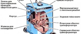
Modern industry produces transformers that differ in both appearance and characteristics. But they are all united by the principle of operation and five design elements. To understand how a step-down transformer works from 220 to 12 volts, you need to know these main parts of the product . These include:
- Core. In another way it is called a magnetic circuit. Its purpose is to conduct magnetic flux. Based on the type of execution, cores are divided into three groups: planar, strip, and molded. They are made from electrical steel, ferrite or permalloy, that is, materials that have the ability to be highly magnetized and have conductive properties.
- Windings They are a conductive wire wound in turns. The material used for its manufacture is copper or aluminum.
- Frame. It is used for winding windings on it and is made of insulating material.
- Insulation. Protects coils from interturn short circuits, as well as their direct contact with conductive parts of the structure. The most commonly used materials are varnish, clipper tape, and varnished cloth.
- Mounting terminals. To prevent breakage of the windings during installation, special terminals are made in the structure, allowing the power source and load to be connected to the transformer.
The main part of the winding is the turn. It is because of this that a magnetic force is created, which subsequently leads to the appearance of an electromotive force (EMF).
Thus, the transformer is a closed circuit (core) on which coils (windings) are located. Their number can be two or more pieces (with the exception of an autotransformer). The coil connected to the power source is called primary, and the one connected to the load is called secondary.
You might be interested in why you need a choke, its types and characteristics
When connected to a source of alternating energy, a time-varying current (sinusoidal) begins to flow through the primary winding of the device. It creates an alternating electromagnetic field. The magnetic induction lines begin to penetrate the core in which they are short-circuited. As a result, an emf is induced on the wound turns of the secondary coil, which creates a current when the terminals are connected to the load.
Characteristics and types of product
The potential difference arising between the terminals of the secondary winding depends on the transformation ratio, which is determined by the ratio of the number of turns of the secondary and primary coils. Mathematically, this can be described by the formula : U2/U1 = n2/n1 = I1/I2, where:
- U1, U2 - respectively, the potential difference on the primary and secondary windings.
- N1, N2 - number of turns of the primary and secondary coils.
- I1, I2 - current strength in the windings.
Based on the type of core, 12 V transformers are divided into ring, W-shaped and U-shaped. According to their design, they are: armored, rod and toroidal (ring). The rod type is assembled from U-shaped plates. The armored version uses side rods without windings. This type is the most common, since the windings are reliably protected from mechanical damage, although the cooling efficiency decreases.
The toroidal transformer has the best characteristics. Its design promotes good cooling. Effective distribution of the magnetic field increases the efficiency of the product. This type is the most popular among radio amateurs, as the simplicity of the design allows it to be quickly disassembled and assembled. For example, very often, it is on the basis of a torus that homemade powerful welding machines are made.
The main parameters of the product include:
- Power. Indicates the amount of energy transmitted through a device without causing damage to it. It is determined by the thickness of the wire used to wind the coils, as well as the dimensions of the magnetic circuit and the frequency of the signal.
- Efficiency It is determined by the ratio of the power spent on useful work to the power consumed.
- Transformation coefficient. Defines the conversion method.
- Number of windings.
- Short circuit current. Determines the maximum current that the device can withstand without burning out the windings.
You may be interested in this How to use a digital multimeter: setup recommendations
The simplest tests
The transformer, after its winding and assembly, must be tested. Power transformers are tested by connecting the primary (mains) winding to the electrical network.
To check the absence of short circuits in the transformer windings, we can recommend the following simple method. An electric lamp L (Fig. 17), designed for the corresponding network voltage, is connected to the network in series with the primary winding of the transformer being tested.
For transformers with a power of 50-100 W, take a lamp of 15-25 W, and for transformers of 200-300 W - a lamp of 50-75 W. If the transformer is working properly, the lamp should burn at approximately “quarter incandescence.”
If you short-circuit any of the windings of the transformer, the lamp will burn almost fully incandescent. In this way, the integrity of the windings, the correctness of the conclusions and the absence of short-circuited turns in the transformer are checked.
After this, making sure that the winding terminals are not shorted, the primary winding of the transformer must be connected directly to the network for one to two hours (by closing lamp L with the Vk switch). At this time, you can use a voltmeter to measure the voltage on all windings of the transformer and make sure that their values correspond to the calculated ones.
Fig. 17. Scheme for testing transformer windings.
In addition, it is necessary to test the reliability of the insulation between the individual windings of the transformer. To do this, one of the output ends of the step-up winding II must alternately touch each of the outputs of the network winding 1.
In this case, the voltage of the step-up winding, together with the voltage of the mains winding, will act on the insulation between these windings.
In the same way, by touching the output end of step-up winding II to the output ends of other windings, the insulation of these windings is tested. The absence of a spark or weak sparking (due to the capacitance between the windings) indicates the adequacy of the insulation between the windings of the transformer.
The transformer must be tested carefully, being careful not to come under the high voltage of the step-up winding.
Other types of transformers (output transformers, etc.) with windings of a sufficiently large number of turns are tested in the same way. By measuring the voltage on the windings of the transformer, the transformation ratio can be determined.
Having verified as a result of the test that the manufactured transformer is in good working order, the latter can be considered ready for installation and assembly.
Calculation of product parameters
Before winding a toroidal transformer at home, you will need to calculate its values. To do this you need to know the source data. These include: the output voltage, the outer and inner diameter of the core.
The power of the device is determined by the product of the areas S and Sо, multiplied by the coefficient: P=1.9* S * Sоk.
The cross-sectional area is calculated using the formula: S=h*(Dd)/2, where:
- S - cross-sectional area;
- h - height of the structure;
- D - outer diameter;
- d is the internal diameter.
To calculate the window area, the formula is used: Sok=3.14*d2/4.
The number of turns in the secondary winding is equal to the product W2=U2*50/Sok.
Next, it remains to calculate the number of turns in the primary. For this, the expression is used: W1=(Uin*W2)/Uout, where Uin is the input voltage, and Uout is the voltage at the output of the device.
This calculation method can be applied to almost any type of toroidal transformer. But for the calculation of some products there is its own methodology.
Welding device
This type of transformer is characterized by a high output current. The maximum current and voltage are used as input parameters. For example, for a device with a welding current of 200 amperes and a voltage of 50 volts, the calculation is as follows:
Read also: Checking the performance of the Schottky diode sr56ked
1. The power of the transformer is calculated: P = 200 A * 50 V = 1000 W.
2. The window cross-section is calculated: Sok = π * d2/ 4 = 3.14 * 144 / 4 (cm2) ≈ 113 cm².
3. Cross-sectional area: Sc=h * H = 2 cm * 30 cm = 60 cm².
4. Core power: Рс = 2.76 * 113 * 60 (W) ≈ 18712.8 W.
5. Number of turns of the primary winding: W1 = 40 * 220 / 60 = 147 turns.
6. Number of turns for the secondary winding: W2 = 42 * 60 / 60 = 42 turns.
7. The area of the secondary wire is determined based on the highest operating current: Spr = 200 A / (8 A/mm2) ≈ 25 mm².
8. The area of the primary wire is calculated: S1 = 43 A / (8 A/mm2) ≈ 5.4 mm².
This calculation option is applicable not only for welders, but can also be successfully used for other types. As you can see, no difficulties should arise during the calculation.
Current transformer device
It is not difficult to make a current transformer with your own hands, but before making it you will need to perform a calculation. This calculation differs from the generally accepted one due to the design features of the product. It starts with the required value of the secondary current (unit ampere): Iam = Iper / Ivt, where:
• Iper - the value of the primary winding current, multiplied by the number of turns in it;
• Ivt - the number of turns in the secondary winding.
In order to figure out how to correctly perform the calculation, it is easier to consider a practical example of a homemade current device. Let it be necessary to obtain 4 volts at the output of the current device, and limit the current to 5 amperes.
The step-by-step calculation method looks like this:
- Take a ferrite ring, for example 20x12x6 from 2000hM.
- 100 turns of wire are wound. These turns constitute the secondary winding, since the primary is simply one turn of wire passed through ferrite.
- The value of the current in the secondary will be equal to: I/Ktr = 5 / 100 = 0.05 A. where Ktr is the transformation ratio of the transformer (the ratio of the number of primary windings to the secondary).
- The size of the load shunt is calculated according to Ohm's law: R = U/I. It turns out R= 4/0.05 = 80 Ohm.
In this way, calculations can be performed for any required parameters. Regardless of the shape of the current at the input, the voltage at the output of the current device is always bipolar. It is the resistance, not the diode, that is used as the secondary winding shunt. If there is a need for a diode, then a resistor is connected first, and then a diode or diode bridge. In the second case, the resistance is included in the diagonal of the bridge.
Lookup tables
Table 1. Characteristics of copper enameled wires PEL and PShO.
Table 2. Number of turns per centimeter of continuous winding length.
Table 3. Output transformer data from some radio receivers.
Source: A. N. Podyapolsky. How to wind a transformer.