Today, the welding inverter is actively used not only for industrial needs, but also at home. This is due to its excellent functional and manufacturing advantages.
If you are well versed in electronics, then having diagrams and manufacturing instructions, you can make an inverter welding machine with your own hands, while spending money only on consumables. This option is suitable for people who like to buy good quality equipment. Inverter devices from well-known companies are very expensive, and cheap ones will only bring disappointment from use.
In order to start constructing a homemade welding inverter, you need to carefully work on its circuit: study the entire design, understand the electronics, and prioritize the work.
The structure of a homemade inverter
Almost all home-made welding inverters have the following basic elements:
- Power unit;
- Power key drivers;
- Power part.
When designing a welding inverter, it is important to navigate its characteristics:
- The maximum current consumption is 32 A;
- During operation, a current of no more than 250 A is used;
- To perform welding work, a sufficient mains voltage of 220 V;
- For work, electrodes with a diameter of 3-5 mm and a length of 10 mm are used.
- The resulting device will have efficiency indicators no less than the professional version of the device.
Advantages and disadvantages of an inverter device
The advantages are the following parameters:
- Weight - no more than five kilograms. This is an undeniable advantage, because it makes it possible to easily transport it or simply move it within the workshop.
- It is able to continue to work even when the voltage drops, without turning off, like a transformer device.
- The device operates with direct and alternating current.
Conditional disadvantages can be called:
- High cost of the device.
- It must be periodically cleaned of dust.
But due to the fact that the device will be made by hand, the first disadvantage is not so relevant. Periodic maintenance is necessary for any device, so cleaning will guarantee its smooth operation.
Also, for the operation of the device, you must acquire special skills and be careful when operating it.
DIY welding machine diagram
When you have decided that you will build the inverter apparatus yourself, the first step is to draw up a diagram .
You need to consider and provide for ventilation of the device’s mechanisms, as this is extremely important to avoid overheating of the parts inside. The simplest and optimal solution would be to use radiators from Pentium 4 and Athlon 64 system units. These components are commercially available and have a low price.
The diagram must provide for the presence and location of brackets that will secure the transformer.
Preparatory work before assembling the device
When the device diagram has been drawn up, it is necessary to proceed to the preparation of components and parts. To assemble the inverter with your own hands, you will need the following materials:
- Copper wires;
- Cotton fabric;
- Electrical steel;
- Fiberglass;
- Textolite.
To avoid problems with voltage drops, it is necessary to wind across the entire width of the frame. In the specifically proposed version of the device there will be 4 windings:
- Primary. It will include 100 turns, PEV 0.3 mm;
- Secondary first - 15 turns, PEV 1 mm;
- Secondary second - 15 turns, PEV 0.2 mm;
- Secondary third - 20 turns, PEV 0.3 mm.
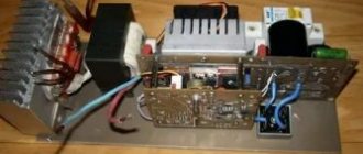
The board and power supply are installed separately from each other, with a sheet of metal located between them. To attach it to the housing of the welding inverter, it is necessary to use welding seams.
To control the shutters, it is necessary to install conductors. Their length should be no more than 15 cm; there are no special requirements for the cross-section. When assembling the device, it is necessary to study the diagram for it in detail, to understand all the important points of connecting the parts to each other.
The power supply must be covered with a shielding winding . It is made from a similar wire. All turns of the cover must have the same direction as the primary ones and completely overlap them. There must be insulation between each winding. You can use varnished cloth or masking tape for it.
When putting the power supply into operation, you need to work on selecting the required resistance. It must be balanced so that the power supplied to the relay is within 20-25 V.
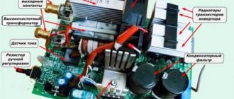
Carefully select radiator elements for input rectifiers. They must be powerful and reliable. Used computer parts have proven themselves to be excellent. They are available for sale on the radio market.
The welding inverter requires 1 thermal sensor . It is installed inside the radiator. To regulate the current in the arc, a PWM controller is purchased and installed on the control unit. The capacitor will produce a PWM voltage, and the parameters of the welding current will depend on this.
Manufacturing of transformer and choke
The main task of the transformer is to convert the voltage of high-frequency current with sufficient strength. The cores can be used model Ш20×208, in the amount of two pieces. You can create the gap between the parts yourself using plain paper. The winding is made with your own hands, with a copper strip 40 mm wide, the thickness should be at least 0.2 mm. Thermal insulation is achieved using cash register thermal tape; it demonstrates good wear resistance and strength.
How to make a transformer for an inverter
The use of copper wire when winding the core is unacceptable, because it forces current onto the surface of the device. To remove excess heat, a fan or cooler from the computer power supply, as well as a radiator, are used.
The inverter unit is responsible for the throughput of the electric arc through the use of transistors and chokes.
For a stable welding process, it is recommended to use several transistors in a parallel circuit rather than one more powerful element.
Due to this, the output current is stabilized; during the process of inverter welding with your own hands, the device produces less noise.
Homemade choke
Capacitors connected in series are responsible for several functions:
- Resonant emissions are minimized.
- Ampere losses due to the design features of transistors, which open much faster than they close.
Homemade transformer as the basis for an inverter
Transformers become very hot due to the large volume of current passing. Radiators and fans are used to control the temperature. Each element is mounted on a radiator made of heat-dissipating material; if it is possible to install one powerful cooler, this will reduce assembly time and simplify the design.
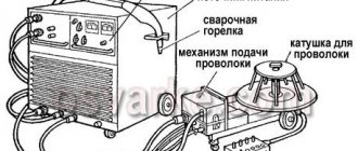
Assembling an inverter welding machine
Having purchased all the necessary parts for the welding inverter, we proceed to its assembly. Before installing parts, check that they are in good condition. Find a ready-made inductor and start winding it. To do this, you need to use PEV-2 wire . The required number of turns is 175. The selected capacitor must have a voltage of at least 1000 V. If you cannot buy one capacitor with this voltage, you can install several so that their total capacity is 1000 V.
Try not to use one powerful transistor in the installation; it is better to replace it with several, less powerful ones. These indicators affect the operating frequency, which leads to the formation of large noise effects during welding work. If you incorrectly calculate the required power of the device, this will lead to rapid breakdown and repair work.
When assembling the welding inverter begins, it is imperative to maintain the distance between the winding and the magnetic cores. A PCB plate must be placed between the layers of the winding. This will help increase the electrical safety of the device and achieve fast and sufficient cooling.
Next, we move on to attaching the transformer to the very base of the homemade inverter. For this, 2-3 staples are used. They can be made from copper wire with a diameter of 3 mm. For boards, you can use foil PCB with a thickness of 0.5-1 mm. Be sure to make narrow cuts in the plates; they will help to freely remove the diodes to avoid overloads.
When all the main elements of the device have been assembled, you can proceed to attaching it to the base. The base itself can be made from getinax plates. For normal operation, a plate with a thickness of 0.5 cm is suitable . Be sure to cut a round window in the center of the plate; a fan will be fixed there, which must be protected with a protective grille. When installing magnetic cores, do not forget to leave gaps for free air flow.
On the front side you need to install a toggle switch handle and LEDs, cable clamps and a variable resistor handle. This will be the design of an almost finished welding machine. It is placed in a casing 4 mm thick. A button is installed on the electrical wire holder. Thoroughly insulate the cable that is connected to it and the wires.
Setup and testing
The quality of the weld and the safety of the welder directly depend on the correct settings of the finished machine. There are several parameters to check:
- The tungsten electrode must be sharpened to a minimum diameter.
- The collet on the torch and the diameter of the electrode must match. Checked by installation.
- When the valve is open, the argon flow rate should optimally be 12-15 l/min. Adjustable by gearbox.
- Ignition of the arc.
Be sure to check the device before use
Arc ignition testing is carried out in several steps, very carefully and slowly. You need to turn on the oscillator and bring the burner with the electrode to the metal with the connected ground. Press the power button. At this moment, an arc appears at a distance of about 0.5 mm. Release the button. Open the gas supply, press the power button again. With gas it should appear at a distance of 1 cm.
It is better to test a homemade welding machine immediately after assembly and not on working parts. For a test weld, the current settings are selected in accordance with the metal, and the filler wire is selected. To assess the performance of the device, you can try to melt massive parts, check the uniformity of deposition of the filler wire, and carefully monitor the argon envelopment of the weld pool (there is no oxidizing film or carbon deposits).
Setting up the welding inverter for operation
Having assembled the entire mechanism, it is necessary to correctly and competently configure it and put it into operation. There are situations where it is difficult to resolve the issue on your own and you have to seek the help of a specialist.
- The first step is to connect the device to a 15V PWM power supply; one of the convectors is also connected in parallel. This will help avoid overheating of the device, and the noise level will be significantly lower.
- In order for the resistor to close, a relay must be connected. It is put into operation after the capacitors have finished charging. This will help to avoid large voltage fluctuations when connecting to a 220V network. If you neglect to connect the resistor directly, an explosion may occur.
- Next, careful monitoring of the operation of the resistor closure relay is necessary when it is connected to the current on the PWM board. It is imperative to diagnose the presence of pulses on the board after the relay is activated.
- Then we supply 15V power to the bridge. This helps to check its normal and proper operation and correct installation. The current on the device should not exceed 100A. In this case, the speed should be idle.
- It is imperative to check the correct installation of transformer phases. You can use a 2-beam oscilloscope for this. To do this, you need to supply 220V power to the bridge from the capacitors through the lamp, setting the PWM frequency to 55 kHz. Having installed the oscilloscope, look at the signal form and observe that the voltage should not exceed 330V. to calculate the oscillation frequency of a transformer. It is necessary to gradually reduce the PWM frequency until the lower IGBT switch produces a slight turn. This indicator must be divided by 2, and the resulting quotient added to the value of the supersaturation frequency. The current consumption parameters of the bridge should not be higher than 150 mA. Follow the light from the light bulb. Very bright indicates problems with the winding; a breakdown is possible in it. There should be no noise effects coming from the transformer. If there is any noise, pay attention to the correct polarity. As a test control on the bridge, you can use a 220V electric kettle. All conductors from PWM must be crowded together and located away from sources of interference.
- Using resistors, it is necessary to gradually increase the current. At the same time, listen to extraneous noises and sounds, watch the oscilloscope readings. The readings of the lower key are no more than 500V. The norm is 240V.
- Welding work must begin within 10 seconds. Then the radiators are checked. If they are cold, then the work lasts another 20 seconds. Further, the time increases to 1 minute.
Self-production of a powerful inverter 12-220 at 500 watts
When it is necessary to create mains voltage in a car, special 12-220 converters are usually used. There are inexpensive standard inverters on sale for about 20-30 dollars. However, the maximum power of such devices is, at best, about 300 watts. In some cases, this power may not be enough.
You can get power for a powerful amplifier through small transformations. It is enough just to replace the secondary winding on a standard inverter. After this, you can get any value of the input voltage. For example, the power of a 400 Watt inverter will increase to 600 Watts.
To increase power at home, experts recommend using a simple method. It will be necessary to replace the high-power bipolar switches with IRF 3205.
An inverter is used for operation, to which it is possible to connect 4 pairs of output transistors. Therefore, the device, after carrying out the necessary work, will be able to produce a power of about 1300 watts. If you buy a ready-made inverter with such parameters, its cost will increase to 100-130 dollars.
It is worth noting that the traditional push-pull circuit of the device does not contain protection against overheating, short circuit and output overloads.
The generator is based on a TL 494 microchip, which has an additional driver. It is necessary to replace low-power bipolar transistors with domestic analogues (KT 3107).
In order not to use powerful switches to supply power, the inverter is equipped with a remote control circuit.
In the driving part of the device, special SCHOTTTKI diodes type 4148 are used (domestic KD 522 is also suitable). The transistor in the remote control circuit is replaced with KT 3102.
After this, you can move on to the most important part of the project - the transformer. This element is wound on a pair of glued 3000 NM rings. Moreover, the size of each of them is 45x28x8. For a tighter fixation, the rings can be wrapped with tape.
Then the rings are wrapped on top with fiberglass (the cost in the store is no more than $1). It is quite acceptable to replace this material with fabric electrical tape.
Fiberglass is cut into small strips about 2 cm wide and no more than 50 cm long. The material for work has high heat resistance, and thanks to the thin base, the insulation looks neat.
For the primary winding you need 2x5 turns of wire, that is, 10 turns with a tap from the middle. The work is carried out with a wire with a diameter of 0.7-0.8 mm, and 12 wires are used for each arm. The process is presented more clearly in the following photographs.
The tourniquet is stretched, and 5 turns are evenly wound on both arms, stretching them across the entire ring. The windings must be the same.
The resulting elements have four outputs. The beginning of the first winding must be soldered to the end of the second. The solder location will be a tap for a power voltage of 12 V.
At the next stage of work, the ring must be insulated with fiberglass and covered with a secondary winding.
The secondary winding increases the output voltage. Therefore, when carrying out work you need to be as careful as possible and follow all safety precautions. It is worth remembering that high voltage is dangerous. Installation of the device is carried out only with the power turned off.
The winding of the rings is carried out using a pair of parallel strands of 0.7-0.8 mm wire. The number of turns is about 80 pieces. The wire is distributed evenly throughout the ring. At the final stage, the product is additionally insulated with fiberglass.
When the inverter assembly is completed, you can begin testing it. The device is connected to a battery; for starters, a battery with a voltage of 12 V from an uninterruptible power supply will do. In this case, the “plus” of power will go to the circuit through a 100-watt halogen lamp. It is worth paying attention that this lamp should not be lit before or during work.
After this, you can proceed to checking the field keys for heat generation. With a correctly assembled circuit, it should be practically zero. If there is no input load, and the transistors overheat, then you need to look for a non-working component in the device.
If the testing was successful, you can install the transistors on one common heat sink. For this purpose, special insulating gaskets are used.
The circuit diagram in *.lay format is in the archive file and will be available after downloading:
We recommend:
Rules for maintenance and repair of welding equipment
For proper and long-term operation of the device, it is necessary to periodically check and monitor each structural element. This will make your repair work easier and reduce it to a minimum. If the unit breaks down, find the cause of the problem and carry out repair work.
To perform this work, you must have the following tools:
- Soldering iron;
- Vacuum cleaner;
- Screwdriver;
- Tester;
- Brush.
The first and main cause of failure may be the rectifier. Through it, alternating current is converted into direct voltage. A surge protector makes it possible to smooth out voltage fluctuations. The transistor circuit is responsible for generating a single-phase high-frequency voltage. The unit regulates the operation of the keys using feedback signals, so it can change the operating mode of the inverter. The cooking transformer is responsible for reducing the voltage, then the valve blocks rectify it and supply it to the electrode.
DIY welding inverters
If the welding machine breaks down, remove the housing cover and blow it out with a regular vacuum cleaner . Areas that are difficult to clean using this method should be treated with a brush or cloth. Begin diagnosing the input circuit. Check if the inverter is receiving voltage. If it is not there, then repair the power supply. The fuses may have blown. It’s not difficult to create a welding inverter with your own hands, but repairs, if diagnosed incorrectly, can take a lot of time.
Next, start diagnosing the temperature sensor. Compare the nominal indicators with the existing ones. This element cannot be repaired and must be replaced with a new one. Then, the basic elements of the device are studied. If you see darkening on one of them, this means that the soldering was performed poorly during assembly. Use a tester to check the connection circuits.
If the contacts are made poorly, this leads to overheating, breakdown and expensive repairs of the inverter. Check the connectors, if they are loose - tighten them, if there is a bad connection - solder them. If during welding work there is spattering of metal, sticking of the electrode, or burning of an arc, then it is necessary to adjust the current supply or replace the electrodes.
Make sure the cable is in good condition; if it is bent, replace it with a new one immediately. Only in this case will an inverter welding machine, created with your own hands, work efficiently and reliably.
Specifics of argon welding
Argon welding differs from MMA welding in several process details:
- Welding takes place with constant argon blowing onto the seam.
- Tungsten electrode (for manual welding). Consumable electrodes can also be used for automatic argon welding.
- The arc is ignited using an oscillator - a device for non-contact ignition.
- Specific technique for passing the electrode.
- Filler wire required. Without it, you can only cook very thin sheets.
- Works on both direct current (reverse polarity) and alternating current.
It is quite possible to make argon welding from an inverter, and a homemade installation will pass the most complex seams, producing excellent quality. Argon differs from other working gases by being completely inert to most substances. It is cheap, heavy enough to tightly envelop the pool during the welding process, and prevents the formation of an oxide film. This is also its disadvantage - when working outdoors, the wind can reduce the quality; a shelter made from scrap materials will correct the situation.
Functionality of the welding inverter
In an inert gas environment, welding takes place with a current of 20-200 A and a voltage of 30-80 V. The parameters are selected from a range using special tables and depend on the thickness of the sheet being joined and the diameter of the electrode. Tungsten for argon welding does not melt at operating temperatures, allows you to obtain a narrow, neat but durable seam due to a very thin arc and shows low consumption (evaporation - 0.01 g/m).
Filler wire on thick parts is needed to obtain a monolithic weld and is selected taking into account the material of the elements being welded. For aluminum you need aluminum wire, for stainless steel - alloy steel of a certain grade, and so on for each material. At the operating temperature of argon welding, it melts and fills the seam efficiently.