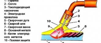
Principle of operation
The included gas torch for the semi-automatic machine is an actuator for producing a welding seam in a shielding gas environment.
Gas burner for semi-automatic machine
The operating principle is as follows:
- The torch is placed to the base metal at the arc formation distance.
- Before the arc starts, shielding gas is supplied to the welding zone for a few seconds.
- Voltage is supplied to the current-carrying tip, and accordingly to the electrode wire.
- In the welding arc, the electrode wire melts and drops with the gas flow into the weld pool.
- When the torch moves along the elements being connected, a weld seam is formed.
- The protective gas environment ensures a high-quality and clean seam.
During welding work, torch elements are exposed to high temperatures. Particularly affected are the gas nozzle, the current carrying tip and the electrode holder, also called the diffuser and gas divider.
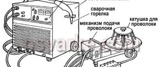
Burner device for semi-automatic machine
- burner base;
- insulating ring;
- electrode holder;
- current carrying tip;
- gas nozzle.
Failure of, for example, the current-carrying tip prevents the supply of welding wire to fill the pool.
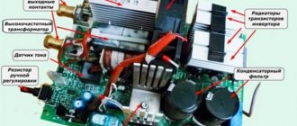
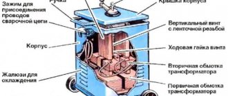
↑ Diagram and details of the welder
A single-phase 16A type AE circuit breaker is used as a power and protection switch. SA1 - welding mode switch type PKU-3-12-2037 with 5 positions.
Resistors R3, R4 are PEV-25, but they don’t have to be installed (I don’t have them). They are designed to quickly discharge choke capacitors.
Now for capacitor C7. Paired with a choke, it ensures combustion stabilization and arc maintenance. Its minimum capacity should be at least 20,000 microfarads, optimal 30,000 microfarads. Several types of capacitors with smaller dimensions and higher capacity were tried, for example CapXon, Misuda, but they did not prove to be reliable and burned out.
Power thyristors for 200A are taken with a good margin. You can install it at 160 A, but they will work at the limit, and you will need to use good radiators and fans. The used B200s stand on a small aluminum plate.
Relay K1 type RP21 for 24V, variable resistor R10 wirewound type PPB.
When you press the SB1 button on the burner, voltage is supplied to the control circuit. Relay K1 is activated, thereby, through contacts K1-1, voltage is supplied to the electromagnetic valve EM1 for acid supply, and K1-2 - to the power supply circuit of the wire drawing motor, and K1-3 - to open the power thyristors.
Switch SA1 sets the operating voltage in the range from 19 to 26 Volts (taking into account the addition of 3 turns per arm up to 30 Volts). Resistor R10 regulates the supply of welding wire and changes the welding current from 30A to 160A.
When setting up, resistor R12 is selected in such a way that when R10 is turned to minimum speed, the engine still continues to rotate and does not stand still.
When you release the SB1 button on the torch, the relay releases, the motor stops and the thyristors close, the solenoid valve, due to the charge of capacitor C2, still remains open, supplying acid to the welding zone.
When the thyristors are closed, the arc voltage disappears, but due to the inductor and capacitors C7, the voltage is removed smoothly, preventing the welding wire from sticking in the welding zone.
Prevention measures
To avoid many breakdowns of a semi-automatic welding machine, it needs proper care and proper operation. The device often operates in difficult conditions (high room humidity, dust or smoke in the working area, low or, conversely, high air temperature, long welding operations with short pauses, and so on). All this leads to a decrease in the uptime of the unit.
Experts and manufacturers of welding equipment recommend optimal timing for carrying out preventive measures with machines, aimed at preventing the most common malfunctions.
It is necessary to carry out a technical inspection of all equipment at least once a month, including in this event not only the identification of obvious (or possible) malfunctions or irregularities with the equipment, but also the following work:
- mandatory cleaning and tightening of terminal blocks, contacts, screws and clamps;
- replacement of burnt insulation of wires and cables;
- blowing air or inert gas under pressure on internal and external devices to remove dust and other dry contaminants;
- cleaning the electronic control board with a neutral solvent;
- checking the correct operation of the fan and refrigerators.
Troubleshooting other problems
Problems with the piezoelectric element are the most common “disease” of gas burners, but they are far from the only one, since other parts can also fail. This is especially true for devices that are used for a long time and “mercilessly”. In any case, the structure will have to be completely disassembled and then carefully inspected.
Do-it-yourself gas burner repair may be required if a malfunction is detected in the operation of the nozzle. There are two options here.
- Heavy pollution. This trouble occurs if gas was used to refuel the burner, the quality of which is far from ideal. The best option is to use lighter gas. Due to the accumulated dirt, fuel will not be able to enter the burner, which means there will be nothing for the device to work on. Cleaning the nozzle is a method that is quite accessible at home.
- The second problem inside the nozzle is the ring falling out. A common reason is the appearance of cracks in it due to strong heating. The consequence is the impossibility of igniting the burner, since the spark will fly in different directions. In this case, repairing a gas burner will consist of making a homemade element. For example, a similar ring can be made from copper wire.
How do you repair a gas burner yourself if the source of the problem is the nozzle? In both cases, the technician has the opportunity to fix the problem himself.
Cleaning the nozzle yourself
Checking the nozzle for blockage is quite simple. You need to remove this element, then look through the hole into the light. If the white “spot” is not visible, then the “diagnosis” can be considered confirmed, so cleaning is necessary. However, there is one big obstacle to this operation. This is a small hole for which it is very difficult, almost impossible, to pick up a needle or thin wire.
Therefore, it is not always possible to mechanically clean the nozzle. Another disadvantage of “violent” actions is the risk of widening the hole. Such a defect will inevitably affect the operation of the burner - the flame will burn incorrectly: its height cannot be predicted. For this reason, experts recommend using two other methods.
- Blowing out dirt. This method is suitable if the contamination is not yet too serious. The nozzle is removed, then pressed against the gas cartridge with the side with the hole, and begin to blow through. There is a chance to get rid of the interference in such a simple way. Instead of compressed gas, you can try using a powerful jet of water.
- The nozzle gets very hot. It should be noted that this option refers to cardinal, even brutal decisions. Craftsmen use it at their own peril and risk, since a possible outcome is destruction (burning) of the part. A wire is attached to the removed nozzle and then heated red-hot using a second burner. After this, the part is dipped in cold water.
If you choose the best option, then it can be called the first, more gentle one. But it is also not always effective. Therefore, many consider it optimal to search for a thin wire and then sharpen its tip. One of the places where you can “get” a super-thin needle is a tattoo parlor (art tattoo studio). In this case, there is a chance to guarantee both the result and the safety of the part.
However, there are times when even these methods are powerless. Then, instead of cleaning or heating, they use a solvent wash, which is distributed with a soft brush. Some owners, after treating with gasoline, blow out the part using a pump. They say that this “tandem” always helps to get rid of blockages. Another rescue option is a product designed for cleaning carburetors.
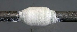
Replacing the nozzle ring
When a gas burner is used intensively, the ring operating at high temperatures falls out after a certain period of time and is then completely lost. Due to damage or loss of such a part, it is unlikely that anyone will decide to buy a new gas burner. Finding a suitable replacement is also not the best solution, so the owner is left with the only option. This is making a ring with your own hands.
The material of the original element is brass, but purchasing it is not advisable, since such a ring will be equal in cost to the price of a new gas burner. Copper, or rather ordinary copper wire, can become a full-fledged replacement for this expensive alloy. Its cross section is 2.5 mm. To create a new part, first cut a piece to the required length. Then the wire is bent, focusing on the diameter of this nozzle element.
Repairing a gas burner with your own hands will be a quick process only if the diagnosis is carried out correctly. How to distinguish between a ring falling out and a clogged nozzle? You need to try lighting the burner with matches. If the operation is successful, then you can exclude the “plug” from the dirt and come to the conclusion that the ring is to blame.
How to replace the piezo element?
Do-it-yourself repair of a gas burner is always necessary if there is no spark. This problem in most cases indicates a breakdown of the “device within a device”. Therefore, there is only one way out: replacing the failed element. This operation is not so complicated, and the purchase of a new piece will most likely not be required either.
It must be said right away that external differences in gas burner models do not affect the designs. All devices have the same configuration, the elements are standard, so it’s quite easy to find replacements. As already noted, most often it is the piezoelectric element that fails. Failure provokes the ingress of water or other liquid; breakdown is possible due to a strong impact, the device falling from a great height, etc.
To repair a gas burner with your own hands, the technician will need the following tools and materials:
- soldering iron;
- screwdriver and bits for it;
- heat shrink tubes for wire insulation;
- electrical tape if there is no heat shrink on the farm at the moment.
It’s good if you have a new or empty lighter at home, since it’s easiest to get the piezoelectric element from it.
First of all, the device is checked to again make sure that there is no spark. After receiving evidence of a malfunction of the device, its housing is disassembled. During this work, the condition of the remaining parts is carefully examined; such a check largely concerns various contaminants. They should be disposed of immediately.
After they get to the piezoelectric element, cut the wire connecting it to the burner. Then it is removed. In the same way, remove the element from the gas lighter. The supply of wire must be sufficient to connect it to the burner.
When replacing the device, heat-shrinkable tubes are used for conductors, which are heated with a lighter. The repaired gas burner is reassembled in exactly the same sequence as it was disassembled.
After the operation is completed, the device is tested. If no errors were made, then the gas burner should function flawlessly.
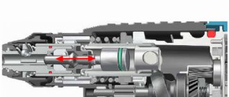
Wire release and ejection
The quality of the weld is affected by the length of the consumable material extending from the tip, as well as the size of the gap between the wire and the working surface. The discrepancy between the diameter of the wire and the size of its exit from the tip leads to excess spatter, metal burning, lack of fusion and warping.
Some designs of semi-automatic machines provide the ability to change the location of the burner tip relative to the nozzle. They are located at the same level, but the contact tube in relation to the nozzle can be extended or, conversely, recessed. The adjustment amplitude is 3.2 mm.
Short overhang is used to form welds on low alloy structural steel. As the distance increases in this case, the effectiveness of the protective gas cloud decreases. In order to increase the melting point, you can lengthen the flux wire slightly.
Release and overhang directly depend on the diameter of the filler wire:
Externally, it consists of the following elements:
1 Welding sleeve
2 Handle with button
The welding sleeve is a cable connecting the handle to a semi-automatic machine, inside of which there is:
1 Twisted channel for feeding welding wire from the feed mechanism to the torch handle.
2 Channel for supplying shielding gas to the welding zone.
3 Power cable.
At the other end of the sleeve there is a connector for connecting it to the feeding mechanism.
Such cables are supplied in lengths from 2.5 to 7 meters. This allows you to comfortably perform welding work at a remote distance from the semi-automatic machine. When using long hoses, there is a risk of wire jamming in the twisted channel.
Inside the nozzle there is:
1 Insulation ring
2 Electrode holder
3 Current carrying tip
4 Tip nozzle
The current-carrying tip is made of copper. This allows welding current to pass through without loss and excess heat to be removed when heated.
Burner device with sleeve
The diagram below clearly shows what elements they consist of:
There are also water-cooled burners. The diagram below shows one of them:
How to choose a burner and sleeve for a semi-automatic machine
Before making a choice, you first need to decide on the type and scope of work. If the work involves welding small components in small quantities, then purchasing an expensive torch will be unnecessary.
Therefore, you should pay attention to the following factors:
1. Maximum operating current of the welding machine;
2. Wire channel diameter;
3. Cooling method;
5. Connector for connection;
6. Strength and wear resistance of the burner with a sleeve
Maximum operating current of the welding machine
Selected depending on the maximum operating current of the power supply. If welding is performed with a current of 250A with a torch designed for a current of 200A, this can lead to overheating and melting of cables with wire channels inside the sleeve. If you do not plan to exceed the maximum permissible current, in such cases it can be used.
Wire channel diameter
There are two types of channels for wire passage: steel and Teflon. Each of them is used for a specific type of wire.
The steel channel is used for wires intended for welding carbon and alloy steels.
Teflon channels are used for aluminum wire.
There are different channel diameters - 0.6 - 3.0. The channel diameter is selected depending on the diameter of the welding material.
Burner cooling method
There are two types of cooling: non-cooled and water-cooled. To perform work at home and in small industries, where the welding process occurs intermittently, cooling is not necessary. If the welding process continues continuously for 10 - 15 minutes, then water cooling is required.
Torch for semi-automatic welding
The welder spends at least 40% of his total working time on preparatory activities, including replacing torch consumables and welding materials. Therefore, the speed and productivity of the work performed depends on the optimal selection of accessories and components for welding. The correct choice of a welding torch for semi-automatic welding will not only increase labor productivity, but also reduce the overall fatigue of the welder, providing a safer level when handling the device.
Gas burner for semi-automatic machine
When using semi-automatic MIG and MAG welding machines, selecting the optimal torch depends on the rated welding current, type of cooling and connector configuration. In any case, the length of the burner sleeve is from 3 to 5 meters, taking into account the tasks assigned.
Cooling of the device can be of two types:
- air;
- water (liquid).
Torches of the first type are used to work with currents up to 350 A (welding with short seams). Liquid cooling is important for welding long seams (regardless of the welding current). It is not difficult to purchase a high-quality burner for a semi-automatic machine in Moscow. Moreover, the range includes all types of devices and spare parts to ensure high-quality and safe operation.
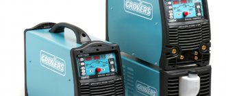
Review of AURORA burners for semi-automatic machines
The MIG-MAG welding torch can easily be called the welder’s main tool. The quality of execution of this device determines production costs, the convenience of the welder, and therefore his labor productivity. The group offers its customers a huge selection of welding torches for semi-automatic welding. Aurora torches will allow the welder to work with different wire diameters, from 0.6 to 1.6 mm. The devices are designed for a 60% duty cycle with maximum welding currents from 150 to 500A.
Welding torch device
When investing in a much-needed piece of welding equipment, a specialist takes the type of welding job performed and the capabilities of the semi-automatic machine as a basis. Moreover, when purchasing a burner, take into account its main components, which must be replaced over time.
Regardless of the manufacturer, the burner design includes:
- body with burner neck (gander) – rarely needs to be replaced;
- insulator - must be replaced either separately or with a gas nozzle;
- diffuser (holder) – after long-term operation requires replacement due to the adhesion of welding spatter;
- the nozzle is the most vulnerable place, susceptible to the negative effects of sticking pieces of metal;
- The current tip is the most worn part of the torch, which must be changed periodically.
Spare parts for semi-automatic burners
All parts for pin burners sooner or later wear out and become unusable. For welders, it is always important to have basic torch spare parts in your arsenal so that the welding process does not stop at the most inopportune moment.
Spare parts that should always be on hand:
- HDPG adapter;
- gas diffuser;
- tip holder;
- guide channel;
- nozzle;
- collet with accessories.
Repair of semi-automatic welding machines
The semi-automatic welding machine is designed on the basis of a welding inverter, the repair of which we discussed in the article “Repair of inverter welding machines.” Therefore, we recommend starting your acquaintance by reading the previous article.
To troubleshoot the problem, you can contact a workshop. If you feel strong and have the desire, then you can try to repair the welding machine with your own hands. We would like to warn you: if you do not have the appropriate experience and knowledge, then it is better (for the welder) and cheaper (for you) to take the device directly to a specialized workshop (see contacts in different cities here).
Inverter semi-automatic welding machine “Kontur-165”.
Preliminary inspection
Before disassembling the welding machine, check its settings. Poor operation of the device can be caused by the following reasons:
- electrode incorrectly selected in terms of material or diameter;
- incorrectly selected current value or voltage polarity;
- there may be no arc due to poor contact between the cable clamp and the part being welded;
- Temperature protection may well be triggered if the time of continuous operation of the welding machine is simply exceeded. You should just let it “rest” and cool down;
- Often the cause of failure is a cable break. Check its integrity.
If none of the above helped restore the functionality of the welder, then only then should you start repairing it.
Troubleshooting
Any repair begins with fault diagnosis. Malfunctions of this type of welder are divided into 2 groups:
- mechanical;
- electronic.
Checking the serviceability of the resistor.
Troubleshooting mechanical problems
Mechanical problems are caused by delayed wire feeding or excessive friction in the wire feed channel. The clamping mechanism should be checked and, if necessary, adjusted. If this operation does not give a positive result, then the canal is completely replaced.
It is recommended to install the new part simultaneously with removing the old one. This is done as follows:
- connect the end of the failed channel with the beginning of a new one;
- By pulling and removing the old channel, a new one is inserted in its place.
Checking modes with a tester.
Electronics Troubleshooting
It is recommended to check and troubleshoot in the following sequence:
- Check the fuses on the control board. If the fuses are working or you have replaced them, but the welder does not start working, then move on to the next point. Note that we will move on to each next point of the action plan proposed below after the negative results of the check for the current one;
- remove the control board and inspect it carefully. If you visually identify a faulty element (the housing has burst, the leads have melted, etc.), then replace it, put the board in place and check the functionality of the welder;
- carry out a “test” of all elements using a tester (ampere-voltmeter, multimeter, etc.). To prevent them from bridging each other, they should be desoldered and, after checking, replaced or replaced with serviceable ones. To avoid confusion, it is recommended to select the direction of the check (for example, left - right and top - bottom). In this case, the risk of missing any element will be minimized.
- After eliminating the malfunction, it is recommended to change the thermal paste on the radiators for cooling semiconductor elements.
If all the measures do not lead to a positive result, then the welder will have to be taken to the workshop.
In conclusion, we recommend watching a video about repairing the electronic part of a semi-automatic welding machine - an inverter. We wish you success!
Inverter setup
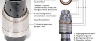
To ensure high-quality operation of a semiautomatic device with small dimensions, it is best to use toroidal type transformers. They have the highest efficiency.
The transformer for operation of the inverter is prepared as follows: it must be wrapped with a copper strip (40 mm wide, 30 mm thick), protected with thermal paper, of the required length. The secondary winding is made of 3 layers of sheet metal, insulated from each other. To do this, you can use fluoroplastic tape. The ends of the secondary winding at the output must be soldered. In order for such a transformer to operate smoothly and not overheat, it is necessary to install a fan.
Transformer winding diagram
Work on setting up the inverter begins with de-energizing the power section. Rectifiers (input and output) and power switches must have radiators for cooling. Where the radiator is located, which heats up the most during operation, it is necessary to provide a temperature sensor (its readings during operation should not exceed 75 0 C). After these changes, the power section is connected to the control unit. When switched on. The network indicator should light up. You need to check the pulses using an oscilloscope. They should be rectangular.