Semi-automatic device
The structure of a semi-automatic machine is the first thing you need to study if you want to assemble your own machine.
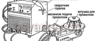
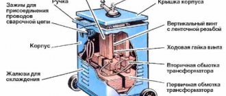
A standard semi-automatic machine consists of two parts (or two blocks): power and feed. The feed part is simply a feed device for semi-automatic welding. But, let's take a closer look at the semi-automatic device.
The power part, also known as the power unit, is essentially an inverter. The inverter acts as a current source. Everything is simple here. But the feeding part is a separate, plug-in feeding mechanism. The feed mechanism is used to feed the wire. The wire is sold in reels and the reel is inserted directly into the feeder. Its end exits through the burner nozzle.
Of course, you don't have to use a feed mechanism to perform semi-automatic welding. The wire can also be fed manually. But this is extremely inconvenient, and in this case the whole essence of semi-automatic technology is lost.
That's all the components. This, of course, is not enough to make a semi-automatic welding machine on your own. You will also have to buy additional parts, but they depend on the type of inverter you have and the method by which you will convert it into a semi-automatic machine. Don’t forget about the components (burner, hose, correctly selected nozzle, etc.).
Features of the node operation
The main feature of the semi-automatic wire feed mechanism is that its operation does not depend on the operation of the welding machine itself . There are two types of construction - stationary and portable. In the first case, the device is installed directly on the welding unit and moves only with it. In the second case, the device is more mobile, since it is considered a separate unit.
The disadvantage of autonomous devices is the technological complexity of the design, which requires specific maintenance, along with other welding equipment. Without special operating skills, servicing the unit will be problematic.
The mobile scheme has long been implemented by the domestic welding equipment plant SELMA. Feeding mechanisms are always sold separately from semi-automatic machines.
Principle of operation
The operating principle of the semi-automatic device is simple. It will be clear even to a beginner, so study this information carefully. It will be useful for assembling a homemade device.
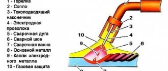
So, it all starts with feeding the torch into the welding zone. The torch combines two devices: from its nozzle it supplies protective gas and wire simultaneously. The welder regulates the amount of gas manually, but the wire is fed in a semi-automatic mode (hence the name “semi-automatic”). That is why the welder always has only one hand occupied during the process. The one holding the burner.
As we have already said, gas is supplied to the welding zone simultaneously with the wire. An electric discharge is formed in the mixture of gases between the end of the wire and the metal surface, due to which the workpiece and the wire itself melt. Molten metal is mixed with molten wire. Next, you can form the seam.
In this case, wire is necessary and without it welding is simply impossible. Gas is also needed; it protects the weld pool from oxygen coming from outside. But if you do not have the opportunity to use gas, you can take a special cored wire and cook only with it.
General information
A semi-automatic welding machine is a device designed for joining metals using electric arc welding. The difference from a classic welding machine is that instead of the usual tungsten electrodes, melting wire is used. It is wound on a special reel and automatically unwinds as the work process progresses. E42 electrodes are also used for this type of welding.
Thus, there is a constant supply of electrode to the weld pool. The welding itself is carried out manually by a welder who can regulate the speed of unwinding the wire spool.
Semi-automatic devices are divided depending on the degree of protection of the welding zone, namely:
- Devices intended for welding with flux. In this case, the flux enters as an additive into the wire itself. This is a fairly expensive method and is rarely used in homemade devices.
- Devices using a gas environment. The most popular and widespread method among welders.
- Semi-automatic machines working with special flux-cored wire. This option is usually used in conjunction with gas protection.
A semi-automatic machine best reveals its advantages when you need to carefully, beautifully and accurately connect thin steel parts. The connection will be reliable with a wide variety of steel grades, such as alloy, low-carbon, stainless steel.
Semiautomatic from inverter
There are several ways to make a working semi-automatic device from an inverter. We will list the most interesting, in our opinion. You can implement them at home with basic knowledge of electrical engineering.
Method No. 1
To make an inverter semi-automatic welding machine with your own hands, you will need a “donor”. Without it, it’s simply not possible to make a semi-automatic machine. As a “donor”, take not the weakest inverter for MMA welding. It must be operational and perform normal welding operations without any problems.
You need to change the current-voltage characteristics of the inverter you have chosen so that it can operate in semi-automatic welding mode. You can use a PWM controller for this. However, this option is very labor-intensive and is not suitable for those who are not strong in electrical engineering.
Therefore, in order to assemble a semi-automatic welding machine from an inverter with your own hands, we recommend making a choke. A choke from a fluorescent lamp is suitable for this. And after the throttle you need to take the feedback voltage. Watch the video below, which explains the essence of this method in detail. There is also a clear diagram in the video.
Method No. 2
The second method is extremely simple and is suitable for those who have a certain inverter welding. The fact is that there are inverters on sale that can switch to a mode with a rigid change in the current-voltage characteristic. If you are the owner of just such an inverter, then you can only be happy for yourself. To turn such a device into a semi-automatic machine, you just need to purchase an external feed mechanism.
The mechanism must include all the necessary cables and connectors. You just need to easily connect the welding wire feeder to the welding inverter and you can start welding. We can assume that in this case the feed mechanism works as an attachment to the inverter for semi-automatic welding. Watch the video below, where the author talks about his inverter, to which he connected the feeder.
Method No. 3
The last method of converting from a welding inverter into a semi-automatic machine with your own hands will require some knowledge and skills. In this case, you will also need a donor inverter. Please note that not every device will work. You need an inverter with ZX-7 layout. It must have a shunt at the output, and there must be a current transformer at the “primary”. It’s even better if the device doesn’t have any additional functions like hot start or arc force.
You also need to change the current-voltage characteristics, and also set the current rise setting. Further actions directly depend on the circuit of your inverter. So don’t be lazy to find topics on various forums dedicated to converting an inverter into a semi-automatic machine. Watch the video below with a test of such a homemade device.
Feeder
Let's take a closer look at what the feeding mechanism consists of:
- Welding sleeve. It is a flexible frame hose covered with multilayer rubber to protect and insulate the power cable. Inside there is a special steel spiral channel for feeding the welding wire to the welding site. The hose also to protect the weld pool from the environment. Near the welding torch there is a button to turn on the wire and gas feed mechanism.
- Wire feed mechanism. Ensures uninterrupted wire feed through the welding hose. It consists of a direct or alternating current electric motor, a clamping device for pressing the rollers using screw clamps with a certain force.
- Device for installing a cassette with welding wire. It is located near the feed mechanism and is designed to provide the welding arc with filler material for a long time. The cassette can be positioned both vertically and horizontally relative to the feeding mechanism. The cassette is secured using a special nut or clamps.
- Control unit. It is used to adjust the wire feed. The adjustment can be electronic using a rheostat or more coarse thanks to interchangeable gears. Modern ones are equipped with digital displays, on which you can accurately set the welding speed and thereby ensure better seam formation.
The main advantages over welding with electrodes are a faster welding process, there is no need to change the electrode often, and better control over the welding process. The disadvantages are the fear of drafts and strong winds (possible formation of pores), and the connection to the source of protective gas (cylinder, ramp).
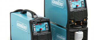
Popular models
Let's look at the devices that are in greatest demand.
LF-37/38
Modern device made in the USA. A high degree of protection from dust and moisture allows welding in difficult conditions . Operation with both flux and filler wire on reels with a diameter of 0.6-1.6 mm is possible. There is a gas flow meter and an indicator panel. Adapted for connecting liquid cooling. Multilingual interface. Operating voltage – 42 V. Weight – 16 kg.
MSF-57
Modular wire feeder made in Finland. The two-layer housing is made of high-strength plastic that is resistant to mechanical damage. The device is equipped with a modern DuraTorque 4x4 feed mechanism . Capable of operating with currents up to 520 A. The on-time at a current of 440 A is 100%. Wire cross-section – 0.6-2.4 mm. Operating voltage – 50 V. Weight – 12.5 kg.
Forsazh-MPC02
The mechanism is from a domestic manufacturer. It is highly reliable at an affordable price. A wide range of feed speed adjustment allows you to select the optimal welding mode . The switching duration at a current of 400 A is 100%. It is possible to perform work in MMA mode. Adjustment of gas purging time and arc stretching. Wire cross-section – 0.6-2.0 mm. Digital indication of parameters. Weight – 12.5 kg.
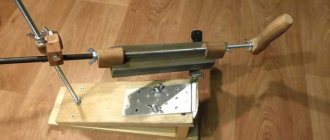
Structure
The design of the simplest welding wire feeder contains the following elements :
- Stationary roller . Has a groove for wire. It rotates only around its own axis. A removable element that is installed when the diameter of the electrode changes.
- Guide tubes . Set the motion vector for the filler material.
- Movable roller . It has the same characteristics as the element described above, but performs the function of adjusting the pressure on the passing wire.
- Clamping mechanism . Includes spring connected bolts and lever. The number of turns adjusts the degree of compression, and the spring prevents the material from sagging.
- Motor with reduction gear . Performs drive functions, transmitting torque to a stationary roller. Transmission is usually carried out by a gear mechanism. Automation selects the required voltage in the system to regulate the speed of movement.
Operating principle
The operating principle of this device is based on the transmission of a moment of force to a stationary roller, which, depending on the design of the mechanism, pulls or pushes the wire through the guides. Smooth running is ensured by the clamping mechanism.
For thin wire, two rollers are used - a pressure roller and a drive roller. With a cross-sectional diameter greater than 1 mm, the number of rollers is doubled.
Some manufacturers, in order to increase service life, produce models with replaceable bushings that are mounted in guide tubes.