Technical data of our semi-automatic welding machine:
Supply voltage: 220 V Power consumption: no more than 3 kVA Operating mode: intermittent Operating voltage regulation: stepwise from 19 V to 26 V Welding wire feed speed: 0-7 m/min Diameter wire: 0.8 mm Welding current value: PV 40% - 160 A, PV 100% - 80 A Welding current control limit: 30 A - 160 A
A total of six such devices have been made since 2003. The device shown in the photo below has been in service since 2003 in a car service center and has never been repaired.
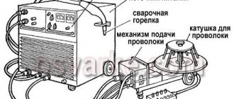
↑ Appearance of semi-automatic welding machine
At all
Front view
Back view
Left view
A standard 5kg coil of wire with a diameter of 0.8mm is used as welding wire.
A 180 A welding torch along with a Euro connector was purchased at a welding equipment store.
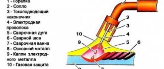
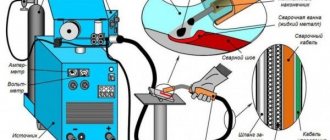
↑ Diagram and details of the welder
Due to the fact that the semi-automatic circuit was analyzed from such devices as PDG-125, PDG-160, PDG-201 and MIG-180, the circuit diagram differs from the circuit board, since the circuit emerged on the fly during the assembly process. Therefore, it is better to stick to the wiring diagram. On the printed circuit board, all points and parts are marked (open in Sprint and hover your mouse).
Signet, see drawing in the archive
Installation view
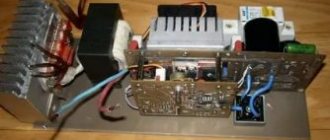
Control board
A single-phase 16A type AE circuit breaker is used as a power and protection switch. SA1 - welding mode switch type PKU-3-12-2037 with 5 positions.
Resistors R3, R4 are PEV-25, but they don’t have to be installed (I don’t have them). They are designed to quickly discharge choke capacitors.
Now for capacitor C7. Paired with a choke, it ensures combustion stabilization and arc maintenance. Its minimum capacity should be at least 20,000 microfarads, optimal 30,000 microfarads. Several types of capacitors with smaller dimensions and higher capacity were tried, for example CapXon, Misuda, but they did not prove to be reliable and burned out.
As a result, Soviet capacitors were used, which still work to this day, K50-18 at 10,000 uF x 50V, three in parallel.
Power thyristors for 200A are taken with a good margin. You can install it at 160 A, but they will work at the limit, and you will need to use good radiators and fans. The used B200s stand on a small aluminum plate.
Relay K1 type RP21 for 24V, variable resistor R10 wirewound type PPB.
When you press the SB1 button on the burner, voltage is supplied to the control circuit. Relay K1 is activated, thereby, through contacts K1-1, voltage is supplied to the electromagnetic valve EM1 for acid supply, and K1-2 - to the power supply circuit of the wire drawing motor, and K1-3 - to open the power thyristors.
Switch SA1 sets the operating voltage in the range from 19 to 26 Volts (taking into account the addition of 3 turns per arm up to 30 Volts). Resistor R10 regulates the supply of welding wire and changes the welding current from 30A to 160A.
When setting up, resistor R12 is selected in such a way that when R10 is turned to minimum speed, the engine still continues to rotate and does not stand still.
When you release the SB1 button on the torch, the relay releases, the motor stops and the thyristors close, the solenoid valve, due to the charge of capacitor C2, still remains open, supplying acid to the welding zone.
When the thyristors are closed, the arc voltage disappears, but due to the inductor and capacitors C7, the voltage is removed smoothly, preventing the welding wire from sticking in the welding zone.
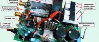
Self-refinement of the welding inverter
Rectifier and filter protection unit - consists of RL1, R4. Prevents the appearance of large charging currents when the inverter is connected to the network. When the power is turned on, voltage is supplied to rectifier PD1 through a powerful resistor R4, at this moment capacitors C21, C22, C27 are smoothly charged. Rectifier bridge and filter - consists of PD1, which converts alternating voltage into pulsating, filter C21, C22, C27 - smoothes out ripples of the rectified voltage.
They convert the filtered voltage into high-frequency rectangular pulses, which are supplied to the power transformer. Current transformer - T2, controls the current strength in the primary winding of the power transformer, the signal from the transformer goes to the control unit.
Your cart
Power transformer - T3, converts the voltage and current from the inverter into the voltage and current required for welding. It also provides galvanic isolation from the supply network. Welding voltage rectifier - D32, D33, D D32 - rectifies the pulse voltage and also serves to limit the saturation of the transformer core. D33 and D34 - rectify the self-induction voltage of the power transformer after the inductor L1, at moments when the IGBT transistors are closed.
Choke L1 - suppresses rectified voltage ripple. Thermal protection of the power transformer - thermal sensor ST1 is closed in the normal state. As soon as the storage capacitors are charged, the converter starts working, voltage appears on the additional winding, which is rectified and supplied to the blower fan and relay.
In recent years, the inverter has become one of the most popular welding machines. It is now used by many professionals and ordinary people. In some cases, such equipment has to be modified. The modification of the welding transformer can be entrusted to professionals, or you can do it yourself.
The relay turns on, closes resistor R4 with its contacts and the device returns to normal operation. Let's move on to the control unit: Larger The control unit consists of the following components: 1. Isolating transformer T1 produces two signals, galvanically separated from each other. Isolation transformer control driver Q4, D20, D22, D24 - amplifies the signal coming from the duty cycle shaper pulse generator and supplies it to the primary winding of the isolation transformer.
This controller provides the generation of control pulses for the operation of the inverter using IGBT transistors. This microcircuit also regulates the welding current and protects against excess current in the primary winding of the power transformer. At the same time, the capacity of high-voltage capacitors increases by about 20 times, and low-voltage capacitors - by a factor of 20. In addition, this entire structure is treated with chemicals to achieve the required parameters.
Electrolytic capacitors have a rather complex structure, which makes them difficult to manufacture and operate.
Welding machine design
The characteristics of capacitors can vary greatly under different operating modes and operating climatic conditions. With increasing frequency and temperature, the capacitance of the capacitor and ESR decreases.
The enormous interest and peak of popularity that has increased over the last decade in new designs of welding machines operating on the principle of inverters is due to the following main reasons: These advantages became possible thanks to a change in the approach to the technology of creating a welding arc on an electrode through the introduction of the latest advances in microprocessor technology. How welding inverters work. They are powered by V 50 Hz electricity, which comes from a regular electrical outlet.
As the temperature decreases, the capacitance also drops, and the ESR can increase up to times, which, in turn, reduces the maximum permissible ripple current of the capacitor. The reliability of pulse and input network filter capacitors, first of all, depends on their maximum permissible ripple current.
Flowing ripple currents can heat up the capacitor, which causes its early failure. In inverters, the main purposes of electrolytic capacitors are to increase the voltage in the input rectifier and smooth out possible ripples.
Significant problems in the operation of inverters are created by large currents through transistors, high requirements for the shape of control pulses, which implies the use of powerful drivers to control power switches, high requirements for the installation of power circuits, and large pulse currents.
When buying an inverter welding machine for work in a garage or in a country house, the first thought is - wow, now I can cook everything! You do not need a welding diploma; the device is designed for users without special education. Handling welding has become easier and more comfortable. The main thing is to understand the principle of operation and first aid in case of difficulties and breakdowns.
All this largely depends on the quality factor of the input filter capacitors, so for inverter welding machines you need to carefully select the parameters of electrolytic capacitors. Thus, in the preliminary rectification unit of a welding inverter, the most critical element is the filtering electrolytic capacitor installed after the diode bridge.
It is recommended to install the capacitor in close proximity to the IGBT and diodes, which eliminates the influence of the inductance of the wires connecting the device to the power source on the operation of the inverter.
Also, installing capacitors near consumers reduces the internal resistance to alternating current of the power supply, which prevents excitation of the amplifier stages. Typically, the filter capacitor in full-wave converters is selected so that the rectified voltage ripple does not exceed 5...10 V.
It should also be taken into account that the voltage on the filter capacitors will be 1.41 times greater than at the output of the diode bridge. Thus, if after the diode bridge we get V of a pulsating voltage, then there will already be V of a constant voltage on the capacitors.
Typically, the operating voltage in the network is limited to V, therefore, the voltage at the filter output will be V.
In rare cases, the mains voltage may rise even higher, so capacitors should be selected for an operating voltage of at least V. Capacitors may have additional heating due to high operating currents.
Input capacitors for smoothing out rectified voltage ripples are selected with a capacitance of ... µF depending on the power of the device.
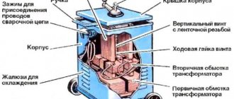
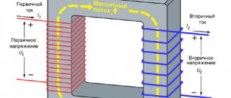
↑ Winding up the welding transformer
We take the OSM-1 transformer (1 kW), disassemble it, put the iron aside, having previously marked it. We make a new coil frame from PCB 2 mm thick (the original frame is too weak). Cheek size 147×106mm. Size of other parts: 2 pcs. 130×70mm and 2 pcs. 87x89mm. We cut out a window measuring 87x51.5 mm in the cheeks. The coil frame is ready. We are looking for a winding wire with a diameter of 1.8 mm, preferably in reinforced fiberglass insulation. I took such a wire from the stator coils of a diesel generator). You can also use ordinary enamel wire such as PETV, PEV, etc.
Fiberglass - in my opinion, the best insulation is obtained. We begin winding - primary.
The primary contains 164 + 15 + 15 + 15 + 15 turns. Between the layers we make insulation from thin fiberglass. Lay the wire as tightly as possible, otherwise it won’t fit, but I usually didn’t have any problems with this. I took fiberglass from the remains of the same diesel generator. That's it, the primary is ready.
We continue to wind - secondary.
We take an aluminum busbar in glass insulation measuring 2.8x4.75 mm (can be purchased from wrappers). You need about 8 m, but it is better to have a small margin. We begin to wind, laying it as tightly as possible, we wind 19 turns, then we make a loop for the M6 bolt, and again 19 turns. We make the beginnings and ends 30 cm each, for further installation. Here is a small digression, personally, for me to weld large parts at such a voltage, the current was not enough; during operation, I rewound the secondary winding, adding 3 turns per arm, in total I got 22+22. The winding fits snugly, so if you wind it carefully, everything should work out. If you use an enamel wire as a primary material, then you must impregnate it with varnish; I kept the coil in the varnish for 6 hours.
We assemble the transformer, plug it into an outlet and measure the no-load current of about 0.5 A, the voltage on the secondary is from 19 to 26 Volts. If everything is so, then the transformer can be put aside; we no longer need it for now.
Instead of OSM-1 for a power transformer, you can take 4 pieces of TS-270, although the dimensions are slightly different, and I only made 1 welding machine on it, so I don’t remember the data for winding, but it can be calculated.
tarakanmex › Blog › Review of semi-automatic welding machine Do-it-yourself. The final.
At the moment, inverter MMA welding machines (for welding with stick electrodes) are very common; they produce direct current, weigh little and have good efficiency compared to transformers, and have quite affordable prices. There are also inverter semi-automatic MIG/MAG machines, they have the same advantages except for one thing - the price, based on this, I thought about how to make a semi-automatic machine from a regular inverter welder. The beginning of a project to build a semi-automatic welding machine, or rather an attachment to an inverter, so that the inverter can be used in semi-automatic mode. In our case, a good welding inverter is BRIMA ARC-250
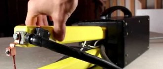
↑ We will twist the throttle
We take an OSM-0.4 transformer (400W), take an enamel wire with a diameter of at least 1.5 mm (I have 1.8).
We wind 2 layers with insulation between the layers, lay them tightly. Next we take an aluminum tire 2.8x4.75 mm. and wind 24 turns, making the free ends of the bus 30 cm long. We assemble the core with a gap of 1 mm (lay in pieces of PCB). The inductor can also be wound on iron from a color tube TV like TS-270. Only one coil is placed on it. We still have one more transformer to power the control circuit (I took a ready-made one). It should produce 24 volts at a current of about 6A.
Finishing up the budget semi-automatic
There are a lot of inexpensive semi-automatic welding machines on the market that will never work properly because they were made incorrectly from the start. Let's try to fix this on a welding machine that has already fallen into disrepair.
I came across a Chinese Vita semi-automatic welding machine (from now on I will simply call it PA), in which the power transformer burned out; my friends just asked me to repair it.
They complained that when they were still working, it was impossible for them to cook anything, there were strong splashes, crackling, etc. So I decided to bring it to a conclusion, and at the same time share my experience, maybe it will be useful to someone. Upon first inspection, I realized that the transformer for the PA was wound incorrectly, since the primary and secondary windings were wound separately; the photo shows that only the secondary remained, and the primary was wound next to it (that’s how the transformer was brought to me).
This means that such a transformer has a steeply falling current-voltage characteristic (volt-ampere characteristic) and is suitable for arc welding, but not for PA. For Pa, you need a transformer with a rigid current-voltage characteristic, and for this, the secondary winding of the transformer must be wound on top of the primary winding.
In order to start rewinding the transformer, you need to carefully unwind the secondary winding without damaging the insulation, and cut off the partition separating the two windings.
For the primary winding I will use 2 mm thick enamel copper wire; for complete rewinding we will need 3.1 kg of copper wire, or 115 meters. We wind turn to turn from one side to the other and back. We need to wind 234 turns - that’s 7 layers, after winding we make a tap.
Then we wind 39 turns, make another branch, 25 turns - a branch, and 14 turns - a branch.
We insulate the primary winding and taps with fabric tape. Next we wind the secondary winding with the same wire that we wound earlier. We wind tightly 36 turns, with a shank of 20 mm2, approximately 17 meters.
The transformer is ready, now let's work on the choke. The throttle is an equally important part in the PA, without which it will not work normally. It was made incorrectly because there is no gap between the two parts of the magnetic circuit. I will wind the choke on iron from the TS-270 transformer. We disassemble the transformer and take only the magnetic circuit from it. We wind a wire of the same cross-section as on the secondary winding of the transformer on one bend of the magnetic circuit, or on two, connecting the ends in series, as you like. The most important thing in the inductor is the non-magnetic gap, which should be between the two halves of the magnetic circuit; this is achieved by PCB inserts. The thickness of the gasket ranges from 1.5 to 2 mm, and is determined experimentally for each case separately.
For a more stable arc burning, capacitors with a capacity of 20,000 to 40,000 μF must be placed in the circuit and the capacitor voltage should be from 50 volts. Schematically it all looks like this.
In order for your PA to work normally, it will be enough to do the above steps.
And for those who are annoyed by the direct current on the burner, you need to install a 160-200 ampere thyristor in the circuit, see how to do this in the video.
Thank you all for your attention -)
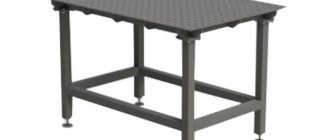
↑ Case and mechanics
We've sorted out the trances, let's move on to the body. The drawings do not show 20 mm flanges. We weld the corners, all iron is 1.5 mm. The base of the mechanism is made of stainless steel.
For detailed housing drawings, see the appendix.
Motor M is used from a VAZ-2101 windshield wiper. The limit switch for returning to the extreme position has been removed.
In the bobbin holder, a spring is used to create braking force, the first one that comes to hand. The braking effect is increased by compressing the spring (i.e. tightening the nut).