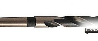
A centering drill belongs to the category of combined type tools: it can be used to create holes in parts made of various materials (cast iron, ordinary and alloy steels, metal-ceramic alloys based on bronze and iron). With the help of such drills, as their name implies, holes are created for further processing of workpieces when they are fixed in the centers of metal-cutting equipment.
Centering the future hole on a lathe
Production and main parameters
A drill, called a centering drill, is a professional tool used primarily by large and medium-sized enterprises that have lathes and milling machines in their arsenal. Its production is regulated by a document such as GOST 14952-75. Using centering drills, holes are made whose axis is perpendicular to the surface of the workpiece.
It should be noted that no other metal processing tool allows one to achieve such precision in the formation of holes, as well as their high quality.
Variety of types and sizes of centering drills
When making holes using a center drill, the likelihood of accumulating errors during processing is reduced to zero. Many other types of drills do not allow drills to produce holes whose dimensions and location strictly correspond to the drawing. GOST 14952-75 defines a wide range of drill diameters of this type: from 0.5 to 10 mm. This regulatory document also identifies 4 main types of centering drills:
- A - for the formation of centering holes, the taper of the sides of which is 60 degrees (such drills do not have a cutting surface that forms the so-called safety cone);
- B – for making centering holes with a safety cone on the working part (the angle of rotation of its sides is 120 degrees);
- C – to create centering holes without a safety cone with a rotation angle of 75 degrees;
- R – for the formation of centering holes, the forming surfaces of which have an arcuate configuration.
Dimensions and shapes of center holes
Drills from each of the categories presented above are available in two versions: with a main cutting tip diameter of up to eight tenths of a millimeter (first type) and more than eight tenths of a millimeter (second type). When using a centering tool of the first type, the roughness of the walls of the formed center hole is less than when using a tool with a tip diameter greater than eight tenths of a millimeter. Thus, the choice of a drill of one type or another is mainly influenced by the requirements for the degree of roughness of the walls of the hole being formed.
You can determine what type of tool you are holding in your hands by its marking, the rules of which are also established by GOST 14952-75. Thus, the marking of centering drills with the same geometric parameters, but of different types, looks like this:
- drills of category “A”, the diameter of which is 1 mm: the first type of execution - 2317-0101, the second type - 2317-0001.
- drills of category “B”, the diameter of which is also 1 mm: the first type - 2317-0113, the second - 2317-0012.
- category “C” tool with a diameter of 1 mm: the first type – 2317-0124, the second – 2317-0022.
- drills of category “R” of the same diameter: the first type – 2317-0129, the second – 2317-0027.
High speed steel center drill
All geometric parameters of centering drills of different types are determined by GOST 14952-75, in which they are presented in the corresponding tables.
GOST 14952-75 Combined centering drills. Specifications
Center holes
CENTER HOLES WITH CONE ANGLE 60o (GOST 14034-74) * Size for reference
| D | d | d1 | d2 | d3, to H14 | l, no less | l1 | l2, to H12 | l3, no less | |
| nominal | prev off | ||||||||
| 2,0 | (0,5) | 1,6 | — | — | 0,8 | 0,48 | H11 | — | — |
| 2,5 | (0,63) | 1,32 | — | — | 0,9 | 0,60 | — | — | |
| 3 | (0,8) | 1,70 | 2,50 | — | 1,1 | 0,78 | 1,02 | — | |
| 4 | 1,0 | 2,12 | 3,15 | — | 1,3 | 0,97 | 1,27 | — | |
| 5 | (1,25) | 2,65 | 4,00 | — | 1,6 | 1,21 | H12 | 1,60 | — |
| 6 | 1,6 | 3,35 | 5,00 | — | 2,0 | 1,52 | 1,99 | — | |
| 10 | 2,0 | 4,25 | 6,30 | 7,0 | 2,5 | 1,95 | 2,54 | 0,6 | |
| 14 | 2,5 | 5,30 | 8,00 | 9,0 | 3,1 | 2,42 | 3,20 | 0,8 | |
| 20 | 3,15 | 3,70 | 10,0 | 12,0 | 3,9 | 3,07 | 4,03 | 0,9 | |
| 30 | 4 | 8,50 | 12,50 | 16,0 | 5,0 | 3,90 | 5,06 | 1,2 | |
| 40 | (5) | 10,60 | 16,0 | 20,0 | 6,3 | 4,85 | 6,41 | 1,6 | |
| 60 | 6,3 | 13,20 | 18,0 | 25,0 | 8,0 | 5,98 | 7,36 | 1,8 | |
| 80 | (8) | 17,0 | 22,40 | 32,0 | 10,1 | 7,79 | 9,35 | 2,0 | |
| 100 | 10 | 21,20 | 28,00 | 36,0 | 12,8 | 9,70 | 11,66 | 2,5 | |
| 120 | 12 | 25,40 | 33,0 | — | 14,6 | 11,6 | 13,80 | — | |
| 160 | 16 | 33,90 | 42,50 | — | 19,2 | 15,50 | 18,00 | — | |
| 240 | 20 | 42,40 | 51,60 | — | 25,0 | 19,40 | 22,00 | — | |
| 360 | 25 | 53,00 | 63,30 | — | 32,0 | 24,0 | 27,0 | — | |
Notes:
1. Dimensions enclosed in brackets are not recommended. 2. Dimensions D are recommended.
An example of the designation of a center hole of shape A with a diameter of d = 1 mm:
Hole. center. A1 GOST 14034-74 CENTER HOLES WITH CONE ANGLE 75o (GOST 14034-74) * Size for reference
| D | d | d1 | d2 | l, no less | l1, to H17 | l2, according to H17 |
| 120 | 8 | 23,3 | 30,2 | 10 | 10 | 12,0 |
| 180 | 12 | 36,6 | 45,4 | 15 | 16 | 18,5 |
| 260 | 20 | 60,0 | 70,3 | 22 | 26 | 29,0 |
| 360 | 30 | 91,4 | 105,0 | 32 | 40 | 44,0 |
| 500 | 40 | 120,0 | 137,0 | 43 | 52 | 57,0 |
| 800 | 50 | 150,0 | 170,5 | 52 | 65 | 71,0 |
| 1200 | 63 | 186,0 | 213,7 | 65 | 80 | 88,0 |
Note:
Sizes D are recommended.
An example of the designation of the center hole of a form C with a diameter of d = 8 mm:
Hole. center. C8 GOST 14034-74 CENTER HOLE WITH ARC-SHAPED FORMER (GOST 14034-74)
| D | d | d1 | l, no less | r | |
| least | greatest | ||||
| 2 | (0,5) | 1,30 | 1,3 | 1,30 | 1,60 |
| 2,5 | (0,63) | 1,50 | 1,5 | 1,60 | 2,00 |
| 3 | (0,8) | 1,70 | 1,9 | 2,00 | 2,50 |
| 4 | 1 | 2,12 | 2,3 | 2,50 | 3,15 |
| 5 | (1,25) | 2,65 | 2,8 | 3,15 | 4,00 |
| 6 | 1,6 | 3,35 | 3,5 | 4,00 | 5,00 |
| 10 | 2 | 4,25 | 4,4 | 5,00 | 6,30 |
| 14 | 2,5 | 5,30 | 5,5 | 6,30 | 8,00 |
| 20 | 3,15 | 6,70 | 7,0 | 8,00 | 10,00 |
| 30 | 4 | 8,50 | 8,9 | 10,00 | 12,50 |
| 40 | (5) | 10,60 | 11,2 | 12,50 | 16,00 |
| 60 | 6,3 | 13,20 | 14,0 | 16,00 | 20,00 |
| 80 | (8) | 17,00 | 17,9 | 20,00 | 25,00 |
| 100 | 10 | 21,20 | 22,5 | 25,00 | 31,50 |
Notes:
1. Dimensions enclosed in brackets are not recommended. 2. Dimensions D are recommended.
An example of the designation of a center hole of shape R with a diameter of d = 1 mm:
Hole. center. R1 GOST 14034-74 CENTER HOLES WITH METRIC THREAD (GOST 14034-74) * Dimensions for reference
| D is for shape | d | d1, H14 | d2 | d3 | l, no less | l1, H15 | l2, no more | l3, H15 | α | |
| F | H | |||||||||
| 8 | — | M3 | 3,2 | 5 | — | 2,8 | 1,56 | — | — | 60° |
| 10 | 16 | M4 | 4,3 | 6,5 | 8,2 | 3,5 | 1,90 | 4,0 | 2,4 | |
| 12,5 | 20 | M5 | 5,3 | 8,0 | 11,4 | 4,5 | 2,30 | 5,5 | 3,3 | |
| 16 | 25 | M6 | 6,4 | 10,0 | 13,3 | 5,5 | 3,00 | 6,5 | 4,0 | |
| 20 | 32 | M8 | 8,4 | 12,5 | 16,0 | 7,0 | 3,50 | 8,0 | 4,5 | |
| 25 | 40 | M10 | 11,0 | 15,6 | 19,8 | 9,0 | 4,00 | 10,2 | 5,2 | |
| 32 | 50 | M12 | 13,0 | 18,0 | 22,0 | 10,0 | 4,30 | 11,2 | 5,5 | |
| 40 | 63 | M16 | 17,0 | 22,8 | 28,7 | 11,0 | 5,00 | 12,5 | 6,5 | |
| 63 | 80 | M20 | 21,0 | 28,0 | 33,0 | 12,5 | 6,00 | 14,0 | 7,5 | |
| 100 | M24 | 25,0 | 36,0 | 43,0 | 14,0 | 9,50 | 16,0 | 11,5 | ||
| 160 | M30 | 31,0 | 44,8 | 51,8 | 18,0 | 12,00 | 20,0 | 14,0 | ||
| 250 | M36 | 37,5 | 53,0 | 60,0 | 20,0 | 13,5 | 22,0 | 15,5 | ||
| 400 | M42 | 43,5 | 59,7 | 70,5 | 22,0 | 14,0 | 25,0 | 17,0 | ||
| 630 | M48 | 49,5 | 74,0 | 88,0 | 24,0 | 16,0 | 28,0 | 20,0 | 75° | |
| 900 | M56 | 58,0 | 85,6 | 99,5 | 27,0 | 18,0 | 31,0 | 22,0 | ||
| St. 1200 | M64 | 66,0 | 95,0 | 112,5 | 29,0 | 19,0 | 34,0 | 24,0 | ||
| M72x6 | 74,0 | 104,7 | 122,0 | 31,0 | 20,0 | 36,0 | 25,0 | |||
| M80x6 | 82,0 | 115,7 | 133,0 | 34,0 | 22,0 | 39,0 | 27,0 | |||
| M100x6 | 102,0 | 140,0 | 160,0 | 36,0 | 24,0 | 42,0 | 30,0 | |||
Notes:
1. Dimensions D are recommended. 2. Forms F and H should not be used for cutting and accessory tools with 1:10, 1:7, 7:24, metric and Morse taper shanks.
An example of the designation of a center hole of shape F with a thread diameter d = M3 mm:
Hole. center. F M3 GOST 14034-74 CENTER HOLES WITH METRIC THREAD (GOST 14034-74) recommended * Dimensions for reference
| Designation of cones | d | d1, to H14 | d2 | d3, Н14 | L, not less | l | l1 | l2, no less | ||||
| GOST 25557-2006 | GOST 9953-82 | GOST 7343-72 | GOST 24644-41 | |||||||||
| Metric | Morse | |||||||||||
| — | 1 | B12 | — | — | M6 | 6,4 | 8,0 | 8,5 | 16 | 3,5 | 1,53 | — |
| 2 | B18 | M10 | 10,5 | 12,5 | 13,2 | 24 | 4,5 | 1,90 | — | |||
| 3 | B24 | 30 | M12 | 13,0 | 15,0 | 17,0 | 28 | 6,0 | 2,30 | 0,6 | ||
| 4 | B32 | 40 | M16 | 17,0 | 20,0 | 22,0 | 32 | 8,0 | 3,20 | — | ||
| 5 | B45 | 80 | 45 | M20 | 21,0 | 26,0 | 30,0 | 40 | 10,0 | 5,50 | 1,1 | |
| 90 | ||||||||||||
| 6 | — | — | 50; 55 | M24 | 25,0 | 31,0 | 36,0 | 50 | 11,0 | 6,60 | 1,4 | |
| 80 | — | 100 | 60 | M30 | 31,0 | 38,0 | 45,0 | 65 | 14,0 | 8,0 | 2,0 | |
| (110) | ||||||||||||
| 120 | ||||||||||||
| 140 | ||||||||||||
| 100 | 160 | 65 | M36 | 37,0 | 45,0 | 52,0 | 80 | 15,0 | 9,0 | |||
| 120 | (180) | |||||||||||
| — | 200 | |||||||||||
| — | — | 70 | M36* | 50,0 | 60,0 | 68,0 | 100 | 18,0 | 11,0 | 2,3 | ||
| 160 | M48 | |||||||||||
| 200 | ||||||||||||
Note:
* Thread diameter M36 only for cone No. 70 GOST 24644-81.
APPLICATION OF CENTER HOLE FORMS Form A
- in cases where after processing there is no need for center holes, and in cases where the safety of the center holes during their operation is guaranteed by appropriate heat treatment;
Form B
- in cases where the center holes are a base for repeated use, as well as in cases where the center holes are retained in finished products;
Form T
- for mandrels and plug gauges;
Forms F
and
H
- for installation work, transportation, storage and heat treatment of parts in a vertical position;
Form C
- for large shafts (the purpose is similar to form
A
);
Form E
- for large shafts (the purpose is similar to form
B
);
Form R
- in cases where increased processing accuracy is required;
Form P
- for tool tapers: Morse, metric, etc.
Purpose of center holes of form A, B and T depending on the mass of products (workpieces): (recommended)
| Product weight, kg no more | d, mm | Product weight, kg no more | d, mm | Product weight, kg no more | d, mm |
| 50 | 2 | 200 | 5 | 1.500 | 12 |
| 80 | 2,5 | 360 | 6,3 | 2.500 | 16 |
| 90 | 3,15 | 500 | 8 | 8.000 | 20 |
| 100 | 4 | 800 | 10 | 20.000 | 25 |
Purpose of center holes of shape C and E depending on the mass of products (workpieces): (recommended)
| Product weight, kg no more | d, mm |
| 1.500 | 8 |
| 3.000 | 12 |
| 9.000 | 20 |
| 20.000 | 30 |
| 35.000 | 40 |
| 80.000 | 50 |
| 120.000 | 63 |
Primary requirements
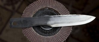
Drills, which are designed to produce centering holes, are made of high-speed steel. According to the requirements of the regulatory document, this material must provide the following hardness parameters for the working part of the tool with a diameter:
- less than 3.15 mm – 63–65 HRC;
- more than 3.15 mm – 63–66 HRC.
A separate category of centering drills, the manufacturing material of which contains cobalt (5%) and vanadium (3%), must have a hardness that is at least one unit higher than the above parameters.
The diameter of centering type drills may have deviations, the limit values of which are also specified in the regulatory document:
- for tools with a diameter over 5 mm – +0.15 mm;
- 2.5–5 mm – +0.12 mm;
- 0.8–2.5 mm – +0.1 mm;
- up to 0.8 mm – +0.05 mm.
Geometric dimensions of center drills
The regulatory document also lists the requirements for the condition of the surface of drills belonging to the centering type: there should be no cracks, nicks, tarnished colors or rough spots on it. It is accepted that tarnish colors may be present in the area of the grooves - where the grinding wheel exits.
The standard also specifies criteria for failure of the centering tool, which for drills with a diameter of up to 3.15 mm occurs in the event of their breakage, and for a tool with a diameter of over 4 mm - in the event of wear of its rear surface by the amount specified in the relevant tables.
The difference in the width of the feathers must be within the following limits for drills with a diameter of:
- up to 3.15 mm - no more than seven hundredths of a millimeter;
- more than 3.15 mm – no more than one tenth of a mm.
Damn.2. CENTER HOLES WITH 75° CONE ANGLE. Forms C, E
CENTER HOLES WITH 75° CONE ANGLE
| Form | Form |
Damn.2
_______________ * Dimensions for reference.
table 2
mm
| , no less | (premium shutdown according to H17) | (premium shutdown according to H17) | ||||
| 120 | 8 | 23,3 | 30,2 | 10 | 10 | 12,0 |
| 180 | 12 | 36,6 | 45,4 | 15 | 16 | 18,5 |
| 260 | 20 | 60,0 | 70,3 | 22 | 26 | 29,0 |
| 360 | 30 | 91,4 | 105,0 | 32 | 40 | 44,0 |
| 500 | 40 | 120,0 | 137,0 | 43 | 52 | 57,0 |
| 800 | 50 | 150,0 | 170,5 | 52 | 65 | 71,0 |
| 1200 | 63 | 186,0 | 213,7 | 65 | 80 | 88,0 |
Note. Recommended sizes.
An example of a symbol for the center hole of a mold with a diameter of = 8 mm:
Rep. prices
tr. S8 GOST 14034-74
Quality control
The drills used to make centering holes, as well as centering cutters, are professional tools, so they take a very responsible approach to monitoring their technical characteristics.
One of the most important stages of quality control of centering tools is their performance testing, which is performed on special samples made of steel 45, having a hardness of 187 to 207 units on the HB scale. During testing, the performance of the center drill being tested is compared with how another tool behaves under similar conditions, the rigidity and accuracy parameters of which are precisely determined.
Average operating time values for centering drills made of R6M5 steel
After checking it in metal processing, the centering drill should not have any chipping areas on its cutting part. Testers evaluate whether it can be used for further processing. The means used for such control are a magnifying glass and a measuring instrument, which is necessary in order to compare the geometric parameters of the drill being tested with their value indicated in the drawing. When checking the geometric parameters of the centering tool, the standard (GOST 8.051-81) allows for the following errors.
- A deviation of 25% from the tolerance specified in the drawing is allowed for the relative position of the tool surfaces and linear geometric parameters.
- A deviation of 35% from the specified tolerance is allowed for the angular parameters of drills.
The scheme for checking the geometric parameters of the tool is also presented in the aforementioned GOST. The rules for testing a centering drill for hardness, as well as recommendations for the use of measuring tools, are specified in GOST 9013-59.
The tool used to make centering holes is also checked for surface roughness, for which it is compared with another drill - a reference drill. The requirements for the roughness value of the tool surface are set out in the relevant standard (9378-75).
As during the machining process, when testing the centering tool, a cooling lubricant should be used, which is a 5% aqueous emulsol solution.
Scheduled tests performed on five or more instruments are carried out at the following frequency:
- check for trouble-free operation - twice a year;
- check for mean time to failure - once every three years.