Inverter welding machines are becoming increasingly popular among welders due to their compact size, low weight and reasonable prices. Like any other equipment, these devices can fail due to improper operation or due to design flaws. In some cases, you can repair inverter welding machines yourself by studying the design of the inverter, but there are breakdowns that can only be repaired in a service center.
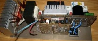
Welding inverter device
Depending on the model, welding inverters operate both from a household electrical network (220 V) and from three-phase (380 V). The only thing that needs to be taken into account when connecting the device to a household network is its power consumption. If it exceeds the capabilities of the electrical wiring, then the unit will not operate if the network is drained.
So, the inverter welding machine includes the following main modules.
- Primary rectifier unit. This block, consisting of a diode bridge, is located at the input of the entire electrical circuit of the device. It is this that is supplied with alternating voltage from the mains. To reduce the heating of the rectifier, a heat sink is attached to it. The latter is cooled by a fan (supply fan) installed inside the unit housing. The diode bridge also has overheating protection. It is implemented using a temperature sensor, which breaks the circuit when the diodes reach a temperature of 90°.
- Capacitor filter. It is connected in parallel to the diode bridge to smooth out alternating current ripples and contains 2 capacitors. Each electrolyte has a voltage reserve of at least 400 V, and a capacity of 470 μF for each capacitor.
- Filter for noise suppression. During current conversion processes, electromagnetic interference occurs in the inverter, which can disrupt the operation of other devices connected to this electrical network. To remove interference, a filter is installed in front of the rectifier.
- Inverter. Responsible for converting AC voltage to DC. Converters operating in inverters can be of two types: push-pull half-bridge and full bridge. Below is a diagram of a half-bridge converter with 2 transistor switches, based on devices of the MOSFET or IGBT series, which can most often be seen on inverter devices of the middle price category.
The circuit of a full bridge converter is more complex and already includes 4 transistors. These types of converters are installed on the most powerful welding machines and, accordingly, on the most expensive ones.Just like diodes, transistors are installed on radiators for better heat removal from them. To protect the transistor unit from voltage surges, an RC filter is installed in front of it.
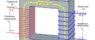
- High frequency transformer. It is installed after the inverter and reduces the high-frequency voltage to 60-70 V. Thanks to the inclusion of a ferrite magnetic core in the design of this module, it is possible to reduce the weight and dimensions of the transformer, as well as reduce power losses and increase the efficiency of the equipment as a whole. For example, the weight of a transformer that has an iron magnetic core and is capable of providing a current of 160 A will be about 18 kg. But a transformer with a ferrite magnetic core with the same current characteristics will have a mass of about 0.3 kg.
- Secondary output rectifier. It consists of a bridge that contains special diodes that respond to high-frequency current at high speed (opening, closing and recovery takes about 50 nanoseconds), which conventional diodes are not capable of. The bridge is equipped with radiators that prevent it from overheating. The rectifier also has protection against voltage surges, implemented in the form of an RC filter. At the output of the module there are two copper terminals, which ensure reliable connection of the power cable and ground cable to them.
- Control board. All operations of the inverter are controlled by a microprocessor, which receives information and controls the operation of the device using various sensors located in almost all components of the unit. Thanks to microprocessor control, ideal current parameters are selected for welding various types of metals. Electronic control also allows you to save energy by supplying precisely calculated and dosed loads.
- Soft start relay. To prevent the rectifier diodes from burning out from the high current of charged capacitors during startup of the inverter, a soft start relay is used.
General information about inverters
Transformer welding machines have a low cost compared to inverter welding devices and are simple in design, allowing for simple repair operations.
The main disadvantages include their dimensions, weight and sensitivity to the parameters of the power supply network.
At low voltage values (U), it is almost impossible to cook, since the power consumed by the device increases significantly, and electricity meters have a power limit of up to 6 kW.
As a result of this, the protection is triggered: the machine is triggered after a certain time due to heating or the fuses on the plugs burn out. If you install a circuit breaker with a higher value or use a “bug” (bypassing the fuse with a copper wire of a larger diameter), then the likelihood of a wiring fire increases.
In addition, when working with ordinary transformer welding, short-term changes in the U value occur, due to which other equipment and household appliances may fail. Transformer welding machines are relatively inexpensive and very easy to repair due to their simple design.
However, they have significant weight and are very sensitive to supply voltage (U). At low U, it is simply impossible to carry out welding work, since significant changes in U occur, as a result of which household appliances can fail. To avoid all these inconveniences during work, inverter devices are used.
Design and operating features
Inverter welding is used at home and in various enterprises. It ensures stable burning of the welding arc at high-frequency current. The device is designed as a powerful switching power supply (UPS), the operation of which is based on the principles of:
- Converting alternating supply (mains) U into constant.
- Conversion of direct to alternating high-frequency current.
- Current rectification while maintaining frequency.
If you follow these design principles, then there is a significant reduction in the welder by several hundred or thousand times. In addition, such a device allows you to equip the device with additional cooling.
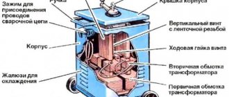
To carry out high-quality repairs of a welding inverter, you need to know the structure and principle of operation. Thanks to understanding the work, it is possible to correctly diagnose, find out the cause of the malfunction and eliminate it yourself. An inverter-type welding machine consists of main components (Figure 1):
- Rectifier.
- Inverter.
- Transformer.
- High frequency rectifier.
- Control circuit (electronic regulator).
Figure 1 - Block diagram of a welding inverter.
The rectifier consists of a semiconductor rectifier bridge and a filter made on a capacitor. The diode bridge rectifies the alternating current of the industrial supply network. When alternating current passes through a diode, current flows in one direction.
As a result, the current becomes constant, but it is dominated by significant ripples. Current with such parameters is not suitable for powering the inverter, since it only operates on direct current. To smooth out ripples, a large capacitance capacitor (2200.5000 µF) is used.
After conversion U, the inverter is powered. The inverter is a set of radio elements for generating the necessary variable U for a high-frequency pulse transformer.
The main elements are powerful key transistors and a microcircuit for receiving commands from the inverter control circuit, as well as for the correct operation of the latter. Transistors switch at a high frequency, which depends on the current model of the welder.
It can range from 35 to 95 kHz. The transistors are connected to a step-down pulse transformer.
The pulse transformer converts the incoming U received at the inverter output to low. A high-frequency rectifier is connected to the secondary winding of the transformer, which converts high-frequency alternating current into direct current. With this conversion, the frequency characteristics are preserved. Welding efficiency increases when using high frequency current.
The electronic regulator is used to monitor the operation of the device, diagnose and issue commands to the inverter. In addition, it allows you to change the welding current.
Thanks to this design, relatively mobile inverter welders have excellent characteristics:
- Primary power supply (mains U and current): 157.275 V and 20.30 A.
- Parameters U idle: 70.85 V.
- U when arcing: 22.35 V.
- Welding current setting range: 20.300 A.
- Load time at maximum I welding: 5.10 min.
- Electrode types: “1”, “2”, “3”, “4”, “5”, “6”.
- Average weight value: 5.7 kg.
Repair of inverter welding machines
To repair, it is necessary to study the circuit and malfunctions. Malfunctions can be divided into several groups: simple, medium and complex.
Simple breakdowns
Simple breakdowns usually occur when any instrument or device is operated incorrectly. This type of fault does not require special qualifications and consists mainly of primitive breakdowns that can be fixed very easily and quickly.
You should be very careful when solving the problem of repairing inverter welding with your own hands, since a simple breakdown due to rash actions can lead to more serious consequences. Simple malfunctions include the following types:
- Lack of mains power to the inverter (the inverter “refuses” to turn on).
- Housing humidity.
- Dust inside the inverter apparatus.
- Unstable arc.
- Lack of full power of the device.
- Electrode sticking.
- Loosening of fastenings.
- Spattering of metal.
The lack of mains power is possible for several reasons: lack of U, defective inverter power cable, blown fuse. In addition, there is a possibility of failure of the device’s electronics, but this malfunction is not a simple one, as it requires certain skills. The solutions are very simple.
For example, if there is no power supply U, you need to measure it with a voltmeter in the outlet. If the network cable breaks, you need to ring it, find the problem area and replace it. If a fuse burns out, it should be replaced with a serviceable one (you cannot install a “bug”, as this can lead to permanent failure).
When working in a damp room, you need to dry the contents of the welder. You cannot start it, as it will constantly knock out the machines and burn out the fuse thread. It should be remembered that moisture is the worst enemy of any equipment.
Dust is an excellent conductor of electricity. The welding machine must be cleaned periodically. Dust can lead to more serious consequences.
If the arc is unstable and metal is spattering, the welding current should be checked. Basically, the elementary solution to the problem is to increase it. There is a certain dependence of the current on the thickness of the electrode: the diameter of the electrode must be multiplied by 20-40 A. When calculating, the required current strength is obtained.
For example, during operation, electrode “4” and current for comfortable operation (at normal input voltage) are used: I = 4 * 40 = 160 A. The choice of values from the range from 20 to 40 depends on the thickness of the metal: for every 1 mm there is a coefficient multiple of 5. For example, you need to calculate the welding current for 2 mm metal and electrode “3”.
The calculation algorithm is as follows:
- Maximum welding current: Iw = 3 * 40 = 120 A.
- Current for 2 mm of metal: I = Ist - 2 * 5 = 120 - 10 = 110 A.
This algorithm is used with normal network U (210.225 V). At 110 A, welding work will be performed carefully and the likelihood of burning through the metal is minimal.
When the electrode sticks, the culprit is a reduced U of the supply network, and to eliminate this problem it is necessary to increase the welding current. In addition, you need to clean the sockets and contacts, and also check the carrying wire, since its cross-section must be more than 3 square meters. mm.
Periodic shutdown of the device occurs as a result of overheating. In this case, you need to let it cool for 25-40 minutes.
How does an inverter work?
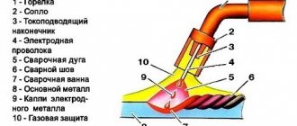
Below is a diagram that clearly shows the principle of operation of a welding inverter.
So, the operating principle of this welding machine module is as follows. The primary rectifier of the inverter receives voltage from the household electrical network or from generators, gasoline or diesel. The incoming current is alternating, but when passing through the diode block it becomes constant. The rectified current is supplied to the inverter, where it is converted back into alternating current, but with changed frequency characteristics, that is, it becomes high-frequency. Next, the high-frequency voltage is lowered by a transformer to 60-70 V with a simultaneous increase in current. At the next stage, the current again enters the rectifier, where it is converted into direct current, after which it is supplied to the output terminals of the unit. All current conversions are controlled by a microprocessor control unit.
How to measure inverter current
How to measure inverter current in a simple and accessible way
Novice welders very often wonder how to measure the inverter current. It would seem, why measure the current at the output of the welding machine?
In fact, most problems when welding with an electrode are due to the fact that the inverter produces incorrect current values. In this case, everything seems to be set correctly, the voltage in the network is normal, but the inverter does not want to cook.
Let's figure it out, so what is the easiest way to measure the current of the inverter in order to find out how many amperes it produces at the output.
Causes of inverter failures
Modern inverters, especially those made on the basis of an IGBT module, are quite demanding in terms of operating rules. This is explained by the fact that when the unit operates, its internal modules generate a lot of heat. Although radiators and a fan are used to remove heat from power components and electronic boards, these measures are sometimes not enough, especially in inexpensive units. Therefore, you need to strictly follow the rules that are indicated in the instructions for the device, which imply periodically turning off the unit to cool down.
This rule is usually called “On Duration” (DS), which is measured as a percentage. Without observing the PV, the main components of the device overheat and fail. If this happens to a new unit, then this breakdown is not subject to warranty repair.
Also, if an inverter welding machine operates in dusty rooms, dust settles on its radiators and interferes with normal heat transfer, which inevitably leads to overheating and breakdown of electrical components. If the presence of dust in the air cannot be eliminated, it is necessary to open the inverter housing more often and clean all components of the device from accumulated contaminants.
But most often inverters fail when they operate at low temperatures. Breakdowns occur due to the appearance of condensation on the heated control board, resulting in a short circuit between the parts of this electronic module.
How to measure inverter current
It's no secret that cheap inverters very often make mistakes in adjusting the welding current. Often, a beautiful and neat regulator handle serves only for beauty, but not for adjusting the welding current.
For example, a very common problem with many welding machines is the error in delivering the desired amperes. That is, a 250 Ampere welding machine does not produce the same amount. In this case, various kinds of problems arise when welding metals.
The easiest way to measure the current of a welding machine is to use special measuring clamps. The operating principle of these clamps is based on the action of inductance coils. However, this method of measuring the amperage of a welding machine is only suitable if it produces a “change”.
To measure the welding current in inverters, you must use an ammeter, which is connected through a shunt. In this case, it is very important not to connect the ammeter directly to the inverter, but this must be done through a shunt. Thus, you will be able to find out the whole truth, and how much maximum amperes of welding current you can squeeze out of the inverter.
To measure the current of a 250 Ampere inverter, a 250 Ampere shunt is sufficient. The shunt is necessary to relieve the voltage, otherwise the ammeter may burn out. The shunt is connected in parallel with the ammeter into the gap of the welding cables.
It should be noted that this amperage test circuit is only suitable for welding inverters. That is, welding machines that issue a “permanent”.
Repair features
A distinctive feature of inverters is the presence of an electronic control board, so only a qualified specialist can diagnose and repair faults in this unit . In addition, diode bridges, transistor units, transformers and other parts of the electrical circuit of the device may fail. To carry out diagnostics yourself, you need to have certain knowledge and skills in working with measuring instruments such as an oscilloscope and a multimeter.
From the above, it becomes clear that, without the necessary skills and knowledge, it is not recommended to start repairing the device, especially electronics. Otherwise, it can be completely damaged, and repairing the welding inverter will cost half the cost of a new unit.
Do-it-yourself welding inverter repair: diagrams and diagnostics, how to repair
In a short time, inverter welding machines have gained unprecedented popularity among specialists. Despite the reliability of the power supply, repair of a welding inverter may sometimes still be necessary.
Diagnosis of a malfunction and replacement of a failed part, if you have some skill, can be done at home. To carry out repairs, you must first familiarize yourself with the design of the device and only then proceed with the repairs.
Common causes of breakdowns
Do-it-yourself repair of welding inverters is possible for the following faults:
- Unstable welding arc. In most cases, such a malfunction is associated with an incorrect choice of the inverter operating mode. To select the optimal current strength, you can follow the rule: 20 to 40 amperes of current should be supplied per 1 millimeter of electrode diameter.
- The appearance of forces when separating the electrode from the metal. A typical malfunction that occurs due to low voltage coming to the electrodes. The simplest way to solve this problem is to clean the contacts of the power supply from oxides and carbon deposits.
- No welding jet. If there is no power when you turn the toggle switch to turn on the device, you should check the voltage in the electrical network.
- Inverter shutdown during prolonged operation. As a rule, such behavior of the inverter can be associated with overheating. The way out is simple: let the device cool down and start working again after 30 minutes.
When diagnosing a welding machine, the following faults may be detected:
- arising as a result of incorrect choice of welding mode;
- arising as a result of failure of electronic components of equipment.
In any of the above cases, you can repair the welding inverter yourself.
Most malfunctions of this welding machine unit are associated with the failure of electronic components.
The main types of electronic circuit faults are presented:
- Moisture entering the inverter housing. Oxidation of conductive paths due to moisture ingress can cause a breakdown in contact between the main components of the device.
- Formation of a large amount of dust on the main working elements. Excessive dust contamination of inverter elements can disrupt the natural circulation of air in the housing and lead to overheating of electronic components.
- Selecting the wrong operating mode for the inverter, resulting in overheating of electronic components. Inverter failure due to overheating of electronic components is one of the most common failures.
Most inverters use:
- input rectifier;
- output rectifier;
- key control unit;
- cooling system.
General procedure for diagnosing welding inverters
Before repairing the device, you should check the functionality of the cooling system. Cooling radiators clogged with dust remove heat from the power elements much worse, which means the fins should be completely cleaned of dust and other debris.
Repair of inverter welding machines should begin with diagnosing the input rectifier.
To fully check this node you should:
- disassemble the module;
- remove the radiator;
- remove the diode bridge;
- ring the contacts of the diode bridge.
If no problems with the diode bridge are identified, you should move on to the next module - the output rectifier.
Typical inverter faults.
The functionality of the output rectifier is checked using the following algorithm:
- disassemble the module;
- unsolder the diode assemblies;
- ring the diodes.
In addition to diodes, the output rectifier circuit contains radiators that should be installed back after repairing the module.
After examining the output rectifier, you should proceed to diagnosing the key module.
This inverter module consists of:
- four groups of transistors;
- key control boards;
- smoothing rectifiers.
The procedure for examining the key module is as follows:
- Checking transistors. As a rule, a faulty element is clearly visible to the naked eye. If this is not the case, then you should check the sequence of all available transistors with a tester.
- If measurements with a tester do not produce results, you need to diagnose the transistor assemblies using an avometer, measuring the resistance.
- If all components appear to be in good working order, all transistors should be unsoldered one by one. This diagnostic method is suitable if there is a short circuit on the board.
Most inverter problems can be diagnosed by carefully inspecting the electronic components. If defective parts are identified, you should immediately remove them and replace them with similar characteristics.
Repair of inverter power unit
Electrical circuit of a welding inverter. To repair the inverter power unit, the following tools may be required:
- pliers;
- two soldering irons with a power of 40 and 100 watts;
- screwdrivers of various types;
- wrenches and socket wrenches;
- knife;
- wire cutters;
- tester for electrical network;
- oscilloscope;
- calipers;
- micrometer.
The most typical breakdown of the power unit of a welding inverter is the failure of a powerful transistor. In most cases, a damaged transistor can be identified visually: it has defects, burnouts or deformation. Repairing an inverter if a defective transistor is detected is reduced to replacing it.
There are many cases when a transistor breakdown is only a consequence and not a cause. With this development of events, replacing the transistor assembly may not give a visible effect.
Before repairing the diode bridge, you should check the functionality of all elements. This can be done by alternately measuring the resistance on the legs of the elements. If the resistance between the multimeter probes located on the diode legs is zero or infinity, then this element should be replaced.
New transistors or diodes should be selected from analogs with similar characteristics. As a rule, analogues of the vast majority of models of electronic components are available for sale.
Components of a welding inverter.
When repairing the inverter power unit, you should adhere to the following rules:
- Do not use an electrical appliance with an open insulating casing.
- Diagnostics and replacement of all electronic components must be carried out on a de-energized welding machine.
- It is best to remove accumulated dust and debris from the device using a compressor or a can of compressed air.
- Cleaning the board from sticky traces and used flux should be done using plastic-neutral solvents. It is recommended to use a special brush for cleaning electronic components.
- A working device should be stored in a disconnected state and with the casing completely closed.
Conclusion
Repairing welding inverters with your own hands is a fairly trivial task that requires little knowledge and skills in the field of electrical engineering. Most malfunctions of inverter power supplies can be repaired after a simple diagnosis of key power units.
When restoring the functionality of the inverter yourself, it is important to acquire a soldering iron, flux, multimeter and oscilloscope. When inspecting and repairing, it is important to completely de-energize the electronic device so as not to expose yourself to the risk of electric shock.
Source: https://tutsvarka.ru/oborudovanie/remont-svarochnogo-invertora
Main malfunctions of the unit and their diagnostics
As already mentioned, inverters fail due to the impact of external factors on the “vital” units of the device. Also, malfunctions of the welding inverter can occur due to improper operation of the equipment or errors in its settings. The most common malfunctions or interruptions in the operation of inverters are:
The device does not turn on
Very often this breakdown is caused by a faulty network cable of the device. Therefore, you first need to remove the casing from the unit and ring each cable wire with a tester. But if everything is in order with the cable, then more serious diagnostics of the inverter will be required. Perhaps the problem lies in the standby power supply of the device. The method of repairing the “duty room” using the example of a Resanta brand inverter is shown in this video.
Welding arc instability or metal spattering
This malfunction may be caused by incorrect current setting for a certain electrode diameter.
Advice! If there are no recommended current values on the packaging for the electrodes, then it can be calculated using the following formula: for each millimeter of equipment there should be a welding current in the range of 20-40 A.
Welding speed should also be taken into account. The smaller it is, the lower the current value must be set on the control panel of the unit. In addition, to ensure that the current strength corresponds to the diameter of the additive, you can use the table below.
Welding current is not adjustable
If the welding current is not regulated, the cause may be a breakdown of the regulator or a violation of the contacts of the wires connected to it. It is necessary to remove the unit casing and check the reliability of the conductor connections, and, if necessary, test the regulator with a multimeter. If everything is in order with it, then this breakdown can be caused by a short circuit in the inductor or a malfunction of the secondary transformer, which will need to be checked with a multimeter. If a malfunction is detected in these modules, they must be replaced or rewound by a specialist.
High power consumption
Excessive power consumption, even if the device is without load, most often causes an interturn short circuit in one of the transformers. In this case, you will not be able to repair them yourself. You need to take the transformer to a mechanic to rewind it.
The electrode sticks to the metal
This happens if the network voltage drops. To get rid of the electrode sticking to the parts being welded, you will need to correctly select and configure the welding mode (according to the instructions for the device). Also, the voltage in the network may sags if the device is connected to an extension cord with a small wire cross-section (less than 2.5 mm2).
Often, a drop in voltage causing electrode sticking occurs when using a power extension cord that is too long. In this case, the problem is solved by connecting the inverter to the generator.
Overheat light on
If the indicator is on, this indicates overheating of the main modules of the unit. The device may also turn off spontaneously, which indicates that the thermal protection has tripped. To prevent these interruptions in the operation of the unit from occurring in the future, it is again necessary to adhere to the correct duty cycle (ST). For example, if duty cycle = 70%, then the device should operate in the following mode: after 7 minutes of operation, the unit will be given 3 minutes to cool down.
In fact, there can be quite a lot of different breakdowns and the reasons that cause them, and it’s difficult to list them all. Therefore, it is better to immediately understand what algorithm is used to diagnose a welding inverter in search of faults. You can learn how to diagnose the device by watching the following training video.
Procedure for repairing devices
Failure and failure of the welding inverter can occur either due to a serious breakdown or due to a minor malfunction. Before contacting a service center or a familiar technician, it makes sense to consider the option of doing the repair yourself, especially if the owner has specialized education or amateur radio skills. The inverter should be disassembled, cleaned and carefully inspected from the inside, as the problem may be excess dust or some loose wiring, and no major repairs are really needed.
If you decide to carry out repairs yourself, then the following minimum set of tools is required:
- Digital multimeter. The most common one, the “diode test” function is optional, since all semiconductors can be checked in resistance measurement mode.
- Soldering iron with accessories. A soldering station is better, but you can get by with a soldering iron with a thin tip of 40–60 W.
- Screwdrivers, pliers, wire cutters, tweezers.
It is often written that to check the condition of an inverter device you definitely need an oscilloscope. But this is a different level of knowledge and skills with different recommendations for troubleshooting. Our actions for diagnosing and repairing the inverter will be limited to a visual inspection, continuity testing, basic measurements of the condition of the main elements of the inverter’s electronic circuit and their replacement in the event of a malfunction. If all this does not bring results, then you need to contact specialized specialists.
The procedure for the first stage is as follows:
- Remove the housing and clean the inverter from dust with compressed air. Select the pressure so as not to damage printed circuit boards and electronic components.
- Check the condition of the fan blades and the ease of their rotation. If problems are found, replace them with new ones. Check that all wires and connectors are securely connected.
- Check the connection and condition of the welding current adjustment potentiometer. In case of malfunction, repair or replacement.
- Inspect the windings of transformers and chokes for burning. If there are defects, dismantle and send for inspection or immediately rewind.
- Check the elements of the power circuit (capacitors, charging resistor, diodes, transistors) for damage to the external housing. If defects are found, replace with the same or analogues.
- Carry out an external inspection of the control system printed circuit board. If there are damaged elements, then carefully remove them and replace them with new ones (if you have never soldered printed circuit boards, then it is better not to do this, but immediately contact a specialist).
If, after an external inspection and elimination of detected problems, the inverter does not turn on or operates incorrectly, it is necessary to diagnose individual circuits and power elements (see below).
Inverter diagnostics
Testing of semiconductor electronic components is carried out by measuring the resistance at their terminals by changing the polarity of the multimeter. In one case it should be close to zero, in the other - infinitely large.
Before you begin diagnosing the inverter, you must connect a 100÷150 W incandescent light bulb in series with it, which will stabilize the current and serve as protection against short circuits. In addition, by the glow of the light bulb one can judge the working condition of capacitors and power transistors.
We diagnose the inverter in the following sequence:
- Checking the power diodes of the output rectifier. We measure the resistance at the output terminals of the inverter with a multimeter. One way should be zero, the other should be infinity. If this is not the case, then we proceed to repair: we identify the faulty diode and replace it.
- Checking the power transistors of the RF converter. First you need to determine the type of arrangement of the transistor pins. We measure for “breakdown” by changing the polarity between the gate and the other two terminals. If it is zero in both directions, then the transistor is faulty and must be replaced.
- Checking the diodes of the LF rectifier. Here the diodes are connected in a bridge circuit, so first you need to determine the four contact points. At zero in both directions the diode must be replaced.
- If all power semiconductors of the devices are in good condition, you can connect the inverter to the network. In this case, the light bulb connected in series with it will first flash for a few seconds, and then, as the LF rectifier capacitors charge, it will begin to dim noticeably. If at least one of the transistors of the RF converter is broken, the light bulb will burn at full intensity.
- The inverter can then be turned on and off several times using the key on the front panel. After this, it is necessary to measure the open circuit voltage in several positions of the current regulator (it will be slightly less than the nominal one).
Before repairing the welding inverter, it must be disconnected from the power supply. The light bulb circuit can only be used at idle. It is best to check the device under load with a ballast rheostat.
Replacing transistors
When repairing a welding inverter, you may have to replace transistors, zener diodes, resistors and other electronic parts. To do this, you need to have some skills in soldering such products. When replacing transistors (IGBT and MOSFET), you must remember that they can fail under the influence of static electricity. It is recommended to work with them on antistatic surfaces and wearing wristbands to protect against static. In fact, few people fully follow these instructions, but it is still necessary to know about them.
In order to replace the power transistor, you need to unscrew the screw that holds it to the radiator, separate its body from the surface, and then carefully unsolder it. Installation of the new transistor is carried out in the reverse order; before pressing it with a screw to the radiator, you need to apply a thin layer of heat-dissipating paste to the contact point.
Rectifier repair
The inverter contains three rectifiers: a half-wave output and two bridge rectifiers: an input and an internal power supply (“standby”). The first one contains two diodes and is checked with a multimeter through the input terminals of the inverter, and bridge diodes - at four points (on the connectors or on the board). When repairing rectifiers, diodes, capacitors and ballast resistors are most often replaced. There are no special precautions when soldering these elements, although when replacing parts of the internal power supply you need to be extremely careful: they are installed on the printed circuit board. The diodes of the input and output rectifiers are mounted on radiators. When installing a new element, be sure to use heat-dissipating paste before fixing it with a clamping screw.
Capacitor diagnostics
The main reasons for the failure of electrolytic capacitors are mechanical damage, significant excesses of the rated voltage, failure of internal contacts and aging. In the first two cases, malfunctions can be detected visually, while the ends of most models of electrolytic capacitors have special notches that rise or open when the electrolyte “explodes” (see photo below).
Figure 7 — Capacitor diagnostics
Hidden faults are quite easily detected by a device with a capacitance measurement function or a conventional multimeter. In the latter case, the pre-discharged capacitor initially shows a small resistance, which increases to infinity as it is charged from the multimeter source. When measuring at the contacts of a faulty capacitor, the device shows either an open circuit or some kind of constant resistance.
Control board repair
If simple diagnostics with a multimeter and subsequent repairs do not give the desired result, then the source of the problem is most likely the control board. Without an oscilloscope, here you can only check the voltage values at the contact points of the board indicated on the diagram, as well as measure the supply voltages and ring the semiconductor devices (which, most likely, will have to be soldered). In addition, to repair the control board, you need good knowledge of radio electronics and the ability to understand the circuits of electronic devices. For those who do not have such qualifications, there is only one option left - to a service center or to a specialist with a good reputation.
We think this article lists all the possible steps to diagnose inverter faults using a multimeter. If we missed any important points, write about it in the comments and tell us about your experience in repairing an inverter device.
PS. Experienced and serial production of printed circuit boards with a guarantee can be viewed at this link.
Real current strength in inverter-type welding machines
When choosing a welding inverter before purchasing, one of the first parameters that buyers pay attention to is the current strength of the device. It just so happens that the Ukrainian consumer gives preference to more powerful tools. And today most manufacturers actively use this.
In this article we want to understand the indicated and real current strength of welding inverters, tell what marketing moves manufacturers use so that you would give preference to their product, and we will also try to tell you what real current strength in a welding inverter will be required, depending on the assigned tasks and operating conditions of the welding machine.
How to measure the open circuit voltage of a welding inverter?
Good afternoon. Tell me how to measure the open circuit voltage of a welding inverter? I have a GYSmi 161, according to the passport 75 volts... but I have vague doubts. Thank you in advance.
An oscilloscope. Or devices that measure using the True RMS method.
What is it? Where should I put the oscilloscope?
What kind of TruERMeEs and oscilloscopes are there? Poke a regular Chinese tester and measure the constant. Delov then. This is not a microwave generator, but just a DC current source. And the surges and unevenness of the output voltage present at its output are a consequence of insufficiently complete smoothing (filtering). True, some inverters can reduce the voltage at idle for safety reasons. But this is clearly not your case.
moskow wrote: Where should I put an oscilloscope?
moskow wrote: how to measure the open circuit voltage of a welding inverter?
One probe of the device is to the output terminal “+”, the second, respectively, to the “-“.
Konstantin M wrote: Poke a regular Chinese tester and measure the constant.
Or better yet, several “ordinary” (i.e. cheap) Chinese testers - they will all show different voltages.
Thank you all very much!
Konstantin M wrote: Poke a regular Chinese tester and try it on
Just don't be surprised by anything!
avaks wrote: Just don't be surprised at anything!
I was really surprised, I measured it with a Chinese tester and it shows from 75 to 90, these are the indicators for PICO 162, so it is an order of magnitude higher.
Well, Moskow, you have found out the no-load voltage of your inverter. Did you think - there is a strict straight line? And if you used an oscilloscope, you would be even more surprised. Well, you saw some kind of crookedness there, and what next? How to interpret? And, most importantly, WHY?
Then, to find out that in inverter welding technology, voltage xx is not such an important parameter as with a transformer. There may even be almost no voltage, let’s say some 10V standby voltage. and the dynamic properties, well-thought-out control laws, allow you to freely burn the UON, and a welder with 80V doesn’t burn this UON at all.
Konstantin M XX in inverters the main indicator is the ability to use different electrodes in operation. If XX is low, you will be exhausted working with the SSSI. I looked at it with an oscilloscope on my SAI. The purest constant.
I bought an ARC 209B and looked at the output switches with an oscilloscope, and there the meander does not change when adjusting the current, but at idle, is that how it should be? Is there a blockage to the load flow? I can’t cook yet because I’m in a mountain apartment,
a know-it-all wrote: I bought an ARC 209B and looked at the output switches with an oscilloscope, and there the meander does not change when adjusting the current, but at idle, is that how it should be? Is there a blockage to the load flow? I can’t cook yet because I’m in a mountain apartment,
know-it-all, This is probably Svarog with bsn? Here the oscilloscope shows bsn. I measured it with a household multimeter, and made the load from a solution of a teaspoon of salt in a half-liter jar and two metal plates.
Vitaly S 31 wrote: I made the filling from a solution of a teaspoon of salt
Chlorine is a poisonous gas, causes suffocation, better than soda
Why is it so important to know how many amps the inverter produces?
In fact, this is very important, because if the inverter does not produce the desired amperes, then it will not be possible to use electrodes of a certain diameter. Various types of problems may also arise during welding when the electrode begins to stick to the metal.
And here you can blame as much as you like on low-quality electricity or on the fact that the electrodes are bad. Knowing how many amperes a welding inverter actually produces is very important in order to cook normally and efficiently.
So you know how to measure the inverter current. Subscribe to the MMA Welding in Zen channel and receive a new portion of useful information. Good luck to all.
Source