Electrical diagram
The main purpose of using machine electrical equipment is to connect devices that provide signals and lighting.
The same applies to all power plants. The basis is a standard three-phase electrical network. The technical data sheet of the device requires that the network itself be equipped with a solidly grounded wire. Otherwise, using the machine becomes impossible. Relay-contact and electrical type equipment will only work properly if maintenance is carried out promptly and correctly. The simplicity of the design also ensures trouble-free operation.
Domestic experts have always considered the machines of the 1V62G series as one of the most reliable. The reason is the stability of electrical equipment under any conditions. Operators with an average level of qualifications can be allowed to operate. Any ordinary person will be able to use the unit without any problems if they study the device passport in advance and follow all the instructions from the manufacturer.
Download the diagram in full size
Features of the system
There are several features that it is recommended that you familiarize yourself with before starting work.
- The power of the main drive motor is 7.5 kilowatts.
- This part is launched by a push-button station using a special key. The input switch must remain in the on state, otherwise work operations are unacceptable.
- Another key is provided to stop the device.
- The drive for fast movements operates at a power of 0.75 kilowatts. The jog button is applied during power-on. When it is clamped, contact occurs with the limit switch. Hides in the handle of the apron.
- 0.12 kilowatts is the power of another small motor that powers the devices. This part is switched on using a special cabinet. The electrical cabinet is located at the rear of the tailstock.
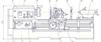
Kinematic diagram of a screw-cutting lathe 1A62G
Kinematic diagram of lathe 1a62g
Main movement chain
The rotation of the product, fixed in the headstock chuck or in the centers, is carried out by an individual electric motor (Fig. 2).
The movement from the electric motor is transmitted through a V-belt drive to the drive pulley and then through the gears of the gearbox mechanism to the spindle.
The spindle speed is changed by moving gear blocks 6-7, 11-13, 17-18, 19-20 along the spline rollers using handles A and B (Fig. 2 and 3) and switching gears 24 or 26 using clutch 25 and handles B.
21 different speeds and 3 overlapping speeds from 11.5 to 1200 rpm with forward spindle motion are carried out according to the following kinematic chains: from shaft 1, which has 730 rpm, rotation is transmitted to shaft 11 by gears 1-6 or 2-7 . Next, rotation is transmitted to shaft III by a switching gear block 11-13, which respectively meshes with gears 8, 9 and 10. When gear 26 is engaged, rotation is transmitted from shaft III by gears 14 and 26 to Spindle 17. When gear 24 is engaged, gears 15-17 or 16-18 the movement is transmitted to shaft IV, gear wheels 19-22 or 20-21 - to shaft V and permanently coupled gear wheels 23-24 - to spindle VI.
Feed chain
The longitudinal and transverse movement of the caliper is carried out either using the drive shaft XVIII through the feed box and apron mechanisms, or using the lead screw 76 and the nut 77 through the feed box mechanism, or manually through the gears of the apron mechanism 78, 73, 74 and rack 75 with a handwheel 89.
To cut precise threads, the lead screw 76 can be connected directly to the shaft of the replacement gears XII by couplings 90, 91 and 92.
The feed box receives movement through gears 25 and 27 (gearbox mechanism) and 28-36 (reverse and replacement gears of the guitar).
Without using a link to increase the pitch through the feed box mechanism through a lead screw 76 with a pitch of 12 mm, the following threads are obtained:
- inch from 2 to 24 threads per 1″;
- metric in increments from 1 to 12 mm;
- modular with modules from 0.5 to 3;
- pitch with diametric pitch from 96 to 7.
Using the pitch increasing mechanism, it is possible to obtain threads with an increased pitch, 16 times larger than normal.
Through the running shaft, the caliper receives longitudinal feeds from 0.082 to 1.59 mm (when gears 70 and 71 of the apron mechanism engage) and transverse feeds from 0.027 to 0.52 mm (when gears 70 and 81 engage).
The direction of movement of the caliper when cutting left-hand threads is changed by rearranging the gear 31.
The transverse movement of the caliper is carried out manually through the screw 83 and the nut 84 with the handle 93. The upper slide 94 is moved only manually with the handle 95 using the screw 85 and the nut 86.
The tailstock quill is also moved manually by handwheel 96 using screw 87 and nut 88.
Tables of screw-cutting lathe 1V62G
Main nodes
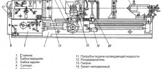
Main components of the 1V62G machine
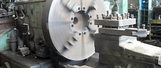
- The machine has a cast iron frame (6) with two pedestals. The frame guide profiles are T-shaped on one side and dovetailed on the other, and have wedges for adjustment. Taken together, this allows the support to be held rigidly, thereby increasing the accuracy class in comparison with other machines that have simple prismatic profiles.
- On the left side of the frame there is a headstock (4), which houses the gearbox. It contains handles for changing speeds and feeds. The headstock can be rotated in the grooves, which allows for an offset of the center and turning of flat cones.
- On the right side of the frame there is a movable tailstock (10). By means of a rotating center in the quill, the headstocks are pressed and long workpieces are processed. The headstock is provided with a mechanical clamp and smooth movement due to the air cushion. Thanks to the conical hole in the tailstock quill, drills, countersinks, taps, reamers and centers, rotating and stationary, can be inserted into it. This allows for drilling, countersinking and pressing of the part.
Tailstock of machine 1V62G
- An apron (8) is mounted at the bottom in the middle. It transmits the movement of the caliper, and also, with the help of a screw, allows you to cut threads in parts
- Above the apron there is a carriage and a support (7), on which there is a tool holder with a rotating head
- The chuck and support guard (5 and 9) serve to protect the turner from chips and coolant
- The electrical cabinet (2) is located behind the machine. It contains all electrical controls
Designation of product parts for modifications
High-quality materials from steel and cast iron are used to assemble the unit’s key parts; the frame has polished surfaces, which increases the service life and allows repairs to be carried out according to the plan provided by the manufacturer.
The gearbox, apron and feed box are equipped with forced lubrication, which increases the service life of rubbing parts.
Table for cutting threads on a lathe 1V62G
On a threading lathe, you need to adjust the feed box gears and the feed guitar gears so that they engage. This timing is adjusted so that the movement of the cutter on the slide produces a tooth profile in one spindle revolution. For this purpose, there are thread cutting tables, according to which, using handles and levers, various combinations of gear meshing are adjusted.
Threading machine setting table
Good to know. Inch threads with threads 11 and 19 can be cut without rebuilding the gears in the block of replacement gears. This is a feature of this model.
The machine has 3 three-phase motors:
- for the main drive 7.5 kW;
- for caliper movement
- for coolant.
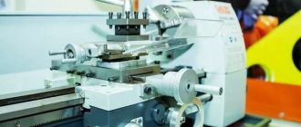
1E61MT high precision screw-cutting lathe. Purpose and scope
Lathes of the 1E61MT models are created on the basis of the 1E61M machine and belong to the class of light lathes.
The screw-cutting lathe model 1E61MT is universal and is designed to perform finishing operations when turning high-precision parts and cutting various threads. Machine accuracy class – B.
Description of the design of a screw-cutting lathe
The 1E61MT machine is driven by an individual electric motor with a power of 4.5 kW and a rpm of 1335.
The movement is transmitted to the receiving pulley of the gearbox by a V-belt drive. From the gearbox, six V-belts transmit the movement further to the headstock pulley, and then, using a toothed coupling, to the spindle.
High precision threading is achieved by connecting the lead screw directly to the corresponding set of replacement gears on the guitar, bypassing the entire feed chain.
The machine also allows you to cut threads of normal accuracy using a feed box.
The feed chain of the machine has a pitch increasing link, through which an eightfold increase in the table value of feeds and thread pitches is achieved.
By turning on the step increasing link, you can cut steep threads, cut all kinds of steep spirals, cut multi-start worms and perform a number of special jobs.
The machine apron has a “falling” worm mechanism that automatically turns off longitudinal and transverse feeds when working with fixed stops. At the same time, this mechanism protects the machine from damage due to overload. But when working with a lead screw, it is unacceptable to use a longitudinal stop.
In the middle part of the spindle head there is a wedge drive pulley mounted on two ball bearings. Thus, the spindle is relieved from the tension of the V-belts.
The headstock is automatically lubricated by a separate oil pump. The switching on of the main electric motor and the switching on of the oil pump are interlocked, which eliminates the possibility of the spindle head operating without lubrication.
The supply of cutting fluid to the cutting zone is carried out by an electric pump, which is turned on as needed from a separate switch.
Reversing the main movement of the machine is electrical. The spindle rotation is braked by countercurrent in the electric motor.
The high-slip electric motor used on the machine ensures an increase in the reversing frequency when cutting threads.
The production capabilities of the machine are significantly expanded with the help of a number of additional accessories included with the machine upon special order at an additional cost.
The machine provides high accuracy subject to the following points:
- Do not install the machine near impact machines or machines that cause external vibrations.
- The machine should be installed in a clean, bright room, but at the same time it should be protected from direct sunlight.
- Do not install the machine near heating appliances.
- The room temperature should be maintained within 18-20° C.
TV-01 – 1949, the first model of a series of screw-cutting lathes, Ø 340 x 1000 mm
TV-01M – screw-cutting lathe
– 1955, high-precision screw-cutting lathe, Ø 320 x 750 mm
– 1965, high-precision screw-cutting lathe, Ø 320 x 710
– high-precision screw-cutting lathe, Ø 320 x 710
1E61MTS – specialized high-precision screw-cutting lathe
– 1975, high-precision screw-cutting lathe, Ø 320 x 710
1E61PMa – high-precision screw-cutting lathe, B/s main drive, Ø 320 x 710
1E61PMF3 – high precision CNC lathe “FS-2K”, Ø 250 x 630
– specialized high-precision screw-cutting lathe, Ø 320 x 710
UT16P, UT16V – 1982, high-precision screw-cutting lathe, Ø 320 x 710 mm
– 1987, high-precision screw-cutting lathe, Ø 320 x 750 mm
– 1987, high-precision screw-cutting lathe, used main drive
UT16F3 – 1983, CNC screw-cutting lathe “Luch-2T”, Ø 200 x 630 mm
UT16D – high-precision screw-cutting lathe
Main technical characteristics of the 1V62G screw-cutting lathe:
In addition to the basic parameter 1V62G, the plant produced machines of other modifications: 16V20; 1V625M.
- Accuracy class-8. On such machines it is possible to process parts with high precision, down to several microns, which makes it possible to do without grinding specified surfaces (for example, a journal for a bearing seat)
- Defining dimensions: Maximum dimensions of workpieces in mm:
- above the surface of the bed 445;
- above the caliper 220 to 290;
- taking into account the depression in the frame 620;
- parts can be sharpened with a length of no more than 1500 mm
Controls
The front panel of the device contains the following unit controls:
- A handle that sets the required spindle rotation speed.
- The handle increases the thread of the workpiece.
- A handle that sets the left or right direction for threading.
- A handle that regulates the feed and thread pitch.
- A handle that operates a lead screw or a lead roller, which is used only for quiet running.
- A handle that regulates the forward or reverse rotation shaft of the motor on the main drive.
- A handle that changes the direction of the support when turning a part, switching between the longitudinal and transverse direction of feed.
- The organ that controls the apron.
- A handle that turns the mechanical feed mode on and off for using the flywheel, engaging the lead screw and moving the longitudinal slide.
- The handle, which controls the manual feed on the caliper, fixes the cutting heads, and moves part of the spindle.
- A handle that secures the tailstock, together with a flywheel that ensures its smooth movement.
Important! Also, the presence of electrical switches to illuminate the workplace. Switch for the pump that cools the machine
And a button responsible for starting the engine.
Gearbox
There were 30 possible speeds for the gearbox, but due to a coincidence with the number of revolutions in the spindle assembly, their number was reduced to 21 different types.
The handle on the gearbox contains information about the number of revolutions of the spindle assembly and turns in different directions depending on the type of work until the pointer shows the required number of revolutions.
Reverse
Used for fixing parts.
Options:
- Comes with a diameter and size having a through shape - 3.6 cm.
- With an acceptable rod size of no more than 3.8 cm.
- With several stages of rotation (21 in forward rotation and 12 in reverse gear).
- With double-sided friction clutch.
Reverse is a defining tool for rotating the spindle head. In direct mode, the speed varies from 11.5 to 1200 rpm. With reverse rotation 18–1500 rpm.
Gearbox
The feed box provides metric, inch, modular and pitch cutting without the use of replaceable gears.
- Thread with metric pitch from 1 to 12 mm (19 steps).
- Thread with inch pitch from 2 to 24 threads per 1 inch (20 steps).
- Thread with modular pitch from 0.50 to 3 modules (10 steps).
- Thread with pitch pitch from 7 to 96 pitches (24 steps).
Apron
The apron is responsible for converting the rotational movements of the lead screw or roller into translational movements for the support (feed) along the direction of the bed.
The apron is located in the machine body, as standard facing the supports. Provides rotation of the worm wheel.
Caliper
Calipers 1A62, as on other similar models, are responsible for moving the cutting tools relative to the workpieces being processed. The condition of this part of the unit directly affects the precise performance of the work and the functioning of the machine.
The 1A62 support has the following technical capabilities:
- It will mix the longitudinal carriage at 65, 90 and 140 cm, the transverse carriage at 28 cm.
- It has longitudinal and transverse feeds in the amount of 35 pcs.
- The feed is made in the range of 0.082–1.59 mm/rev for longitudinal ones, and 0.027–0.522 mm/rev for transverse ones.
- Threads to be cut: metal 19 (pitch from 1 to 12 mm), inch - 20 (pitch - 2-24 threads/inch), modular - 10 (pitch - 0.5-3 modules), pitch - 24 (pitch - 7 –95).
Important! The lathe uses a cutting slide to measure the accuracy in the movement of the cutting heads, which is controlled by several flywheels and special levers.
What has a positive effect on work performance:
- Maximum movement increases to 11.3 cm.
- With a maximum movement angle of 90 degrees, and a scale of one division indicates one degree.
- With a maximum holder cross-section of 2.5 by 2.5 cm.
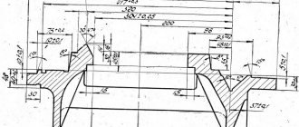
Purpose and design of the tailstock
The tailstock is a device that securely fastens the part when processing in the center or when installing a cutter.
The tailstock has the following characteristics:
- with a quill diameter securing the cutting tool – 70 mm;
- with an internal landing cone of category “Morse 4”;
- with a maximum movement of 15 cm, with one
- division of the dial quill moves by 0.1 mm;
- with a maximum lateral displacement (in both directions) – 15 mm.
Electrical equipment control
The levers of electrical equipment serve as a switch and switch from the network. Workplace lighting is also included. Responsible for the operation of the pump. They control the push-button station to turn the main engine of the machine on and off.
The screw-cutting lathe model 1V62G is a universal machine and is designed to perform a variety of turning operations, including cutting left-handed and right-handed threads: metric, inch, modular, pitch.Depositfiles:
See also:
1V62G. Lathe. Schematic diagram of the electrical equipment of the machine.
| Next > |
Related materials:
- Thyristor converters of the ELL 12ХХХ series for DC motors with permanent magnets. Technical description. Passport. Digital thyristor converters of the 12ХХХ series are designed for precision control of speed or torque in electric drives with DC motors with permanent magnets. Their control is implemented by modern DSP processors and provides electronic…
">ELL 12XXX. Electric drive. Passport, Manual, Instructions, Description, Characteristics.
- Thyristor converters of the ELL 4ХХХ series for DC motors with independent excitation. Technical description. Passport. 4XXX digital thyristor converters are designed for precision control of speed, torque or position of independently excited DC motors for main and feed drives. Depending on the functionality of the…
">ELL 4XXX. Electric drive. Passport, Manual, Instructions, Description, Characteristics.
- Jig boring machine 2431. Datasheet, Characteristics, Diagram, Manual Jig boring machine 2431 Particularly precise jig boring machine 2431 with an optical coordinate reference system is designed to perform finishing operations on parts weighing up to 250 kg, where special accuracy of the relative position of the holes being machined is required and surfaces. The machine is designed for processing…
">2431. Jig boring machine. Passport, Characteristics, Diagram, Manual
- NC-301. CNC system. Passport, Manual, instructions, description, characteristics. CNC NC-301 – High-tech small-sized CNC device for complex high-performance solutions for controlling various types of machine tools up to 4 axes. It is a distributed device that allows you to bring digital inputs/outputs closer to control objects. Main characteristics of CNC NC-301...
">NC-301. CNC system. Passport, Manual, instructions, description, characteristics.
- Radial drilling machine 2N55. Passport, Characteristics, Diagram, Manual Radial drilling machine 2N55 Radial drilling machine 2N55 is intended for wide use in industry. The machine is universal and is used wherever hole processing is required - from the repair shop to large-scale production. The machine can be used to drill in solid material...
">2N55. Radial drilling machine. Passport, Characteristics, Diagram, Manual
The following materials:
- 16D25. Screw-cutting lathe. Machine passport
- 16D20G. Screw-cutting lathe. Machine passport
- 16D20P. Screw-cutting lathe. Machine passport
- 16D20. Screw-cutting lathe. Machine passport
- 16B20. Screw-cutting lathe. Machine passport
Previous materials:
- SAMAT 400. Screw-cutting lathe. Machine passport
- 1B16P. Screw-cutting lathe. Machine passport
- Screw-cutting lathe 16A25. Machine passport. Incomplete Screw-cutting lathe 16A25 The screw-cutting lathe 1A25 is a universal machine and is designed to perform a variety of turning operations, including cutting left-handed and right-handed threads: metric, inch, modular, pitch and Archimedean spiral with a pitch of 3/8", 7 /16", 8, 10 and 12 mm. Screw-cutting lathe passport...
">16A25. Screw-cutting lathe. Machine passport. Incomplete
- 1P371. Turret lathe. Machine passport
- 1P365. Turret lathe. Machine passport
Electrical equipment of a screw-cutting lathe 16B20
Electrical diagram of a 16B20 screw-cutting lathe
Electrical diagram of a 16v20 screw-cutting lathe
- Electrical cabinet, model 1V62G.83V.000
- Supply network: voltage – 380 V, current – three-phase, frequency – 50 Hz
- Control circuit: voltage – 110 V, current – alternating
- Local lighting circuit: voltage – 24 V, current – alternating
- Signaling circuit: voltage – 22 V, current – alternating
- Rated current (sum of rated currents of simultaneously operating electric motors) – 17.6 A
The electrical equipment of the machine is designed to connect power units, lighting and signaling devices to a three-phase alternating current network with a solidly grounded neutral wire, as well as to ensure their protection from overloads, short circuit currents and other factors. All relay contact and other electrical equipment used is simple in design and has proven itself well when working on machine tools. This ensures reliable operation of electrical equipment and the possibility of its maintenance by semi-skilled specialists.
Electrical equipment, with the exception of a few devices, is mounted in electrical cabinet 2 (Figure 8), located on the rear side of the headstock housing.
The power circuit of the machine includes three three-phase asynchronous electric motors, safety devices and switches.
The control circuit includes relay contact and other devices located in the cabinet, as well as a push-button station 11 SB1.1 SB1.2 (Figure 9) for starting and stopping the main drive, limit switches 19 SQ1 for controlling the accelerated motor and limit switches SQ2, SQ3 locking the chuck guard and gearbox cover.
The local lighting circuit EL1 ensures the operation of a machine lamp with a flexible stand and a built-in switch. Illumination 1500 lux.
The signaling circuit includes signal lamps 29 (HL1) and 31 (HL2).
Description of the operation of the electrical circuit
Turning on the input switch QF1 (Figure 12) when there is voltage in the network is accompanied by the lighting of the HL1 lamp.
The start of the electric motor of the main drive M1 is carried out when the input switch QF1 is turned on by pressing the button SB1.1 of the push-button station, which closes the coil circuit of the magnetic starter KM1. In this case, the magnetic system of the starter is triggered and closes its normally open main and auxiliary contacts KM1, that is: the magnetic starter KM1 will switch to self-power, because one of its auxiliary contacts will close the coil power circuit parallel to the SB1.1 button and when the latter is released the circuit will not break; the electric motor of the main drive M1, powered by the power circuit through the closed main contacts of the KM1 starter, will turn on;
The electric motor of the main drive M1 is stopped by pressing the button of the push-button station SB1.2. In this case, the coil circuit of the magnetic starter KM1 will open, it will be de-energized, all contacts of the starter will open, i.e. the electric motor M1 will turn off, the self-supply circuit of the magnetic starter will break.
The rapid movement motor M3 is started by pressing the jog button built into the apron handle and acting on the limit switch SQ1. The normally open contact of the limit switch, when the button is pressed, closes the power circuit of the electromagnet coil of the KM2 starter, which in turn closes the KM2 contacts of the power circuit of the high-speed motor. Switch QF2 is always on.
When the jog button SQ1 is released, the control circuit will open and the starter coil will be de-energized, i.e. the KM2 contacts will open and the M3 electric motor will turn off. Starting and stopping the electric pump M2 is carried out using switch SA1 installed on the front panel of the electrical cabinet.
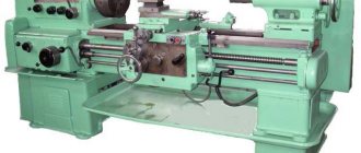
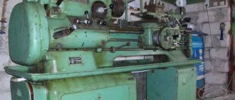
Screw-cutting lathe 1V62G/1000
The equipment of the turning and screw-cutting group is used by repair shops, large production shops and procurement companies. The machine is used as a replacement for the more outdated model 1A62G to perform finishing and semi-finishing work.
Technical features
The 1V62G design is distinguished by the following structural characteristics:
- reliable and durable operation is ensured by a rigid structure made of high-quality steel;
- The machine is equipped with a durable, hardened cast iron box-shaped base, which has a special recess, which makes it possible to process metal workpieces of larger diameter (up to 620 mm) above the base itself;
- the operator can process workpieces of maximum length 1-1.5 mm;
- accuracy class when carrying out screw-cutting operations according to GOST 8-82 - N (normal);
- the 1V62G machine is characterized by an accelerated slide;
- for greater convenience of moving the beam, aerostatic unloading is built into the tailstock;
- due to the universal design, a hydraulic, electromechanical or even pneumatic chuck for fastening workpieces can be mounted on the spindle assembly;
- the equipment has a built-in friction disc clutch, which is switched using a handle on the apron and the headstock of the machine;
- the working tool is supplied with up to 24 speeds, three of which overlap, and 12 of them allow the spindle to rotate in the opposite direction;
- the 1V62G design has three electric motors with a total power of 8.37 kW;
- the mechanism must be connected to a power supply with a voltage of 380 V;
- The 1V62G design is integrated with a double-sided friction disc clutch, which starts and stops, as well as reverses the spindle when the electric motor is turned on.
Note! Turning equipment should only be installed in a closed and heated room.
Operations Performed
1V62G is used to perform a variety of turning operations:
- formation of inch and metric, modular and pitch threads;
- performing conical and cylindrical turning;
- segment;
- drilling;
- trimming ends and other turning works.
Advantages
Thanks to the presence of a centralized lubrication supply system, the cost of purchasing new spare parts is significantly reduced, and the time between overhauls is significantly increased. The need for constant operator contact with dangerous lubrication points is eliminated, and the safety of working at the machine increases. In addition, during work operations the operator is protected by fencing and locking devices.
The equipment performed well when integrated into both small-scale and mass production lines.
The lathe is certified and its structure fully complies with all safety requirements.
Due to the presence of a separate drive of the carriage and caliper, the dynamics are significantly improved and the running speed is increased several times, which also allows you to form inch threads with a diameter of 11 and 19 threads/inch without changing gears.
Equipment
In addition to the machine itself and instructions, the standard package includes:
- thrust center;
- Autonomous coolant supply system;
- spare parts, oiler, set of keys.
The design of the machine can be modernized and the number of operations performed can be expanded. Additionally, you can purchase turning tools and chucks of larger diameter, vibration supports, and a cone ruler with a feed limiter.
Electrical circuit diagram of lathe 1A62G
Electrical circuit of lathe 1a62g
General information about the electrical equipment of the 1A62g lathe
The electrical equipment is designed to connect the machine to a three-phase alternating current network with a solidly grounded or insulated neutral wire.
At the strike, the following AC voltage values are used:
- power circuit – 50 Hz; 380 V
- control circuit – 50 Hz; 380 V
- local lighting circuit – 50 Hz; 24 V
The machine is equipped with two three-phase squirrel-cage asynchronous electric motors. A three-phase squirrel-cage asynchronous electric motor is also installed on the grinding attachment, which is available as an option at a special cost.
The electrical equipment of the machine is mounted mainly on a panel located in the niche of the frame on the rear side of the machine. The niche is closed with a lid with a lock for a special key supplied with the machine.
To ensure high reliability in operation and the possibility of servicing the electrical equipment of the machine by semi-skilled specialists, all relay-contactor equipment has a simple design and has been tested over many years of operation in various conditions.
The workplace is illuminated by a machine lamp mounted on a carriage with a flexible stand and a built-in switch.
Controls of lathe 1A62g
The following controls are located on the front side of the machine:
- three-phase circuit breaker with overcurrent releases, used to connect and disconnect the machine from the power supply network, as well as to protect electrical equipment from short circuit currents
- switch for turning on and off the electric motor of the coolant and lubricating fluid (coolant) pump
- push-button station for starting and stopping the main drive electric motor
A push-button station for starting and stopping the electric motor of the grinding device is installed on the device body.
The local lighting switch is located on the reflector of the incandescent lamp.
Description of the operation of the electrical circuit of the 1A62g lathe
The start of the electric motor of the main drive Ml is carried out after turning on the input circuit breaker AB by pressing the “Start” button of the KnP, which, by closing the circuit of the contactor coil of the magnetic starter KG, switches it to self-power, thereby ensuring the supply of electricity to the electric motor.
Stopping the electric motor of the main drive Ml is carried out by pressing the “Stop” button KS, which opens the circuit of the contactor coil KG, which leads to the opening of the starter contacts and de-energizing the electric motor. The electric motor of the grinding device MZ* is controlled in the same way using the KnP and KnS buttons.
Starting and stopping the electric cooling pump M2 is carried out by a packet switch VP.
The operation of the electric pump M2 is interlocked with the electric motor of the main drive Ml and it can be turned on only after the contacts of the KG starter are closed, i.e. after the electric motor Ml is turned on.
The electric motors of the main drive Ml, the electric cooling pump M2, the grinding device M3* and the transformer TP are protected from short circuit currents by an automatic circuit breaker AB and fuses PR.
Protection of electric motors Ml, M2 and MZ* from long-term overloads is carried out by thermal relays RTG, RTO and RTSh*.
Zero protection of the electrical circuit of the machine, which protects against arbitrary switching on of the electric drive when the power supply is restored after a sudden shutdown, is carried out by the coils of magnetic starters KG and KSh*.
Connecting the electrical equipment of the machine
Connection and maintenance of the machine's electric motors should be carried out in accordance with the instructions for installation and operation of three-phase asynchronous electric motors with a power from 0.6 to 100 kW in accordance with the “Rules for the technical operation of consumer electrical installations and safety regulations for the operation of consumer electrical installations.”
Before connecting the machine, it is necessary to mount the electric motor Ml on the submotor frame and adjust the tension of the pulley belts.