Technical characteristics of the universal lathe 1m63m
| Parameter name | 1m63 | 1m63d | 1m63m |
| Basic technical data of the machine | |||
| Accuracy class according to GOST 8-82 | N | N | N |
| The largest diameter of the workpiece processed above the bed, mm | 630 | 630 | 630 |
| The largest diameter of the workpiece processed above the support, mm | 350 | 350 | 350 |
| Center height, mm | 315 | 315 | 325 |
| Maximum length of the installed RMC part, mm | 1400 | 2800 | 1500 |
| The greatest distance from the axis of the centers to the edge of the tool holder, mm | 320 | 320 | 335 |
| Maximum processing length of a part (without rearranging the cutting slide), mm | 1260 | ||
| Height of the cutter installed in the tool holder, mm | 32 | 32 | 32 |
| Maximum mass of the workpiece, kg | 2000 | ||
| Spindle | |||
| Spindle direct rotation frequency, rpm (number of steps) | 10..1250 (22) | 10..1250 (22) | 12,5..1600 (22) |
| Spindle reverse rotation frequency, rpm (number of steps) | 18..1800 (11) | 18..1800 (11) | 22,4..2240 (11) |
| Number of forward/reverse spindle speeds | 22/ 11 | 22/ 11 | 22/ 11 |
| Spindle hole diameter, mm | 70 | 70 | 80 |
| Center in the spindle according to GOST 13214-79 | Morse 6 | Morse 6 | Morse 6 |
| Spindle end according to GOST 12593-72 | 8m | 8m | 8m |
| Spindle inner taper size | Metric 80 | Metric 80 | Metric 100 |
| Maximum torque on the spindle, kNm | 3,3 | ||
| Spindle braking | There is | There is | There is |
| Caliper. Submissions | |||
| Maximum longitudinal/transverse movement, mm | 1260/ 400 | 2520/ 400 | 1360/ 400 |
| Number of feeds of longitudinal/transverse/cutter slide | 44/ 44/ 44 | 32/ 32/ 32 | 32/ 32/ 32 |
| Limits of working feeds of longitudinal/transverse/cutting slides, mm/rev | 0,064-1,0250,026-0,380,028-0,34 | 0,06-1,40,024-0,5180,019-0,434 | 0,06-1,40,024-0,5180,019-0,434 |
| Limits of increased feed rates of longitudinal/transverse/cutter slides, mm/rev | 1,07-3,20,039..1,180,336..1,0 | 0,24-5,60,096-2,0720,076-1,736 | |
| Limits of metric thread pitches, mm (number of steps) | 1..192 (56) | 1..224 | 1..224 (46) |
| Limits of pitches of inch threads, threads/inch (number of steps) | 24..0,25 (33) | 56..0,25 | 28..0,25 (31) |
| Limits of modular thread pitches, module (number of steps) | 0,5..48(55) | 0,5..112 | 0,25..56 (37) |
| Limits of pitches of pitch threads, pitch diametrical (number of steps) | 96..7/8 (52) | 112..0,5 | 112..0,5 (30) |
| Speed of rapid movements longitudinal/transverse, m/min | 4,5/ 1,6 | 4,5/ 1,6 | 4,5/ 1,6 |
| Maximum cutting force allowed by the feed mechanism, kN | 2,22 | 2,22 | |
| The price of dividing the dial for longitudinal/transverse movement by diameter, mm | 1/ 0,05 | 1/ 0,05 | 1/ 0,05 |
| Movement per dial revolution during longitudinal/lateral movement, mm | 300/ 5 | 300/ 5 | 300/ 5 |
| Cutting slide | |||
| Maximum movement of the cutting slide, mm | 220 | 220 | 220 |
| Maximum angle of rotation of the cutting slide, degrees | ±90° | ±90° | ±90° |
| The cost of dividing the dial when moving the cutting slide, mm | 0,05 | 0,05 | 0,05 |
| Displacement per revolution of the dial when moving the cutting slide, mm | 5 | 5 | 5 |
| Tailstock | |||
| Maximum movement of the quill, mm | 240 | 240 | 240 |
| Transverse displacement of the tailstock, mm | ±10 | ±10 | ±10 |
| Cone for center in quill | Morse 5 | Morse 5 | Morse 5 |
| Electrical equipment of the machine | |||
| Number of electric motors on the machine | 3 | 3 | 3 |
| Main motion electric motor, kW (rpm) | 13 (1460) | 15 (1460) | 18,5 (1465) |
| Electric motor for fast movements, kW (rpm) | 1,1 (1400) | 1,1 (1400) | 1,1 (1400) |
| Coolant pump electric motor, kW (rpm) | 0,12 (2800) | 0,12 (2800) | 0,12 (2800) |
| Dimensions and weight of the machine | |||
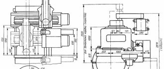
| Machine dimensions (length, width, height), mm | 3530 x 1680 x 1290 | 4950 x 1780 x 1550 | 3655 x 1590 x 1420 |
| Machine weight, kg | 4300 | 5620 | 4400 |
Bibliography
Screw-cutting lathes models 1m63m and 1m63mf101. Operating manual, Tbilisi, 1983
Acherkan N.S. Metal-cutting machines, Volume 1, 1965
Batov V.P. Lathes, 1978
Beletsky D.G. Handbook of a universal turner, 1987
Denezhny P.M., Stiskin G.M., Thor I.E. Turning, 1972. (1k62)
Denezhny P.M., Stiskin G.M., Thor I.E. Turning, 1979. (16k20)
Modzelevsky A. A., Muschinkin A. A., Kedrov S. S., Sobol A. M., Zavgorodniy Yu. P., Lathes, 1973
Pikus M.Yu. A mechanic's guide to machine repair, 1987
Skhirtladze A.G., Novikov V.Yu. Technological equipment for machine-building industries, 1980
Tepinkichiev V.K. Metal cutting machines, 1973
Chernov N.N. Metal cutting machines, 1988
Related Links. Additional Information
Home About the company News Articles Price list Contacts Reference information Download passport Interesting video KPO woodworking machines Manufacturers
MACHINE TOOLS ©™
| The largest diameter of the installed workpiece, mm | |
| - above the bed | 700 |
| - above the caliper | 350 |
| - above the recess in the bed | 900* |
| The largest diameter of the workpiece being processed, mm | |
| - above the bed | 630 |
| - above the caliper | 350 |
| Maximum length of workpiece processed, mm | 750; 1500; 2000; 3000; 4000; 5000; 8000; 10000 |
| Length of the recess in the frame from the end of the spindle flange, mm | 450* |
| Maximum weight of the installed workpiece, kg | 3500 |
| Height of the cutter installed in the tool holder, mm | 32 |
| Headstock spindle end size according to DIN | 11M |
| Internal cone in the spindle headstock (metric) | 115 |
| Number of spindle speed steps | 22 |
| Diameter of cylindrical hole in spindle, mm | 105 |
| Spindle speed limits, rpm | 10—1250 |
| Limits of working feeds, mm/rev | |
| - longitudinal | 0,033—5,6 |
| - transverse | 0,013—2,064 |
| - cutting slides | 0,010—1,76 |
| Limits of pitches of cut threads | |
| — metric, mm | 1— 224 |
| — inch, threads/inch | 28—0,25 |
| - modular, module | 0,25—56 |
| — pitch, pitch dia. | 112—0,5 |
| Accelerated movement of the caliper, mm/min | |
| - longitudinal | 5200 |
| - transverse | 2000 |
| Maximum cutting force, kN | 20 |
| Maximum torque on the spindle, kNm | 3 |
| Main drive power, kW | 15 |
| Overall dimensions (including electrical equipment), mm | |
| - length | 3000; 3740; 4230; 5240; 6240; 7240; 10300; 12420 |
| - width | 1780 |
| - height | 1550 |
| Weight, kg | 4200; 4840; 5100; 5750; 6900; 9000; 11800; 13200 |
www.stanok-machinetools.com
Technical characteristics of the electrical equipment of the machine
Three-phase AC main drive motor:
- type .. A02-6I-4 SPUZ, M101
- power, kW .. 13
- rotation speed at 50 Hz, rpm; .. 1460
- rotation speed at 60 Hz, rpm; .. 1750
Electric motor for high speed carriage
- type .. A02-2I-4 SPUZ M30I
- power, kW .. 1.1
- rotation speed at 50 Hz, rpm; .. 1400
- rotation speed at 60 Hz, rpm; .. 1690
Electric cooling pump motor
- type .. PA-22(XI4-22M)
- power, kW .. 0.12
- rotation speed at 50 Hz, rpm .. 2800
- rotation speed at 60 Hz, rpm .. 3350
- flow, l/min .. 22
Technical characteristics of the lubrication system
- Pump: brand .. C12-54
- type .. gate
- flow, l/min .. 8.2
- Filter:
- Brand .. G41-22
- type .. plate
- nominal filtration fineness, microns .. 120
Electrical equipment and kinematic diagram of the machine
The electrical circuit of the 1M63 machine consists of four electric motors that have the following characteristics.
- A02-61-4 SPU 3 - main electric motor: can be powered by electric current with a frequency of 50 Hz (rotation speed - 1460 rpm) and 60 Hz (rotation speed - 1750 rpm), engine power - 13 kW.
- Х14-22М – electric motor driving the cooling pump: power – 0.12 kW, rotation speed – 2800 rpm (current 50 Hz) and 3350 rpm (60Hz), capacity – 22 liters of coolant per minute.
- A02-21-4 - the engine responsible for the accelerated movements of the lower caliper plate: power - 1.1 kW, rotation speed - 1400 rpm (50 Hz) and 1690 rpm (60 Hz).
- S12-54 is an electric motor responsible for the operation of the vane pump of the lubrication system of a lathe: the lubricant supply capacity is 8.2 liters per minute.
Circuit diagram of 1M63 (click to enlarge)
To ensure that the lubricant reaches the equipment components without impurities, in its pure form, a filter is installed in the pump supplying it, providing a filtration fineness of 120 microns.
The main engine of the 1M63 machine is started using the “Start” buttons, one of which is located on the carriage control panel, and the second next to the feed box, occurs with the clutch turned off. The rotation from this electric motor is transmitted through a V-belt transmission to the friction shaft of the gearbox, with the help of which the rotation speed of the spindle assembly is regulated. This friction shaft is controlled using a special handle. In accordance with the voltage supplied to the main motor, the current in its winding also changes: 380V - 29A, 400V - 27A, 415V - 26.5A, 440V - 25A, 500V - 22A.
The main electric motor of the 1M63 machine, among other things, is also responsible for performing working feeds, and the accelerated movement of the support and carriage is ensured by a separate motor. In order for the support or carriage to start moving, it is necessary to connect electromagnetic type friction clutches, which are located in the inside of the equipment apron.
In total, in the kinematic diagram of the 1M63 machine there are four such couplings, two of them are responsible for the longitudinal movement of the carriage, and the other two are responsible for the movement of the support in the transverse direction. These couplings can be controlled using a special switch located on the apron of the machine, which is installed in one of 5 positions:
- vertical (this position is neutral);
- four inclined, corresponding to the direction of movement of the support or carriage.
Kinematic diagram of 1M63 (click to enlarge)
In addition to the indicated switch, there is another one on the apron of the 1M63 machine, with which you select the required type of work:
- processing the outer surface of a workpiece having a conical configuration;
- processing of internal conical surfaces;
- turning operations.
To prevent the simultaneous activation of electromagnetic couplings and the uterine nut, a limit-type locking switch is installed in the apron of the 1M63 lathe. When the mother nut is turned on, such a switch simply breaks the electrical circuit from which the electromagnetic clutches are powered.
Machine apron (click to enlarge)
Technical and operational characteristics of the 1M63 lathe
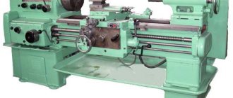
The metal cutting machine model 1M63 was especially popular in the countries of the former Soviet Union. The unit processed workpieces of various diameters. The turning machine was exported to different countries, differing from its competitors in its reliability and ease of use.
Purpose
The 1M63 lathe is designed for processing complex and rounded metal surfaces. In addition, it is used for thread cutting. To process the ends of the workpiece, various cutters, drills, taps, countersinks, and dies can be used. The workpieces to be processed are installed in centers or in a chuck.
Its main advantages are considered to be ease of use, rigidity of support and strong propulsion systems. These advantages determine the operation of turning equipment over a long period of time.
Model markings
The number - the letter index of the screw-cutting unit 1M63 shows:
- number 1 – turning equipment;
- the number 6 indicates that the machine is classified as a metal-cutting machine;
- the letter "M" indicates the generation of the turning device;
- number 3 – the permissible processing radius of the blank is 315 mm.
Among the modified versions of the lathe, the following designation is possible:
- G – unit with a recess in the supporting frame;
- A, M – the turning device contains a mechanical drive of the cutting support;
- B – indicator of machine speed;
- K – installation with copying equipment;
- P – shows the processing accuracy according to “GOST 8-82”;
- F1 – device with digital display installation;
- F2 – screw cutting machine with CNC numerical positioning system;
- F3 – the unit is equipped with continuous CNC.
Modification models
Time and increased demand forces specialists to improve turning equipment. The 1M63 machine, designed for processing metal surfaces, replaced the standard model 163. The units were produced in large volumes. It is not surprising, but at some production sites these turning units have been preserved in proper form and are still in use, despite all the warranty periods that have passed. The 1M63 screw-cutting lathe after some time served as the prototype of the 1M63N model. The 1M63N lathe features improved equipment compared to previous models in the series. The letter "H" indicates that the device provides normal accuracy.
The main differences between 1M63N and previous versions of the series:
- increased power of the main drive;
- increased thread processing speed;
- expanded diameter of the opening in the spindle;
- the ability to process products up to 10 m in length and weighing up to 3.5 tons with increased accuracy;
- impressive service life of turning equipment;
- use of alloy steel in gears;
- increased safety of use.
Among the main modifications of the 1M63 device, the following models are distinguished: 1M63F101, 1M63BG, 1M63M, 1M63N, 1M63NG, 1M63NP.
It is worth noting that the previously popular 1M63 screw-cutting lathe has been discontinued and is no longer available.
How does it work?
Before you begin actual turning work, you must carefully familiarize yourself with the safety precautions and operating rules of the machine.
Failure to follow these instructions will result in consequences. Therefore, if a worker does not have the skill to operate turning equipment, then it is in his best interests to enlist the support of a specialist who will supervise the operation of the installation.
After the turning unit is mounted and connected, it is necessary to first prepare it for operation. The workplace must be clean, without unnecessary parts and tools. To start the drive, press the start button on the feed unit. An additional power button is located on the carriage instrument panel. The clutch must be off.
The movement of the caliper is driven by four friction clutches located in the apron of the device. The apron also has a switch for clamping devices (couplings), two of which provide longitudinal movement, and the other half provide transverse movement. The toggle switch has several modes - neutral and inclined positions, corresponding to the carriage travel vector. The top of the switch has a button that controls the high-speed movement of the caliper.
In situations where the 1M63 screw-cutting lathe is seriously damaged, it must be sent for restoration, having first been put in proper order. Along with the equipment, technical documentation must also be provided to the service in order to resolve the issue of spare parts.
Design features
As it has already turned out, the 1M63 screw-cutting lathe is capable of performing various types of turning, processing cones, and producing threads of any type.
Among the main technical characteristics of the 1M63 are:
- permissible diameter of the part mounted above the main support is 700 mm;
- maximum diameter of the product above the support – 350;
- maximum weight of the blank – 3.5 t;
- spindle unit rotation degree – 22 units;
- diameter of the cylindrical opening in the spindle – 105 mm;
- degree of rotation – from 10 to 1250 rpm;
- cruciform movement of the caliper – 5.2 (longitudinal) and 2 (transverse) m/min;
- power unit power – 15 kW;
- device dimensions – 5,240 x 1,780 x 1,550;
- equipment weight – 5750 kg.
This is what the main technical characteristics of the 1M63 machine look like. If you need to view the complete documentation of the equipment or the 1M63 passport, you can download them for free by clicking on the item “download the passport for the 1M63 machine”. The electrical diagram of the equipment is presented below.
Lunette
What is a lunette? A steady rest is a machine tool that serves as an additional support when processing workpieces. They are intended for the cultivation of round and conical parts.
The steady rest changes with different types of processing. The fixed steady rest is made of cast iron. When installing the structure, it is necessary to take into account the fact that it corresponds to the installation guides. The part is installed using a screw pattern. In cases where the working surface should be fixed in the center, the lunette acts as an auxiliary support.
Photo: steady rest for machine 1M63
Caliper
This element of the machine is intended for fixing cutting tools. It has a cross-shaped design and can move both along the axial guides of the supporting frame and in the perpendicular direction - along the carriages of the lathe. The movement is carried out manually, mechanically; for this purpose, the device has a special mechanism.
Tailstock
This system mechanism is installed to the guides of the supporting frame using 2 strips and 4 bolts. The easy movement of the tailstock along the guides is due to the presence of four radial ball bearings installed in the bridge. To determine the degree of removal of the quill when drilling metal surfaces, a screw dial is mounted, and the axial movement of the quill is carried out using a flywheel.
Cooling system
From the description in the passport it follows that the 1M63 cooling system is a pump mounted in the right cabinet, from where the coolant is supplied to the tool. The spent solution is collected in trays located on the front and back sides of the machine. Next, this mixture again enters the tank of the right cabinet.
Apron
In the machine this mechanism is of a closed type, with a removable front wall. The apron receives rotational movements through a lead screw or roller. Since the 1M63 screw-cutting lathe has electromagnetic couplings, the adjustment of the apron is concentrated in one handle. The rotation vector of the handle coincides with the direction of the feed or carriage stroke. The apron contains an overrunning clutch, which allows you to turn on the speed mode when the working feed is engaged. To avoid the simultaneous launch of the runner and the working screw, the equipment is equipped with an electrical interlock.
Electrical equipment
The screw-cutting lathe is equipped with 4 motors:
- The main engine is A02-6I-4 SPUZ with a rotation rate of up to 1750 rpm.
- Cooling system power unit XI4-22M. Motor speed is 3350 rpm, with a rated power of 0.12 kW. The system is capable of supplying coolant - 22 l/min.
- An engine that promotes accelerated movement of the carriage A02-2I-4. Rotational speed – 1690 rpm, power – 1.1 kW.
- Pump S12-54, used to supply the lubricating mixture - 8.2 l/min. A standard filter model G41-22 is installed on it.
It is worth noting that the main 1M63 engine starts only when the clutch is engaged.
Unit speed and feed unit
The gearbox is located in the left front area of the frame, and its drive pulley rotates due to the operation of the motor. All speeds are regulated according to the principle of stepwise operation of the box. The pulley set in motion starts the operation of numerous components of the gearbox, and the operator controls and regulates the speed by selecting the appropriate speed, of which there are 22 in total. Moreover, the spindle receives 6 maximum speeds from the shaft itself, due to which the efficiency of the unit increases significantly.
All gears, with the help of which the speed of the machine is changed, are made from thermally hardened steel and have high strength indicators. These parts are placed on splined metal rollers, and the shafts, in turn, operate on roller and ball types of bearings. In addition, the speed control and adjustment unit is equipped with two special devices that allow you to change the movement of the caliper to reverse movement and increase the pitch of the manufactured thread by four or sixteen times.
A similar unit is made in a biaxial closed configuration. Due to the operation of the gears and the switching of the feed box levers, the operator can easily control and adjust the work while performing assigned tasks.
The feed box of the 1M63 machine itself is made in a closed version. By using the necessary levers and replacing special gears, if necessary, it is possible to fine-tune the feed process for producing a normal range of different types of threads, as well as obtaining the required feeds when turning various parts on a given lathe. And to create high-precision and specialized individual threads, it is better to take advantage of the opportunity to switch to direct screw engagement.
An incredible number of modification models were created based on the 1M63, giving this turning unit special significance. Despite the new generation of modern machines, the 1M63 installation continues to be installed at many manufacturing enterprises in the country, processing a huge number of workpieces every day.
Passport
Download the passport of the screw-cutting lathe 1M63
oxmetall.ru
Gearboxes and feeds
The gearbox is located on the left side of the base of the device. Rotation from an electric motor is transmitted to its friction wheel, due to which the gears in the box are activated. There are 22 speeds in total, the selection of which is carried out by switching them sequentially.
The frequencies of the main shaft mechanisms are selected using gears made of high-quality heat-treated steel. The gears are mounted on special steel rollers rotating on roller and ball bearings. The box contains two devices that increase the thread pitch and reverse the movement of the tool holder.
The feed box has a biaxial layout, which increases its operating efficiency. Its adjustment is carried out using switch handles and gears. Only when the spindle is turned on directly, using a separate set of gears, is it possible to cut special threads that are particularly accurate.
The rotation is supplied from the gearbox to the feed shaft by means of a guitar. By combining replaceable gears, you can configure the installation for cutting different threads.
Technical characteristics of the screw-cutting lathe
The first machines were created by specialists from the Ryazan plant. The machine gained popularity due to its technical characteristics and many enterprises began to use it.
The height of the centers of the 1M63 machine is thirty-one and a half centimeters. You can work on it with parts up to one hundred and forty centimeters long. The spindle rotates from 10 to 1250 rpm in forward motion, and in reverse up to 1800 rpm.
The machine has a through hole with a diameter of seven centimeters. The cutting head can accommodate four turning tools at one time.
Machine device
Installed on the left end of the working base of the device and represents the gearbox. The main working shaft is located on two supports: the front one – a bearing with two rows of tapered rollers; rear – bearing with one row of tapered rollers and springs.
Caliper
Cross structure moving in axial and perpendicular directions. Movement is carried out mechanically or manually. The tool holder is equipped with a mechanism that ensures its accelerated movement.
Rear node
It is installed on the guides of the working base of the device, moves on four bearings and is fixed on the guides with two strips and four bolts. The perpendicular displacement of the unit is carried out by two screws and one nut built into the bridge.
Video: turning work on the 1M63 machine
Republished by Blog Post Promoter
Preparing the 1M63.01 machine for launch.
Alignment of the installation of the machine in a horizontal plane is carried out using a level installed in the middle part of the support parallel and perpendicular to the axis of the centers (the foundation bolts must not be tightened). In any position of the carriage, the level deviation should not exceed 0.04 mm per 1000 mm.
Having familiarized yourself with the instructions set out in the sections immediately following this, you can, in accordance with the sequence recommended below, begin to prepare the 1M63.01 lathe for start-up.
Perform all operations related to preparing the 1M63.01 machine for startup, set out in section 6 “Machine lubrication,” and fill the base chip collector located under the bed with coolant.
Connect according to the instructions in Section 7 “Electrical Equipment”. the machine to the grounding circuit and, after checking the correspondence of the network voltage and the electrical equipment of the machine, connect it to the electrical network.
After familiarizing yourself with the purpose of the controls (section, check by hand the operation of all machine mechanisms. The spindle rotation switch lever must be set to the neutral position.
You should be aware that due to the presence of locking devices, the 1M63.01 machine cannot be turned on:
- with the control cabinet door open;
- with the cover of replaceable gears open;
- with the cartridge guard cover folded back.
A description of blocking devices is placed in section 7 “Electrical equipment”.
By pressing the black “Start” button 5 (Fig. 4), turn on the main drive electric motor.
ATTENTION! It is imperative to check the operation of the centralized lubrication system of the spindle head of the 1M63.01 machine and the feed box using the oil indicator. If the oil indicator does not rotate, operation of the machine is unacceptable .
The operation of the lubrication pump can be monitored through a peephole located on the front of the headstock.
Using a switch, check the operation of the coolant pump motor.
After completing these operations, the machine is ready to start.
1M63D universal screw-cutting lathe. Purpose, scope
The 1m63d screw-cutting lathe (beginning of serial production in 1983) replaced the model. In 1986, the 1m63d machine was replaced by a more advanced model.
Screw-cutting lathes 163 series are one of the most widespread in the territory of the former USSR, designed for processing parts of medium and large sizes, in conditions of single and small-scale production. The machine can perform external and internal turning, including turning cones, boring, drilling and threading (metric, modular, inch and pitch).
Modifications of the 1M63 screw-cutting lathe
1M63 - the next generation of the 163 series, the machine replaced the 163 model, production began in 1968.
1M63F306 – CNC screw-cutting lathe, serial production began in 1973.
1M63F101 – a screw-cutting lathe with a digital display that provides a readout of the lateral movement of the support, serial production began in 1976.
1M63B, 1M63BG, 1M63BF101 – high-speed screw-cutting lathes with increased power.
1M63D, 1M63DF101 – screw-cutting lathes, Tbilisi, 1983.
1M63M, 1M63MF101 – screw-cutting lathes with increased power, Tbilisi, 1986.
1M63MF30 – CNC lathe Electronics NTs-31, Tbilisi.
1M63MS5 – screw-cutting lathe 163 series, Tbilisi, 1991.
Main technical characteristics of the 1M63D screw-cutting lathe
Manufacturer: Tbilisi Machine Tool Plant named after. Kirov.
The planned period for the installation series is 1983.
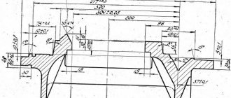
- The largest diameter of a Disk-type workpiece processed above the bed is Ø 630 mm
- The largest diameter of the Shaft type workpiece processed above the support is Ø 350 mm
- Distance between centers – 1400 mm
- Center height – 315 mm
- Electric motor power – 15 kW
- Total weight of the machine – 4.3 t
Spindle of screw-cutting lathe 1M63D
- Spindle end - according to GOST 12593 (Spindle ends are flanged for a rotary washer and clamping device flanges)
- Nominal cone diameter D = 139.719 mm, nominal spindle end size – 8
- Internal (tool) spindle cone – Morse 6
- The diameter of the through hole in the spindle is Ø 70 mm
- Limits of direct spindle revolutions per minute (22 steps) – 12.5..1600 rpm
- Limits of spindle reverse revolutions per minute (11 steps) – 22.4..2240 rpm
- Standard chuck diameter – Ø 400 mm
Feeds and threads of screw-cutting lathe 1M63D
- Limits of longitudinal feeds – 0.06..1.4 mm/rev
- Transverse feed limits – 0.024..0.518 mm/rev
- Feed limits of the cutting slide – 0.019..0.434 mm/rev
- Limits of metric thread pitches – 1..124 mm
- Limits of modular thread pitches – 0.25..56 modules
- Limits of inch thread pitches – 28..1/4 threads per inch
- Limits of pitches of pitch threads – 112..0.5 pitches
The technical characteristics and rigidity of the design of the machine bed, carriage, and spindle allow full use of the capabilities of working at high cutting speeds using cutters made of high-speed steel or equipped with carbide plates when processing parts made of ferrous and non-ferrous metals.
The machine support has a mechanical movement of the upper part, which allows turning long cones. Turning of short tapers is also carried out by moving the upper part of the support.
Changing the feed rates and adjusting the pitch of the thread being cut is carried out by switching the gears of the feed box and adjusting the set of interchangeable gears.
The support has rapid movement in the longitudinal and transverse directions, which is carried out by an individual electric motor.
Lathe designation
In 1937, ENIMS developed a type (nomenclature of types and sizes) of machine tools, including the adoption of a unified system of machine symbols.
1
– lathe (group number according to ENIMS classification)
M
– generation of the machine or designation of the manufacturer:
6
– subgroup number (1, 2, 3, 4, 5, 6, 7, 8, 9) according to the ENIMS classification (6 – screw-cutting lathe)
3
– height of centers above the bed (1, 2, 3, 4, 5) (2 – height of centers 315 mm)
Letters at the end of the model designation:
G
– a machine with a recess in the bed
A, M
– a machine with a mechanical drive of the upper (cutting) support. Available upon special order
B
– high-speed machine
D
- a machine manufactured by the Tbilisi Machine Tool Plant named after. Kirov
TO
– machine with copying device
P
– machine accuracy – (n, p, v, a, s) according to GOST 8-82 (P – increased accuracy)
F1
– a machine with a digital display device (DRO) and preset of coordinates
F2
– machine with CNC positional numerical control system
F3
– machine with contour (continuous) CNC system
The 1M63N machine is time-tested.
This screw-cutting lathe of normal accuracy 1m63N is designed to perform various turning operations, such as turning cylindrical surfaces, trimming ends, turning grooves, cutting off a machined part, boring internal cylindrical surfaces, drilling, countersinking, reaming, processing conical surfaces, as well as for cutting metric, inch and pitch threads. High drive power and rigidity of the machine, a wide range of spindle speeds and feeds allow full use of the capabilities of progressive tools when processing various materials.
Technical characteristics 1M63N Largest diameter of the workpiece, mm:
installed above the bed 700 processed above the bed 630 processed above the support 350 installed above the recess of the bed 900*
Maximum length of the workpiece being processed, mm 1500,2000,3000,4000,5000,8000,10000 Length of the recess in the frame from the end of the spindle flange, mm 450*
Headstock spindle end size according to DIN 11M Number of spindle speed stages 22 Diameter of cylindrical hole in spindle, mm 105 Spindle speed limits, rpm 10…1250
Limits of caliper working feeds, mm/rev:
longitudinal 0.033...5.6 transverse 0.013...2.064 cutter slide 0.010...1.76
Limits of pitches of cut threads:
metric, mm 1…224 inch, number of threads per 1″ 28-0.25 modular, module 0.25-56 pitch, pitch 112…0.5
Accelerated movement of the caliper, mm/min:
longitudinal 5.2 transverse 2
Maximum weight of the workpiece being installed, kg 3500 Main movement drive power, kW 15
Overall dimensions of the machine 1М63Н, mm:
length 3750,4200,5250,6230,7250,10300,12470 width 1780 height 1550
Weight of screw-cutting lathe 1M63N, kg 4840,5100,5750,6530,9000,11800,13200 * For machines with GAP.
Design Features
- The rigidity, vibration resistance and temperature stability of the technological system make it possible to obtain the necessary processing accuracy.
- The two-prism guides of the frame, combined with the high reliability of other components, ensure a long service life of the machine while maintaining the original accuracy.
- The frequency of reverse spindle rotation is 1.3 times higher than direct spindle rotation, which reduces thread processing time.
- Turning of long cones is carried out by simultaneous longitudinal feed of the support and feed of the cutting slide with their corresponding rotation.
- Turning of short cones is carried out by mechanical feeding of a cutting slide, turned to the desired angle.
- The feed box has a high rigidity kinematic chain; all power gears of the kinematic chain are made of alloy steel, hardened and ground.
- Guards for the cutting area and chuck, electrical and mechanical interlocks guarantee safe operation of the machine.
Design and operation of the main components of the machine
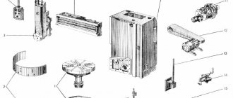
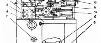
The machine consists of the following main components: Bed 1, feed box 2, replacement wheels 3, headstock 4 with spindle 6, electrical cabinet 5, apron 7 and support 9, movable 8 and fixed 10 rests, tailstock 11, electric motor for rapid movement support 13, support mechanism for the lead screw and shaft 14. Bed.
The bed is the basic assembly unit on which other assembly units are mounted. The bed is solid cast with stands, has two prismatic guides for the carriage and two for the tailstock, one of which is flat. Inside the frame there are inclined hatches (windows) for removing chips and coolant. The right cabinet contains a tank with emulsion and an electric pump. The main drive electric motor is mounted on the left pedestal at the back. Headstock. The headstock is installed on the left head part of the bed. All gears of the kinematic chain are mounted on shafts and spindles, made of chromium steel, hardened and ground. The shafts are mounted on rolling bearings. The spindle with a through hole and internal cones has two supports. The front support is a double-row bearing with short cylindrical rollers. The rear support is an angular contact bearing paired with a thrust ball bearing. Changing the spindle rotation speed is achieved by moving gear blocks along splined shafts using two handles located on the front wall. Direct and reverse rotation of the spindle is carried out by a friction mechanical clutch, and braking is carried out by an electromagnetic clutch. Tailstock. The tailstock moves along the bed guides on four radial ball bearings installed in the bridge. The headstock is secured to the frame guides using two strips with four bolts. The transverse displacement of the headstock body relative to the bridge is carried out using two screws and a nut installed in the bridge. The quill is moved by a handwheel. Caliper. The support of the cross design has longitudinal movement along the prismatic guides of the frame and transverse movement along the carriage guides. Movement can be carried out manually or mechanically. There is a mechanism for quickly moving the caliper. The rotating part of the caliper has guides for moving the upper part of the caliper with the cutting head. Apron. Closed apron with a removable front wall (lid). The movement of the caliper is transmitted through the apron from the lead screw or lead shaft. The apron mechanism is equipped with four electromagnetic clutches, which made it possible to concentrate control on one handle, and the directions of activation of the handle coincide with the direction of feed movement. The same handle has a built-in caliper fast travel button. Thanks to the presence of an overrunning clutch in the apron, high speed can be activated when the feed is on. Feed box . The feed box has two longitudinal bores in which shafts are mounted on rolling bearings. The gears are made of chrome steel and hardened. Adjustable gears make it possible to cut two types of threads, metric and inch, without rearranging replacement gears. When rearranging replaceable gears, it is possible to cut two more types of threads - modular and pitch. Replaceable gears . Replaceable gears located on the wall of the headstock housing allow for feeding and cutting metric, inch, modular and pitch threads in accordance with the passport data. Lunettes . For processing non-rigid parts with a diameter of 20 to 150 mm, the machine is equipped with movable and fixed rests. The steady rests are equipped with replaceable rollers and crackers, installed depending on the operating conditions. Cooling. From the electric pump installed in the right cabinet of the frame, the coolant is supplied to the tool through a pipeline and hose, and then flows into two troughs installed in front and behind the machine, from where it returns to the electric pump tank.
The troughs and tank must be cleaned at least once a month. You can get more detailed information here https://www.td-osz.ru/ beconected.com
Description of work
Before starting work with equipment such as a lathe, it is imperative to study the operating instructions, as well as familiarize yourself with the safety rules.
Neglecting them can harm your health. If you do not have a lathe education or special training, then it is in your best interests not to operate the machine without the strict supervision of a specialist.
After assembling and connecting the unit, you also need to clean it and prepare it for use. Having tools and parts scattered around the workplace is unacceptable. The drive is turned on by the start button, which can be found near the feed box. There is another start button, which is located on the dashboard of the carriage. When starting the engine, the clutch must be turned off!
To set the caliper (carriage) in motion, you need to connect the friction clutches located in the apron. Four clutches, one half of which provide longitudinal movement, the other half transverse, are controlled by a switch located on the apron. The switch has 1 vertical (neutral) position and 4 inclined positions, according to the direction of movement of the caliper. The switch head has a button that turns on the high-speed movement of the caliper.
In the event of a serious breakdown, the machine should be sent for repair. Before doing this, be sure to clean the unit from dirt and chips and drain the liquids. Together with the machine, a technical passport, a technical inspection certificate and a list of assembled spare parts, which are sent dismantled from the machine, must be sent. If any spare parts are missing, the repair plant will produce them for a fee.
Electrical equipment of the machine 1M63.01
To ensure high reliability in operation and maintenance of the electrical equipment of the 1M63.01 machine by semi-skilled specialists, all relay-contactor equipment and other electrical equipment have a simple design and have been tested over many years of operation in various conditions.
The electrical equipment of the 1M63.01 machine (with the exception of several devices) is mounted in a control cabinet located on the rear side of the machine.
The electrical equipment of the 1M63.01 machine is designed for connection to a three-phase alternating current network with a solidly grounded or insulated neutral wire.
The electrical connection and the power cables used must comply with regulations. The voltage and frequency in the electrical network must correspond to the data on the machine nameplate. The fuse should be 25A.
Use connecting cables only with the designation H07RN-F.
Electrical connections and repairs must be carried out by qualified electricians.
The electrical connection is made to the terminal blocks in the electrical cabinet at the rear of the machine.
Safety instructions
The 1M63.01 machine must be securely connected to the workshop grounding device (circuit).
The electrical resistance measured between the ground screw and any metal part of the machine that may become live as a result of insulation breakdown should not exceed 0.1 ohm.
IT IS STRICTLY PROHIBITED to work with an open terminal box and control cabinet!
A safety light-signal device is installed in the control cabinet, indicating the presence of voltage between the output terminals of the input circuit breaker and the neutral wire.
Controls of the 1M63B screw-cutting lathe and their purpose
- Spindle speed setting handle
- Handle for setting normal and increased thread pitch
- Handle for setting right and left threads and feeds
- Spindle speed setting handle
- Handle of the plunger pump for lubrication of the guides of the longitudinal movement of the caliper and the lead screw
- Pull button for turning on the mechanical transverse feed of the caliper.
- Handle for turning on the mechanical movement of the cutting sled
- Handle for turning and fastening the cutting head
- Light switch
- Manual cross feed handle
- Button for enabling the rapid movement of cynnopta
- Cross switch for controlling working and accelerated movements of the caliper
- Handle for manual movement of the cutting slide
- Tailstock quill fastening handle
- Tailstock quill moving handle
- Clutch control handle
- Lead screw nut engagement handle
- Cooling pump switch
- Caliper mode switch
- Control station for turning on and off the main drive
- Flywheel for manual longitudinal movement of the caliper
- Pull button for turning on the rack and pinion gear for longitudinal movement of the caliper
- Clutch control handle
- Control station for turning on and off the main drive
- Lead screw or lead shaft activation handle
- Handles for setting the feed rate or thread pitch
- Handles for setting the feed rate or thread pitch
- Feed and thread adjustment handle
- Signal lamp for voltage presence
- Signal lamp for turning on the electromagnetic brake
- Load indicator
- Input switch