Sooner or later, depending on the intensity of work, a self-centering three-jaw chuck loses its accuracy due to wear of the rubbing parts (spiral, jaw guides in the chuck body, the jaws themselves). As a result of this, the chuck begins to “beat,” i.e., the axis of the cylindrical testing mandrel clamped into the chuck (or part) does not coincide with the axis of rotation of the lathe spindle. There is beating of the surface of the part when it rotates. This can affect the appearance of “blackness” when processing a workpiece with a minimum allowance for processing, and in other cases when it is necessary to maintain the alignment of the shaft journals when processing without the participation of machine centers.
The meaning of this operation is that it is necessary to align the axis of the working surfaces of the cams with the axis of rotation of the spindle. It would seem very simple to machine (bore) the chuck jaws directly on the machine along the working surfaces. This is true, but there is no point in boring the cams in a free state when they are not clamped - the runout will not be eliminated. The cams must be bored in their working position, that is, in the clamped position. There are several options for clamping the jaws so that the boring cutter can pass inside them. One of them is to use an insert ring on which the cams are loaded.
It is done this way: a cylinder is clamped into the chuck, the diameter of which determines the size of the hole into which the boring cutter will fit. On one of the steps of the cams a groove is cut for the bearing race. The depth of the groove corresponds to the width of the cage. The cylinder is removed, the bearing race is inserted into the grooves and clamped (not unclamped, but clamped). It is not scary if the ring is deformed when clamped; the main thing is that all the gaps in the cartridge joints are selected. In this position, the cams are bored. The boring radius of the cams should be as small as possible so as not to worsen the clamping conditions for small-diameter parts. Transverse grooves, which become less deep after boring the cams, can be cut without opening the cams after boring them. If the side edges of the jaws prevent them from coming together when clamping a small-diameter part, the jaws can be removed from the chuck body and milled with a milling cutter with carbide inserts.
Each cam must always be in its groove. The cam and groove must be marked accordingly and after cleaning the cartridge or repairing it, assembly must proceed according to the marks.
In general, this method can be used on all, not just universal, lathes, where self-centering chucks are installed and it is possible to install a boring cutter.
- เผยแพร่เมื่อ 8 พ.ค. 2017
- วิทยาศาสตร์และเทคโนโลยี
Boring
First, we recommend sanding the parts of the cartridge that are important for the job, after removing it. Only after this we do the boring. We need to install the jaws so that the diameter between them matches the diameter of the chuck hole. We clamp the ring with our fists, while the cutter should calmly move outward. We take two cutters: one for boring grooves (so that all chips and other production waste are freely removed from the hole), and the second for boring planes. First, we put the first cutter to work. It is necessary to select a machine speed with a low rpm. We choose the cutting depth at our own discretion, the main thing is that the working surface of the cams remains within the permissible area. After this, we change the cutter to a second one (for planes). The contact should be over the entire working area of the jaws, so first turn on low speed and make sure that the cutter equally touches all three (if you have a three-jaw chuck) sides. At the end, we bore the cams with a cone: this way the workpiece will be better secured by them.
Boring and grinding lathe chuck jaws: procedure
Wear of the rubbing parts of a lathe chuck is a typical problem for a turner. It leads to workpiece beating and poor processing quality. In this case, it is not necessary to replace the part with a new one. Sometimes it is enough to simply bore the jaws of the lathe chuck.
Boring is also required to give the required dimensions to non-hardened (raw) jaws, which are usually used to clamp workpieces with non-standard geometry.
Due to high speeds and loads, the lathe chuck periodically wears out and accuracy is lost. The machine operates at high speeds. As a result, there is a loss of cylindrical girth of the workpiece due to uneven wear of the clamping surfaces of the cams. This leads to beating of the processed blank and defects due to the fact that the part does not meet the declared dimensions and quality requirements. And in the long term, it can lead to breakdown of the main components of the machine.
The main purpose of boring is to align the axis of the working surfaces of the chuck jaws with the axis of rotation of the spindle.
Types of turning jaws
Lathe chuck jaws come in several types.
used for clamping a workpiece from the outside with a shaft or on the inside for a workpiece with a hole.
necessary for clamping the workpiece from the outside. They are designed for turning hollow parts.
are used when processing something large-scale: when the length of the workpiece is too long or the diameter size is large (and in this case it does not matter how long the workpiece itself is).
consist of a rail on which an overhead cam is attached.
Regardless of the type of cams, recommendations for boring them are universal.
How to bore the jaws correctly?
Professional boring is carried out in several stages. If you perform each of them efficiently, following all technical recommendations, then the equipment will serve you for a long time.
To bore the jaws, follow the following procedure:
1. Dismantling the lathe chuck.
2. Processing with sandpaper.
3. Boring of the jaws.
4. Grinding the cams (if necessary).
We'll tell you more about it below.
Removing the lathe chuck
The first step is to dismantle the lathe chuck. Otherwise, you simply will not be able to eliminate the runout of the part and correctly align all the necessary axes. If the chuck is not clamped on the machine, the malfunction will persist.
After dismantling, remove the cams and clean them. The next step is to check the runout.
Sandpaper treatment
If the wear is slight, it is enough to treat the cartridge part first with coarse-grained and then with fine-grained sandpaper. Sometimes this method helps restore the cylindrical girth.
However, with a large degree of wear on the cams, you will have to resort to full boring.
1. First, secure the jaws so that the diameter between them matches the size of the lathe chuck hole.
2. Clamp the ring with your fists so that it can move freely.
3. For boring, you will need two cutters: one for boring grooves (so that chips and production waste can be freely removed from the hole), and the second for developing planes.
4. Start with low speeds and gradually increase the speed, set the optimal rotation mode.
5. We start boring with the first cutter, choosing the optimal groove depth so that the surface of the cams is within the permissible area.
6. Then we use a cutter to disassemble the planes. It must be secured so that contact occurs along the entire working plane of the fists.
7. At the end, we make a conical boring of the cams, so that in the future the workpiece being processed can be firmly attached to them, making the grip reliable and safe.
The final stage of boring the cams is grinding, which is carried out only if it is really necessary. How can I check this? Clamp the metal shaft with the jaws and start the machine. If there is runout, you will have to grind it.
To do this, you need to process the inside, holding the ring with them so that the cams do not unwind spontaneously.
The easiest method is grinding using a cutter with a special stone.
If you follow the above procedure completely, the cams will serve you for a long time.
You can choose high-quality clamping jaws SMW-Autoblok (Germany) in our catalog.
Rules for working with a file
In order to perform the tasks for which the device was created, it is necessary to apply its grooved zone with little force to the area that is to be filed. Then, without loosening the pressure, set it in motion. The teeth of the tool's notch will begin to remove the top from the workpiece. This action is defined by the technical term “layer-by-layer cutting of material from the surface.” The quality of the cut is the result of the correct choice of the notch number, and productivity is determined by the pressing force and the frequency of tool movements along the workpiece. The final processing of the part is carried out with a file or velvet file. Wood processing is done with a rasp.
A file is a hand tool. To start working with it, you need to perform the following operations:
- Check the serviceability of the tool. The handle should fit tightly, without play.
- Familiarize yourself with the safety rules and strictly follow them.
- Firmly secure the workpiece in appropriate devices, for example, in a vice or press it to the workbench with a clamp. It is desirable that the surface to be processed is horizontal. The part should protrude above the surface of the vise jaws by approximately 5 - 8 mm.
- If the worker is right-handed, then he takes the file by the handle in his right hand, places the tool with the working part on the area of the part intended for processing, gently presses it to the part with his left hand and begins horizontal forward-return movements back and forth. When moving forward, you need to press on the handle and toe. The direction of movement is approximately 45 degrees to the front of the workpiece. For each forward movement, the file removes a certain amount of material from it. Using a brush (cord) made of hard wire, it is necessary to remove chips from the gear field. To prevent clogging of the notch with non-ferrous metal filings, experts advise rubbing the tool with chalk before starting work.
- If the plane of the part is processed with a flat file, then after each working pass the tool should be moved to the side perpendicular to the working stroke. This way the entire treatment area will be covered.
- It is necessary to ensure that the tool moves without distortion, otherwise scratches and grooves will appear on the part.
- If the task is to process a narrow strip between two walls, then care must be taken not to damage the restricted area.
- When reaming a round or shaped hole, you must also monitor the change in its shape as a result of the work of a round or square file.
Experienced craftsmen often upgrade the tool, customizing it to their taste and specific tasks. They change the length, sharpen the end, make a more comfortable handle.
A file is used to refine a part that has been turned on a lathe. Using a hand tool, the grooves from the cutter are removed, grooves are formed, and chamfers are removed.
Boring
To carry out the procedure, it is necessary to dismantle the cartridge and treat it with sandpaper. On the one hand, it may seem that the chuck knuckles can be easily machined directly on the machine, but this is not the case. Boring the jaws of a lathe chuck, which are in a free state, without clamping them will not lead to any result, and the runout cannot be eliminated. Parts can only be bored when clamped, because this is their working position. Therefore, boring of the cams is carried out in the following order:
- the cams are installed, matching their diameter to the hole in the lathe chuck;
- the ring is clamped using cams so that it can move freely;
- we use one cutter for boring grooves so that chips and waste can be easily removed from the hole, the second for developing planes;
- the optimal rotation mode is found, starting at low speed. The first cutter is used first, selecting the required groove depth so that the surface of the cams is within the allowable area;
- the cutter for the planes is launched so that contact occurs along the entire working plane of the fists. To do this, the machine is started at low speed and the contact of the cutter on all sides is observed;
- The cams are tapered so that the workpiece being processed can be firmly attached to them, making the grip reliable and safe.
Wear of the rubbing parts of a lathe chuck is a typical problem for a turner. It leads to workpiece beating and poor processing quality. In this case, it is not necessary to replace the cams with new ones. Sometimes it is enough to simply bore the jaws of the lathe chuck.
Boring is also required to give the required dimensions to non-hardened (raw) jaws, which are usually used to clamp workpieces with non-standard geometry.
Due to high speeds and loads, the lathe chuck periodically wears out and accuracy is lost. The machine operates at high speeds. As a result, there is a loss of cylindrical girth of the workpiece due to uneven wear of the clamping surfaces of the cams. This leads to beating of the processed blank and defects due to the fact that the part does not meet the declared dimensions and quality requirements. And in the long term, it can lead to breakdown of the main components of the machine.
The main purpose of boring is to align the axis of the working surfaces of the chuck jaws with the axis of rotation of the spindle.
Types of turning jaws
Lathe chuck jaws come in several types.
Direct
used for clamping a workpiece from the outside with a shaft or on the inside for a workpiece with a hole.
Reverse
necessary for clamping the workpiece from the outside. They are designed for turning hollow parts.
Invoices
are used when processing something large-scale: when the length of the workpiece is too long or the diameter size is large (and in this case it does not matter how long the workpiece itself is).
Prefabricated
consist of a rail on which an overhead cam is attached.
Regardless of the type of cams, recommendations for boring them are universal.
How to bore the jaws correctly?
Professional boring is carried out in several stages. If you perform each of them efficiently, following all technical recommendations, then the equipment will serve you for a long time.
To bore the jaws, follow the following procedure:
1. Processing with sandpaper.
2. Boring of the jaws.
3. Grinding the cams (if necessary).
We'll tell you more about everything below.
Sandpaper treatment
If the wear is slight, it is enough to treat the chuck jaws first with coarse-grained and then with fine-grained sandpaper. Sometimes this method helps restore the cylindrical girth.
However, with a large degree of wear on the cams, you will have to resort to full boring.
Boring
1. First, secure the jaws so that the diameter between them matches the size of the lathe chuck hole.
2. Clamp the ring with your fists so that it can move freely.
3. For boring, you will need two cutters: one for boring grooves (so that chips and production waste can be freely removed from the hole), and the second for developing planes.
4. Start with low speeds and gradually increase the speed, set the optimal rotation mode.
5. We start boring with the first cutter, choosing the optimal groove depth so that the surface of the cams is within the permissible area.
6. Then we use a cutter to disassemble the planes. It must be secured so that contact occurs along the entire working plane of the fists.
7. At the end, we make a conical boring of the cams, so that in the future the workpiece being processed can be firmly attached to them, making the grip reliable and safe.
Grinding
The final stage of boring the cams is grinding, which is carried out only if it is really necessary. How can I check this? Clamp the metal shaft with the jaws and start the machine. If there is runout, you will have to grind it.
To do this, you need to process the inside, holding the ring with them so that the cams do not unwind spontaneously.
The easiest method is grinding using a cutter with a special stone.
If you follow the above procedure completely, the cams will serve you for a long time.
You can choose high-quality clamping jaws SMW-Autoblok (Germany) in our catalog.
Dimensions
The common dimensions for direct and reverse cams are:
- the presence of identical sizes in terms of basic parameters - length, width, height, comb pitch, step sizes, etc.;
- are unified in their design, however, the set of jaws of one cartridge is not identical to the set of another (substantial modification is always required);
- cams with dimensional errors do not fasten the part correctly. At the same time, one of them does not participate in the clamping, forming a gap between the prism and the surface of the part, which is easily checked with a flashlight beam;
- wear on the surfaces of the disk spiral and the cams and racks significantly changes the characteristics of the clamping forces and the accuracy of the rotation part;
- inaccuracy in the linear dimensions of contact surfaces, for example, slats and pads, leads to displacement of the working surfaces, and hence, either excessive clamping forces or their absence at all, which is unacceptable and dangerous when working with such devices.
Restoring the geometry of the lathe chuck jaws
On 06/26/2020 at 08:22, 2Thomas53 said:
the actual question is this: as a result of numerous borings, straight cams began to clamp the workpiece from 7mm and above.
and what's the problem? After all, from 7mm they clamp normally? Well, let it be...
In my opinion, the cams are almost consumables. More precisely, “a very replaceable nozzle.” Like any piece of iron that is directly involved in contact with the workpiece, there must be many and different pieces of these pieces of iron.
In addition, there were topics here, the boring of the cams was discussed - how, how, how correctly.... And there it slipped out that ideally the blades are bored to the size of the workpiece being clamped - this way they spoil it less and hold it more tightly. Which, in general, is not without meaning, since it is obvious that uncut cams clamping small diameters are quite sharp and the contact area of the cams is small. Relative to the surface area of a thin workpiece, they are of course a decent area, but if you take a workpiece with a larger diameter, then this area becomes indecently small. And this is where more bored cams come to the rescue.
This is especially important if the material is soft and pliable... sharp fists will leave a significant imprint there. And those bored to a large radius may not leave any noticeable marks at all.
Combs are a good invention. Since the base of the cam does not interact with the workpiece, but only ensures the rigidity and accuracy of the movement of the cams during operation of the chuck, there is no point in having a lot of them. But the sponges on the combs can be easily and quickly changed in batches for each task.
Well, the tasks of cams are not simple. Otherwise, in addition to the usual direct and reverse cams, we would not have come across all sorts of different ones, including very cleverly shaped ones.
It seemed to me that direct and reverse cams of a standard shape (three steps) are considered to be quite universal (not to be confused with universal ones, which from 200 rounds and above are those that are reversed) and these cams are most often set. Rectangular-shaped cams are most often gray - as far as I understand, this shape is intended as a blank - from it you can machine cams of any shape convenient for a particular job.
Well, don’t forget about the cones in the spindles. They are there for a reason. In this case, in the 160th chuck, clamping a workpiece less than 7mm, well, in my opinion, this is somehow not entirely correct... with such sizes of chucks and jaws, they will only get in the way... I would clamp this into a collet chuck in the spindle. It holds securely and, most importantly, accurately.
ZY You don’t need to listen to me anymore - I’m not a turner, I’m just learning
On 06/26/2020 at 17:15, 2Thomas53 said:
and my age (67), having suffered a stroke, hints at thinking about something else, more sublime, if I could stand the night and hold out for the day...
The shark breathes when it moves. Without moving, she suffocates and dies.
The horses are dying from work. And a person lives while he works. Without work, it withers and becomes fertilizer.
So forget about the sublime.
Don’t be distracted by it, it won’t get away from you. Modified on June 28, 2021 by user Kuvaldych
How to squish it correctly?
To properly bore the cartridge, you must follow the sequence of actions. Professional boring is carried out in several stages, each of which must be performed with high quality and in accordance with all technical requirements.
Dismantling
First of all, it is necessary to dismantle the cartridge. Otherwise, it will not be possible to get rid of the workpiece runout and accurately align all the necessary axes. If the chuck is not clamped, but is in a free state on the machine, the defects will remain. After dismantling, it is necessary to remove the cams and clean them. Then you need to check the runout.
Sandpaper treatment
If there is a slight degree of wear and scuffing, it is enough to treat the part first with coarse-grained and then fine-grained sandpaper. In order not to distort the cam profile when sanding, it is necessary that the sandpaper covers approximately half of the cam profile and at the same time have a slight tension. If the cam wear is significant, full boring is necessary.
How to sharpen?
To groove the cams, a certain order must be followed:
- Install them by aligning them with the hole in the lathe chuck.
- Clamp the ring so that it can move freely.
- You will need two cutters: one for boring grooves, and the second for developing planes.
- Starting from low speeds, you should find the optimal rotation mode.
- The cutter for disassembling the planes must be installed so that contact occurs along the entire plane of the fists.
This way, conical boring is carried out and the workpiece can be fastened securely and safely.
Grinding
This is the final stage of boring, which is carried out only if there is a real need. At the same stage, a test is carried out with a metal shaft. The shaft is fixed in the chuck of the lathe and with its help it is possible to determine whether there is any runout. If there is runout, additional grinding is required.
Boring and grinding lathe chuck jaws: procedure
Wear of the rubbing parts of a lathe chuck is a typical problem for a turner. It leads to workpiece beating and poor processing quality. In this case, it is not necessary to replace the part with a new one. Sometimes it is enough to simply bore the jaws of the lathe chuck.
Boring is also required to give the required dimensions to non-hardened (raw) jaws, which are usually used to clamp workpieces with non-standard geometry.
Due to high speeds and loads, the lathe chuck periodically wears out and accuracy is lost. The machine operates at high speeds. As a result, there is a loss of cylindrical girth of the workpiece due to uneven wear of the clamping surfaces of the cams. This leads to beating of the processed blank and defects due to the fact that the part does not meet the declared dimensions and quality requirements. And in the long term, it can lead to breakdown of the main components of the machine.
The main purpose of boring is to align the axis of the working surfaces of the chuck jaws with the axis of rotation of the spindle.
Types of turning jaws
Lathe chuck jaws come in several types.
Direct
used for clamping a workpiece from the outside with a shaft or on the inside for a workpiece with a hole.
Reverse
necessary for clamping the workpiece from the outside. They are designed for turning hollow parts.
Invoices
are used when processing something large-scale: when the length of the workpiece is too long or the diameter size is large (and in this case it does not matter how long the workpiece itself is).
Prefabricated
consist of a rail on which an overhead cam is attached.
Regardless of the type of cams, recommendations for boring them are universal.
How to bore the jaws correctly?
Professional boring is carried out in several stages. If you perform each of them efficiently, following all technical recommendations, then the equipment will serve you for a long time.
To bore the jaws, follow the following procedure:
1. Dismantling the lathe chuck.
2. Processing with sandpaper.
3. Boring of the jaws.
4. Grinding the cams (if necessary).
We'll tell you more about it below.
Removing the lathe chuck
The first step is to dismantle the lathe chuck. Otherwise, you simply will not be able to eliminate the runout of the part and correctly align all the necessary axes. If the chuck is not clamped on the machine, the malfunction will persist.
After dismantling, remove the cams and clean them. The next step is to check the runout.
Sandpaper treatment
If the wear is slight, it is enough to treat the cartridge part first with coarse-grained and then with fine-grained sandpaper. Sometimes this method helps restore the cylindrical girth.
However, with a large degree of wear on the cams, you will have to resort to full boring.
1. First, secure the jaws so that the diameter between them matches the size of the lathe chuck hole.
2. Clamp the ring with your fists so that it can move freely.
3. For boring, you will need two cutters: one for boring grooves (so that chips and production waste can be freely removed from the hole), and the second for developing planes.
4. Start with low speeds and gradually increase the speed, set the optimal rotation mode.
5. We start boring with the first cutter, choosing the optimal groove depth so that the surface of the cams is within the permissible area.
6. Then we use a cutter to disassemble the planes. It must be secured so that contact occurs along the entire working plane of the fists.
7. At the end, we make a conical boring of the cams, so that in the future the workpiece being processed can be firmly attached to them, making the grip reliable and safe.
The final stage of boring the cams is grinding, which is carried out only if it is really necessary. How can I check this? Clamp the metal shaft with the jaws and start the machine. If there is runout, you will have to grind it.
To do this, you need to process the inside, holding the ring with them so that the cams do not unwind spontaneously.
The easiest method is grinding using a cutter with a special stone.
If you follow the above procedure completely, the cams will serve you for a long time.
You can choose high-quality clamping jaws SMW-Autoblok (Germany) in our catalog.
Source
File manufacturing technology
In Russia, two groups of tool steels are used for the production of files: unalloyed improved steels with a carbon content of 1 to 1.3% (YUA - U13A) or alloyed chromium steels ШХ15 or 13Х. Similar steels are used by file manufacturers abroad. Carbon content of one percent and above allows the notch to be hardened to high hardness.
The technology for producing files may differ significantly in detail from one production to another, but it always contains the following stages:
- Shaping processing;
- Formation of notches on working surfaces;
- Heat treatment.
The last two operations are especially important. The effectiveness of the file depends on how well the notch is made. When using worn-out equipment and tools, you can get a file that looks “just like a real one,” but in which, say, no more than 30% of the cuts work.
The service life of the file depends on the quality of the heat treatment.
The distribution of hardness and viscosity along the depth of the file body is very important here. Hardness should be maximum on the surface and gradually decrease in depth, viscosity - vice versa
Low hardness leads to rapid dulling of the notch teeth, and low viscosity (i.e., high fragility) leads to their rapid destruction during operation.
Most manufacturers regulate the nominal surface hardness of files depending on their purpose as follows:
- Bench files: 64 to 66 HRc.
- Sharpening files: 65 to 67 HRc.
- Rasps: 53 to 56 HRc.
The quality of a file can only be fully checked during its operation. The quality of files (both efficiency and service life) is especially important for industries in which manual filing is part of the technological process. There are still many like this. This is the production of some types of hand tools, forestry, where chain saws are used, which require periodic sharpening of cutting chains, and many others. When using files in production, it is necessary to constantly monitor their efficiency and service life, since experience shows that almost any file manufacturer can have defective files.
The length of a file always refers to the length of its working part (the entire part, not just the cut part), without the shank. The exception is needle files. For them, the total length is always indicated, including the shank (if any).
In metric countries, the following range of sizes (in mm) are used: 100, 125,150, 200, 250, 300, 350 and 400.
Most manufacturers use only part of the denominations from this series.
Prices and manufacturers
Turning jaws supplied to the Russian markets are represented by two manufacturers:
- BelTAPAZ is a Belarusian enterprise of lathe chucks and spare parts for them.
- Bison-Bial is a Polish factory that produces lathe chucks and metal-cutting tools.
Prices at dealer centers vary from 2,600 rubles for jaws for an 80 mm chuck, 2,800 rubles for a 100 mm chuck, and from 18,400 rubles for a 400 mm lathe chuck. Always approximate and tend to grow significantly.
Over the years of creative work, a generalist machine operator has accumulated entire “deposits” of various fastening units and parts. This indicates a special attitude towards the variety and quality of these devices.
Attention is also paid to manufacturers; sometimes a unique fashion for a particular brand is very relevant.
It is very important that the market continues to be replenished with, albeit expensive, but competitive and quickly payback products for metalworkers
2.1. Operating the Three-Jaw Chuck of a Lathe
Victor Leontyev. 13 Apr 2014 From the course “Turning”
- The essence and significance of centering on a lathe
- Overview of lathe chucks and their elements
- Disassembling the cartridge
- Assembling a cartridge with a flange fit
- Assembling a chuck with a cone-end mounting base1
- Chuck jaws
- Removing and installing cams
- Chuck keys
- Using the cartridge
- Lubricating the external mechanism of the chuck
Useful links on the topic. Additional Information
Even today, lathes play a huge role in the production of certain parts. All components and all equipment on any machines change over time, as they are subject to wear.
All these elements of equipment must be of high quality and durable, since the quality of the finished product depends entirely on the quality of the installed parts. So is the lathe chuck. It is without this element that the machine becomes useless. Below we will analyze everything related to this element of the lathe. Let's start by finding out what this part is.
Types and purposes
Cams are divided into the following types:
- straight (parts are fixed from the outside);
- reverse (fastening from the inside of the part);
- overhead or “raw cams” (fixation of parts with a large diameter);
- prefabricated (racks, with hardened overhead cams).
Direct
Straight jaws are most often used to clamp parts. Each of them has two stages for fastening parts “for expansion” and one prism for “compression”.
The working platforms of the cam steps, into which the ends of the workpieces rest, serve to eliminate the end runout of the latter.
The following parts are attached using straight cams:
- small-sized (with the surface of the prisms - behind the outer side of the part);
- large-sized (usually hollow workpieces - the surface of the steps).
Reverse
In their design, reverse cams are the opposite of straight cams and are used for fastening “in compression” to the outer side of large-diameter parts.
The outer surface of the reverse cams can be used to install an additional fastening base that works to “unclamp” the inner surface of the workpiece.
Invoices
They are made directly by turners from steel or non-ferrous metals without additional heat treatment, and therefore are also called “raw cams”. They are attached to rails (supplied with the chuck), which are installed instead of direct or reverse cams.
Overhead jaws (“raw jaws”) are made in proportion to the shapes of the workpieces to ensure high centering accuracy.
Prefabricated
Prefabricated cams (universal, compound) consist of two parts:
- the bottom one is the same rack with combs (moves along a spiral disk);
- top – cover (with standard hardening of the working area).
The linings are cams - inversions (direct - reverse). They differ from overhead or “raw” cams in that they are subject to mandatory heat treatment.
To change the view, just unscrew two bolts on each “reversal”, turn it to the desired side and secure it to the rail with the same bolts.
The versatility of prefabricated jaws makes it possible to reduce the preparatory time for processing a part, if it is necessary to frequently change direct to reverse and vice versa.
This type of jaws causes an error due to the reinstallation of the “reversals” and for this reason they are used in lathe chucks with a diameter of 250 mm or more. The magnitude of the relative error here is not so significant, but the labor costs for reinstallation are reduced significantly.
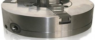
Scroll chuck
Self-centering spiral rack lathe chuck made of steel or cast iron, designed for installation on universal lathes, turrets, internal grinders, dividing heads and various devices.
3 x jaw chuck
3 x jaw lathe chuck
Lathe chucks are manufactured in 2 types:
TYPE 1 - with a cylindrical centering belt and fastening through an intermediate flange in accordance with GOST 3889-80; TYPE 2 - with fastening directly to the flanged ends of spindles under a rotary washer in accordance with GOST 12593-72.
Both types of cartridges are manufactured in the following versions:
version 1 - with solid jaws (odd) version 2 - with assembled jaws (even)
For two, four and six-jaw chucks, an index is added to the front designation - the number 2, 4 and 6, respectively. The three-jaw chuck does not have such an index.
Types of lathe chucks
Today, the following types of lathe chucks are in demand:
Belarusian:
Polish:
Chinese:
What does a lathe chuck consist of:
No. 1 - Key No. 2 - Spring No. 3 - Bushing No. 4 - Stopper No. 5 - Gear No. 6 - Flange No. 7 - Spiral disk No. 8.1 - Direct cam No. 8.2 - Reverse cam No. 9.1 - Rack (base cam - assembled) No. 9.2 — Direct overhead cam No. 9.3 — Reverse overhead cam No. 9.4 — Soft overhead cam No. 10. - Frame
Operating principle of a lathe chuck.
The housing 3 of this cartridge contains a steel bevel gear 4, on the reverse side of which there is a spiral groove. The cams 2 of the cartridge have several protrusions that fit into the spiral groove of gear 4.
When one of the three gears 1 rotates using a key (the square tail of which fits into the same hole in the end of the gear), gear 4 rotates.
Under the action of a spiral cut on the back side of this gear, the cams will move in the grooves of the cartridge body, which is what is required to secure the part.
Permissible runout of lathe chucks
The runout of a precision-machined part mounted in a new spiral chuck is 0.06–0.12 mm (depending on the chuck diameter). The magnitude of this runout quickly increases due to wear on the working surfaces of the gear spiral and the cam protrusions.
The centering accuracy of the chuck also depends on the condition of the grooves along which the cams move. When these grooves wear out, the cams move away from the chuck body when securing the part, and the position of the part turns out to be incorrect.
If the manufactured part goes beyond the tolerances, the best option is to replace the entire system of contacting pairs of the lathe chuck (provided that before this there were normal, permissible deviations):
- gear (No. 5)
- spiral disk (No. 7)
- cams (direct, reverse)
WATCH THE VIDEO:
Operation, design and maintenance of a three-jaw lathe chuck.
The cartridge is rolled up by means of a wooden rod inserted between its cams. Particular care must be taken when rolling the cartridge to the end to avoid injury to your hands. A wooden board must be placed under the rolled cartridge.
Types and purposes
Cams are divided into the following types:
- straight (parts are fixed from the outside);
- reverse (fastening from the inside of the part);
- overhead or “raw cams” (fixation of parts with a large diameter);
- prefabricated (racks, with hardened overhead cams).
Direct
Straight jaws are most often used to clamp parts. Each of them has two stages for fastening parts “for expansion” and one prism for “compression”.
The working platforms of the cam steps, into which the ends of the workpieces rest, serve to eliminate the end runout of the latter.
The following parts are attached using straight cams:
- small-sized (with the surface of the prisms - behind the outer side of the part);
- large-sized (usually hollow workpieces - the surface of the steps).
Reverse
In their design, reverse cams are the opposite of straight cams and are used for fastening “in compression” to the outer side of large-diameter parts.
The outer surface of the reverse cams can be used to install an additional fastening base that works to “unclamp” the inner surface of the workpiece.
Invoices
They are made directly by turners from steel or non-ferrous metals without additional heat treatment, and therefore are also called “raw cams”. They are attached to rails (supplied with the chuck), which are installed instead of direct or reverse cams.
Overhead jaws (“raw jaws”) are made in proportion to the shapes of the workpieces to ensure high centering accuracy.
Prefabricated
Prefabricated cams (universal, compound) consist of two parts:
- the bottom one is the same rack with combs (moves along a spiral disk);
- top – cover (with standard hardening of the working area).
The linings are cams - inversions (direct - reverse). They differ from overhead or “raw” cams in that they are subject to mandatory heat treatment.
To change the view, just unscrew two bolts on each “reversal”, turn it to the desired side and secure it to the rail with the same bolts.
The versatility of prefabricated jaws makes it possible to reduce the preparatory time for processing a part, if it is necessary to frequently change direct to reverse and vice versa.
This type of jaws causes an error due to the reinstallation of the “reversals” and for this reason they are used in lathe chucks with a diameter of 250 mm or more. The magnitude of the relative error here is not so significant, but the labor costs for reinstallation are reduced significantly.
Purpose.
The self-centering three-jaw lathe chuck belongs to the class of spiral-rack self-centering three-jaw chucks with a cylindrical belt and mounting on a lathe through an intermediate flange. Self-centering spiral rack lathe chucks are designed for installation on universal lathes, turrets, and internal grinding machines. They are used in conditions of single, small-scale and mass production. Three-jaw self-centering chucks hold round and hexagonal workpieces or round rods of large diameter. Unlike wedge-type lathe chucks, they do not require time for readjustment in the case when installation to a different clamping diameter is required.
Prices and manufacturers
Turning jaws supplied to the Russian markets are represented by two manufacturers:
- BelTAPAZ is a Belarusian enterprise of lathe chucks and spare parts for them.
- Bison-Bial is a Polish factory that produces lathe chucks and metal-cutting tools.
Prices at dealer centers vary from 2,600 rubles for jaws for an 80 mm chuck, 2,800 rubles for a 100 mm chuck, and from 18,400 rubles for a 400 mm lathe chuck. Always approximate and tend to grow significantly.
Over the years of creative work, a generalist machine operator has accumulated entire “deposits” of various fastening units and parts. This indicates a special attitude towards the variety and quality of these devices.
Attention is also paid to manufacturers; sometimes a unique fashion for a particular brand is very relevant.
It is very important that the market continues to be replenished with, albeit expensive, but competitive and quickly payback products for metalworkers
What shapes do needle files have?
Diamond needle files are available in 12 types.
- Tools with three edges. They have a sharp or blunt end. This indicator determines the area of use of the device.
- Devices made in the shape of a rhombus. They make it possible to play with notches at a certain angle.
- Wedge-shaped devices are used when working with castes and valves (jewelry elements), as well as with angles with small values. Wedge-shaped devices have both a sharp and a rounded edge, but the nose of the device is sharp.
- The flat diamond needle file has versatility of use. The area of use depends on the size of the device.
- Grooved devices are similar to flat ones, but the edges on the sides are rounded. This makes it possible to treat hard-to-reach areas.
- Square devices are designed to work with grooves of a similar shape.
- With a semicircular shape. With their help it is possible to work with reliefs.
- Needle files with different convexities process the inner part of the ring.
- Oval fixtures are designed for holes.
- The round diamond needle file is able to work with rounded products. In addition, with their help, the required relief is created.
- The needle shape is fundamentally different from all other types. Firstly, it should be noted that these devices are miniature. The length of the working surface is 35-55 mm. Secondly, their tail is square.
- Another special type is the needle file. It should be discussed separately.
Devices with a blunt nose have the same cross-sectional size along their entire length. In pointed models, the cross-section of the rod decreases towards the edge of the device.
The notching itself is also performed in accordance with the standards. The main working parts of the tool have a double notch: main and auxiliary. Tools with a round or oval shape can have a single or spiral single cut.
How to squish it correctly?
To properly bore the cartridge, you must follow the sequence of actions. Professional boring is carried out in several stages, each of which must be performed with high quality and in accordance with all technical requirements.
Dismantling
First of all, it is necessary to dismantle the cartridge. Otherwise, it will not be possible to get rid of the workpiece runout and accurately align all the necessary axes. If the chuck is not clamped, but is in a free state on the machine, the defects will remain. After dismantling, it is necessary to remove the cams and clean them. Then you need to check the runout.
Sandpaper treatment
If there is a slight degree of wear and scuffing, it is enough to treat the part first with coarse-grained and then fine-grained sandpaper. In order not to distort the cam profile when sanding, it is necessary that the sandpaper covers approximately half of the cam profile and at the same time have a slight tension. If the cam wear is significant, full boring is necessary.
How to sharpen?
To groove the cams, a certain order must be followed:
- Install them by aligning them with the hole in the lathe chuck.
- Clamp the ring so that it can move freely.
- You will need two cutters: one for boring grooves, and the second for developing planes.
- Starting from low speeds, you should find the optimal rotation mode.
- The cutter for disassembling the planes must be installed so that contact occurs along the entire plane of the fists.
This way, conical boring is carried out and the workpiece can be fastened securely and safely.
Grinding
This is the final stage of boring, which is carried out only if there is a real need. At the same stage, a test is carried out with a metal shaft. The shaft is fixed in the chuck of the lathe and with its help it is possible to determine whether there is any runout. If there is runout, additional grinding is required.
Turning the jaws of a lathe chuck - how to fix the jaws in a compressed state
Turning the jaws of a lathe chuck - how to fix the jaws in a compressed state
Post #1 AZM.SU » Mar 19, 2021, 03:08
There is a fierce, mad desire to sharpen straight cams, because they give an error of ten when clamping (one cam with a worn surface, from the previous owner of the machine). For now, I’m trying to get by by sharpening the important parts into one installation, but this is unpleasant and inconvenient.
Who simply fixes straight cams in a compressed state with what and how? I saw on YouTube that some people put a block on the back tooth and squeeze it, and then lower the back tooth. I saw a device where there is a ring, C-shaped plates are attached to it and they grip the cams using their taper.
Basic tips and tricks
Any experienced turner has several secrets of his own for the optimal process of boring the jaws of a lathe chuck. The following recommendations work most often:
- when the master makes a groove on the cams, he must move them apart by 2/3 of the maximum reach;
- the clamping washer should be installed as close as possible to the ends of the cams;
- When boring the cams, the ring that is clamped in the recess should be as rigid as possible.
These subtleties must be known in order for boring to be effective and achieve the desired result.
If the jaws of lathes are not bored, this will lead to runout of the chuck, and then to breakage of the main components
It is important to follow all stages of this operation and remember that the cartridge will have to be dismantled in any case
ความคิดเห็น • 140
Hello, in the first case with the ring, after pressing it does not shrink? Or is it quite thick?
blowing through the cartridge, all the abrasive gets inside the cartridge
why use a 16k20 cartridge for 160?))
This is not 16k20 but 16B16ka
YOU'RE FUCKED WITH YOUR HUNDREDS OF HOW TO SPEND AND WHAT TO SPEND
What's the point of checking runout on newly clamped parts if they are never clamped the same way? Each clamp can produce a different beat and, if you’re lucky, no beat at all. It has nothing to do with the machine or the cams. This is a useless operation that deceives you. Grind the part and then check it.
Yes, guys, haven’t you seen yet what a cartridge hits?
you're a slow person
I haven’t seen so many fists together!
in the faceplate, bearing, and carriage, the weave is gained when boring 3 weave
Synthetic coolant concentrate KS-11A @t
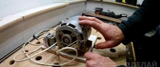
Kettle. Put El. Drive the motor into the tool holder to make the stone rotate.
As a Turner I will say: a good way of boring! Checked The main thing when boring is to maintain the limb for better clamping
Thank you . With feeling, with sense, with arrangement.
Whatever diameter you bore for, that will be zero!
Eprst, it just dawned on me, thanks to your phrase, that this is probably the end of my patron
Everything would be fine, but the cams in the chuck work to clamp the part, while in the case of the author, when the ring is clamped, the chuck begins to work to unclamp. Interesting..
So everything is correct, but I would not tighten the nut, there are other more precise materials, and a washer can be taken, for example, from a bearing race, I think better results can be achieved.
Overview of species
Different spray-coated tools can vary significantly in performance, despite the fact that they are all used for metal work. Some are needed for roughing, others for finishing sanding or filing small parts. According to GOST 1513-67, needle files must be marked indicating the main parameters. Tools can be divided into groups according to a number of characteristics.
By shape
The type of profile indicates for what purpose a particular file is suitable. Acceptable forms are established by the state standard. There are quite a lot of them, which allows you to choose tools for different stages of work.
Flat, with a blunt nose:
- have a rectangular shape;
- have 4 edges, 2 of which are wide and the rest are narrow;
- Suitable for both processing flat surfaces and cutting grooves and other hard-to-reach places.
There are also flat needle files with a sharp nose. They are distinguished by a different shape of the tip of the working part, otherwise they have the same features as obtuse-angled products.
Rhombic:
- upper corners – blunt;
- there are diamond-shaped edges;
- scope of application – processing of parts with different angles.
Square products are needed for filing rectangular grooves. All edges of the tool are working.
Triangular files come in two types:
- pointed - suitable for processing external grooves in small parts, all edges are involved in the work;
- obtuse-angled - they can have either one working side or all three; the latter option is more popular.
Round instruments usually have a sharp tip. They are suitable for turning relief elements. Similar in shape are oval models; they can be used to process round parts.
To size
Product parameters are usually indicated in the labeling. It can contain three numbers, for example, one of the popular sizes 140x70x3, where 140 mm is the length of the product, and 70x3 mm is its cross-section. Files with parameters 140x50x3 are also in demand. For some shapes, the section is indicated by one number, for example, a 4 mm round needle file.
The length of the products may vary, but the most commonly used tools are 80 mm, 120 mm, 160 mm. If necessary, you can purchase a file from 100 mm to 450 mm for work.
By grain level
Depending on the purpose, the coating of the file may vary
It is worth paying attention to the density of the grains. If there are few of them, then after processing the product will be rough, but with a fine-grained file you can make the surface smooth
For convenience, color markings are applied to the handle of the instruments:
- red – grain density ranges from 160 to 80 units;
- blue – grain size ranging from 80 to 55;
- if there are no markings, then the coating may have 50-28 grains per 1 cm2.
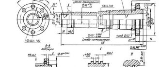
Machine design
All components of the machine, the diagram of which is shown in Figure 14, are mounted on the frame
made of gray cast iron
.
The bed is equipped with horizontal prismatic guides
.
The electric motor
is mounted in the front cabinet .
In the rear cabinet
there is a tank for storing
cutting fluid
and
a pumping station
for supplying it to the cutting zone.
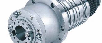
In the headstock
are located:
— spindle
– a hollow shaft on which devices for fastening the workpiece are placed (chucks, centers, faceplates, etc.)
— gearbox
, with the help of which stepwise
spindle speed adjustment. The gearbox control panel is located on the front panel of the headstock.
a feed box on the front side of the bed
, which allows for stepwise
adjustment by movement
of the longitudinal
and
transverse calipers
.
On the left end side of the frame there is a set of replaceable gears
, which are rearranged when setting up the machine for cutting different types of threads.
A longitudinal slide moves along the guides of the frame
, which provides longitudinal feed of the cutter
.
carriage is placed on the longitudinal support - a transverse support
, which ensures
the transverse feed of the cutter
.
The upper rotary caliper
is located on the transverse caliper .
With its help, the cutter can be installed at any angle to the workpiece axis
.
A four-position tool holder
is mounted on it , in which
four cutters
.
Figure 14 – Screw-cutting lathe 1K62
1 – front cabinet; 2 – bed; 3 – feed box; 4 – guitar of replaceable wheels; 5 – control panel; 6 – front headstock; 7 – longitudinal support; 8 – rotary support with tool holder; 9 – transverse support; 10 – apron; 11 – tailstock; 12 – bed
roller comes out of the feed box
and lead screw
, the latter is used when cutting precision threads.
The rotational movement of the lead shaft and lead screw in the apron
fixed to the longitudinal support is converted into
translational movement of the supports
.
Read also: Gas stove fire temperature
Tailstock
is located on the right side of the bed and moves along its guides. In the tailstock quill
a rear (movable
) center or hole-making tool
.
The tailstock
body move
transversely relative to its base, which is necessary when turning
external conical surfaces.
Dimensions
The common dimensions for direct and reverse cams are:
- the presence of identical sizes in terms of basic parameters - length, width, height, comb pitch, step sizes, etc.;
- are unified in their design, however, the set of jaws of one cartridge is not identical to the set of another (substantial modification is always required);
- cams with dimensional errors do not fasten the part correctly. At the same time, one of them does not participate in the clamping, forming a gap between the prism and the surface of the part, which is easily checked with a flashlight beam;
- wear on the surfaces of the disk spiral and the cams and racks significantly changes the characteristics of the clamping forces and the accuracy of the rotation part;
- inaccuracy in the linear dimensions of contact surfaces, for example, slats and pads, leads to displacement of the working surfaces, and hence, either excessive clamping forces or their absence at all, which is unacceptable and dangerous when working with such devices.
Jewelry Review
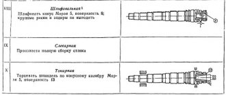
Sooner or later, depending on the intensity of work, a self-centering three-jaw chuck loses its accuracy due to wear of the rubbing parts (spiral, jaw guides in the chuck body, the jaws themselves). As a result of this, the chuck begins to “beat,” i.e., the axis of the cylindrical testing mandrel clamped into the chuck (or part) does not coincide with the axis of rotation of the lathe spindle. There is beating of the surface of the part when it rotates. This can affect the appearance of “blackness” when processing a workpiece with a minimum allowance for processing, and in other cases when it is necessary to maintain the alignment of the shaft journals when processing without the participation of machine centers.
The meaning of this operation is that it is necessary to align the axis of the working surfaces of the cams with the axis of rotation of the spindle. It would seem very simple to machine (bore) the chuck jaws directly on the machine along the working surfaces. This is true, but there is no point in boring the cams in a free state when they are not clamped - the runout will not be eliminated. The cams must be bored in their working position, that is, in the clamped position. There are several options for clamping the jaws so that the boring cutter can pass inside them. One of them is to use an insert ring on which the cams are loaded.
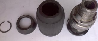
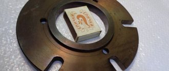
It is done this way: a cylinder is clamped into the chuck, the diameter of which determines the size of the hole into which the boring cutter will fit. On one of the steps of the cams a groove is cut for the bearing race. The depth of the groove corresponds to the width of the cage. The cylinder is removed, the bearing race is inserted into the grooves and clamped (not unclamped, but clamped). It is not scary if the ring is deformed when clamped; the main thing is that all the gaps in the cartridge joints are selected. In this position, the cams are bored. The boring radius of the cams should be as small as possible so as not to worsen the clamping conditions for small-diameter parts. Transverse grooves, which become less deep after boring the cams, can be cut without opening the cams after boring them. If the side edges of the jaws prevent them from coming together when clamping a small-diameter part, the jaws can be removed from the chuck body and milled with a milling cutter with carbide inserts.
Each cam must always be in its groove. The cam and groove must be marked accordingly and after cleaning the cartridge or repairing it, assembly must proceed according to the marks.
In general, this method can be used on all, not just universal, lathes, where self-centering chucks are installed and it is possible to install a boring cutter.
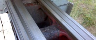
Disturbance in the centering of the cartridge may be due to micro-scratches on the ground working surfaces of the disk spiral and cam combs. They look like radial marks of varying depths, which are visible when inspecting cleaned parts.
It's easy to see the difference between a surface that was working properly and one that was damaged.
A very critical state of the working surfaces of the chuck is created by macro-scoring at any points of the spiral or cam combs, which leads to the occurrence of beats of parts clamped in the chuck of 0.2 mm or more.
This is what a local macro-seizure looks like, which appeared due to an attempt to unscrew the cams with great effort when the mating of the cam combs and the spiral was severely clogged with chips. We will now consider the reasons leading to damage to the spiral disk and cams - microclogging, lack of lubrication.
Despite the fact that all operating instructions for any cartridges indicate, in particular, that they need to be regularly washed, cleaned and lubricated, this operating requirement is beginning to be counteracted by an unknown, but very long-standing belief that it is not necessary and even impossible to lubricate cartridges.
All cartridges, rotating, work like centrifugal pumps, capturing air from the center and throwing it beyond their limits with the planes of the cams. Along with the air, aerosols and vapors of lubricating and cooling liquids, abbreviated as coolants, are captured. As a result, the disc spiral and cams appear lubricated, but in fact they are coated with a mixture of oils contained in the coolant, mixed with cutting waste products such as fine metal particles, scale, and abrasive from dry sanding, especially holes.
I think there is no need to explain what harm a mixture of abrasives and oil causes to any mechanism. If coolant is rarely used on the machine, the chuck mechanism will operate in dry friction mode, which inevitably causes micro and even macro scuffing on loaded rubbing surfaces, namely on the cam combs and the disk spiral.
A few words about industrial dirt. Any dark or black drop of oil contains many metallic, abrasive and other inclusions. If you place a drop of dirty oil on a micrometer, then by moving the measuring surfaces of the micrometer, you can see the size of the largest microparticles that make up the dark color of the oil.
It is clear that the presence of such oily dirt in the mechanism cartridge, instead of clean special lubricant, has not led and will not lead to anything good.
Reason 2: macro-pollution.
In addition to micropollution, there is also contamination from small metal shavings.
When boring through chalk holes, chips inevitably fall into unprotected gaps in the internal cavities of the chuck. Also getting into the interfaces of the cam combs with the spiral disk, chips can create very strong blockages between them and, as a result, jamming of these interfaces. Attempts to remove such severe blockages by forcefully unscrewing the cams, and even by lengthening the wrench lever with a pipe, lead to macro-seizing on precision surfaces.
RDA Group LLC
To order correctly, it is important to know the parameters S, F, C, B
| Reiki code | Ø Chuck diameter | A | IN | WITH | D | E | F | G | H | J | M | N | O | P | S |
| C 7100-0006.004 | 160 | 7,94 | 8 | 8 | 3 | 64 | 20 | 29,5 | 26 | 12,675 | M8 | 10 | 38 | 7 | 7 |
| С 7100-0032.009 | 200 | 7,94 | 10 | 8,5 | 3 | 77,5 | 28 | 32 | 35 | 12,675 | M10 | 16 | 44,44 | 7 | 8 |
| С 7100-0036.009 | 250 | 12,7 | 12 | 11,5 | 3 | 90 | 28 | 38 | 35,5 | 19,025 | M12 | 20 | 54,4 | 7 | 9 |
| С 7100-0036.009/01 | 250 | 12,7 | 12 | 11,5 | 3 | 90 | 28 | 38 | 35,5 | 19,025 | M12 | 20 | 54,4 | 7 | 10 |
| С 7100-0042.011 | 315 | 12,7 | 12 | 13 | 3 | 107 | 36 | 40 | 50 | 19,025 | M12 | 14 | 63,5 | 7 | 10 |
| С 7100-0046.008 | 400 | 12,7 | 12 | 15 | 3 | 127 | 36 | 49 | 54 | 19,025 | M16 | 20 | 76,2 | 12 | 10 |
We ourselves deliver jaws for lathe chucks to the terminal of transport companies in Moscow, which significantly reduces delivery times and reduces costs. We supply our products to all cities of Russia: Maykop, Gorno-Altaisk, Ufa, Ulan-Ude, Makhachkala, Magas, Nalchik, Elista, Cherkessk, Petrozavodsk, Syvtyvkar, Yoshkar-Ola, Saransk, Yakutsk, Vladikavkaz, Kazan, Kyzyl, Izhevsk , Abakan, Grozny, Cheboksary, Barnaul, Chita, Petropavlovsk-Kamchatsky, Krasnodar, Krasnoyarsk, Perm, Vladivostok, Stavropol, Khabarovsk, Blagoveshchensk, Arkhangelsk, Astrakhan, Belgorod, Bryansk, Vladimir, Volgograd, Vologda, Voronezh, Ivanovo, Irkutsk, Kaliningrad , Kaluga, Kemerovo, Kirov, Kostroma, Kurgan, Kursk, St. Petersburg, Lipetsk, Magadan, Krasnogorsk, Moscow, Murmansk, Nizhny Novgorod, Veliky Novgorod, Novosibirsk, Omsk, Orenburg, Orel, Penza, Pskov, Rostov-on-Don , Ryazan, Samara, Saratov, Yuzhno-Sakhalinsk, Yekaterinburg, Smolensk, Tambov, Tver, Tomsk, Tula, Tyumen, Ulyanovsk, Chelyabinsk, Yaroslavl, Birobidzhan, Naryan-Mar, Anadyr, Salekhard. And also to neighboring countries - Kazakhstan, Ukraine and Belarus.