Brief information about the manufacturer
In Samara, opposite the city park, there was a vacant lot where mechanic Gotthard Behnke began building a foundry in 1876. At first, the company produced iron and copper castings and repaired steamships and other equipment.
After being included in the metalworking workshops, the plant began to be called Mechanical. Three years later, the first screw-cutting lathe was produced.
In 1937, the specialization of the Saratov plant was finally determined. He completely switched to the production of machine tools. In 1948, automatic lines were launched and mass production was organized. Since 1951, the Saratov Machine Tool Plant began producing metal-cutting equipment for export.
The 16B16KP screw-cutting lathe began to be mass-produced in 1970. It was modified several times and models 16B16A, 16B16KA were created. Most of the equipment is still in working order.
Important!
Currently, SVSZ produces various models of CNC lathes and automatic lines under the Samat brand.
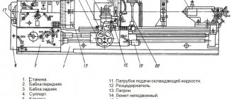
Components of the apparatus
The units of the electrical unit are:
- bed;
- caliper;
- apron;
- tailstock;
- gearboxes, feeds, speeds;
- electrical equipment;
- protective device.
The bed is the main element of the 16b16kp screw-cutting lathe. It consists of cast iron. It is characterized by a box-like structure. Inside the frame there are U-shaped ribs. Due to them, the structure is rigid.
The bed is equipped with four guides at the top. Two guides have a flat structure, the other two have a prismatic structure. All guides are hardened and ground.
The device is mounted on a cabinet. On the right side of the frame there is an electric motor, thanks to which the longitudinal slide moves quickly. The left rear part of the frame is equipped with a gearbox, and the right rear part is equipped with a lubrication device.
Inside the cabinet there is a main motor that drives the main movement. To the right of the cabinet is the lubrication system of the unit, which includes a pump and a container with cutting fluid.
The support facilitates the correct positioning of the cutting tool. He is also responsible for its transverse and longitudinal movements. The caliper moves due to a mechanical or manual drive. The longitudinal slides are secured with a special screw.
The machine apron includes 4 pairs of clamps. Thanks to them, the carriage of the device can move both forward and backward.
The tailstock is connected to the frame by means of a handle. Its position is controlled by a mandrel located in the centers of the apparatus, or by marks. The discrepancy between the spindle rotation axis and the rear quill must exceed 0.1 mm.
Gearboxes and unit feeds, protective mechanism and electric motors
Thanks to the gearbox of an electric screw-cutting machine, rotation of the feed box shaft is ensured. The unit is equipped with a protective casing with a locking system. It prevents the machine from turning on if the machine guard is missing or open.
The type of transmission gear set depends on the type of thread. For inch and metric, the main set is used, for pitch and modular - an additional set.
The feed box of a screw-cutting lathe is equipped with gear wheels. The rotation is transmitted to them by the gearbox shaft located in the spindle head. The knot handles allow you to:
- choose the type of thread;
- direct the rotation of the screw;
- set thread pitch and value;
- include a roller or drive shaft.
The feed box is able to connect the screw without the use of gears. The box is equipped with an overrunning clutch, which disables the mechanism during rapid reverse movements of the caliper.
The screw cutting machine 16b16kp is equipped with a protective mechanism against metal shavings, which meets safety requirements and increases the service life of the device.
The device has 4 asynchronous motors. The device operates at a network voltage of 220-440 V.
Purpose and scope of screw-cutting lathe
The 16B16KP precision lathe is designed for finishing – finishing machining of round parts:
- finishing of cylindrical and conical surfaces;
- pruning;
- end processing;
- cutting metric and inch threads with a cutter and die;
- turning pitch threads;
- drilling in the axle from the tailstock side;
- boring.
High precision pitch adjustment allows you to cut multi-start threads on screws. The tool is quickly removed from the working area without touching the adjacent surface, thanks to the quick retraction mechanism of the tool holder.
Important!
The machine model 16B16KP is available in a tropical version - work in conditions of high temperatures and humidity.
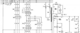
Scheme of the machine 16B16KP. Screw-cutting lathe. Electrical principle
Below is a sketch of the electrical circuit diagram of the 16B16KP lathe
You can download a free electrical diagram of the 16B16KP screw-cutting lathe in good quality from the link above. It is contained in the Electrical Manual
Design
Model 16B16KP was created on the basis of the previously produced lathe 1A616 and 16B16. Its positive characteristics are based on the design features of the lathe:
- Automatic transmission;
- smooth adjustment of cutting speed;
- high processing accuracy – precision;
- 2 busts are installed in the headstock;
- four-position tool holder with quick withdrawal mechanism;
- automatic selection of the optimal cutting mode due to the presence of an electric drive using thyristors.
Reference. The ergonomics of the machine – ease of use – have been significantly improved. The turner controlled all operations, making a minimum of movements.
Headstock:
On the right above the bed is the most complex component of the machine - the headstock. It contains nodes:
- gearbox;
- Transmission;
- spindle unit;
- splash lubrication system.
The oil simultaneously lubricates and cools the gears, washing away dirt and metal dust from them.
Important!
The bearings are filled with grease during each maintenance inspection.
Guitar:
The gears located at the ends of the shaft and screw are located inside the headstock housing and are covered with a cover. Driven by V-belt transmission. The set of gears depends on the type of thread being cut.
Reference. When the guitar cover is opened while the machine is running, a lock is activated.
Caliper:
The support moves along the machine along the bed guides. It has mechanical driving modes: working and accelerated idle. On the apron there are handles for mechanical movement and manual supply of tools.
The slide with the tool holder moves along guides in the longitudinal and transverse directions. The simultaneous activation of feeds in 2 perpendicular axes is blocked by a device on the control handle.
Tailstock:
Located on the right side of the bed. It is attached to the guides with clamping strips and screws. A quill is installed inside the body, in the same axis with the spindle. It is moved manually by a handwheel located at the rear and clamped using a handle.
Morse quill cone No. 2. It states:
- center;
- drill;
- countersink;
- tap for cutting internal threads.
The tailstock moves along the guides manually. Fixed in place by straps located underneath. They are brought into working condition by a lever.
During adjustment, the quill is adjusted coaxially with the spindle using adjusting screws. The permissible displacement is less than 0.01 mm.
Apron:
The machine's running shaft and screw pass through the apron. Cam clutches with bevel gears convert torque into forward motion: forward and reverse motion of the caliper and carriage.
On the apron there are handles for controlling the caliper, slide, and switching cutting modes. The amount of displacement of the tool relative to the part is calculated from the divisions of the dial and vernier with an accuracy of 0.1 mm.
The movement of the caliper and slide forward and backward is started using the joystick. Its unit is equipped with a device for blocking the simultaneous activation of the working stroke in different directions. When you press the button in its handle, high speed is activated.
On the sides of the apron, above the guide, limit switches are installed. Having reached the extreme point, they are triggered and stop the caliper.
Gearbox:
The precise pitch when cutting threads is ensured by the lead screw. Its rotation, associated with a certain ratio with the revolutions of the part, is ensured by the feed box. It is located at the rear and rises above the headstock.
Transmission:
The gearbox is located at the bottom of the headstock, under the spindle assembly. It transmits torque to the drive shaft of the feed box.
Gearbox:
The automatic transmission is located at the rear of the headstock. She rotates the spindle. The presence in it of two searches: 1:4 and 1:16 increases the choice of the number of revolutions of the workpiece.
Principle of operation:
When you press the "Start" button, the engine is turned on. Through cam clutches, torque is transmitted to the drive shaft of the gearbox. It drives the lead screw through the feed box.
The spindle is driven through an automatic gearbox that transmits rotation from the output shaft of the gearbox. The speed of its rotation is controlled by a knob on the headstock. She, in turn, switches the gears of the search.
Cam clutches installed in the apron transmit movement to the caliper. At the same time, the tool holder with the tool moves with it.
Description of the main components of the screw-cutting lathe 16B16KP
Machine bed
The bed is a cast iron box-shaped frame with transverse U-shaped ribs - it has two prismatic and two flat guides. The guides are subjected to heat treatment followed by grinding. The bed is installed on one stand. In the niche of the right end of the frame there is an electric motor for rapid movements of the carriage.
A gearbox is mounted on the rear wall at the left end of the cabinet, a lubrication station is located at the right end, and the main drive electric motor is located inside the cabinet.
In the niche of the right end of the cabinet there is a coolant reservoir and a cooling system pump.
Automatic gearbox of machine 16B16KP
Automatic gearbox AKP 109-6.3
9 steps is mounted in a separate housing and attached to the rear outer wall of the left end of the cabinet.
To tension the belt running from the box to the spindle, the box can be moved in a vertical plane using a screw.
The gearbox mechanism is driven by an electric motor through a toothed belt drive.
Lubrication of electromagnetic couplings, gears and gearbox bearings is carried out from the lubrication pump by watering through pipelines I, 43 with fittings 2, 44.
Speed shift mechanism on machine 16B16KP
Control of automatic transmission AKP 109-6.3
installed on the machines, is done using handle 15 located on the electrical cabinet panel.
A description of the operation and design of the automatic transmission is given in the transmission manual.
Technical characteristics of the Automatic gearbox AKP 109-6.3
- Rated load torque on the output shaft - 138 N.m
- Output shaft rotation speed limits - 400..2500 rpm
- Rated input shaft speed: 1600 rpm
- Number of direct passes - 9
- Number of return transfers - no
- Output shaft speed range coefficient - 1.26
- Drive motor power - 7.1 kW
- Acceleration time - 2.5 s
- Braking time 2.0 s
- Voltage of power supply circuits of electric couplings - 24 V
- Weight - 140 kg
Spindle head of screw-cutting lathe 16B16KP
Drawing of spindle head of lathe 16B16kp
The headstock mechanism receives movement from the gearbox through a toothed belt and a balanced take-up pulley 7 (Fig. 6) with seal 4.
Pulley 7 sits on the cone of the clutch-gear 5, rotating on two angular contact bearings 3 located in housing 6.
The axial play in the bearings is sampled using spring 4.
spindle 16e16kp receives 21 rotation speeds from 20 to 2000 rpm;
- 9 speeds directly 1:1 from the gearbox, take-up pulley through clutch-gear 5;
- 9 speeds with 1:4 overdrive through overdrive gears 5, 8, 16, 15;
- 9 speeds with 1:16 overdrive through gears 5, 8, 11, 10, 13, 14, 16, 15.
Thus, the spindle receives 27 speed steps (9 x 3 = 27), of which 6 values are repeated.
Turning on the selector groups, gear clutch 12 or turning off the spindle for dividing into passes when cutting threads is carried out by handle 9 (see Fig. 3) using translations through a system of levers controlled by the curves of the cams.
Reliable fixation of the axis of the handle 9 from rotation in the working position is carried out by a spring-loaded ball located in a glass on the rear wall of the spindle head housing.
Spindle 17 (see Fig. 6) of the machine rotates on two tapered roller bearings 18 and 21.
The radial clearance in the bearings is selected using springs 20.
The machine spindle, which has a flanged front end, made in accordance with GOST 12593-72, ensures quick change of the faceplate and its reliable fastening.
The headstock mechanism allows:
- cut threads with an increased pitch of 4 and 16 times;
- cut right-hand and left-hand threads;
- cut multi-start threads when working with cuts 1:4 and 1:16 with the number of starts 2, 3, 4, 5, 6, 10, 12, 15, 20, 30, and when working directly with the number of starts 2, 3, 4 , 6, 12.
Transmissions are carried out by gears 1, 2, 22, 23, 24 and the wheels listed above.
Spindle bearings for screw-cutting lathe 16B16kp
The spindle of the machine 16B16kp is mounted on 2 tapered roller bearings:
- 18. Front bearing No. 4-697716 double-row tapered roller bearing, accuracy class 4
- 21. Rear bearing No. 4-17814 single-row tapered roller bearing, accuracy class 4
Adjusting spindle bearings
The set of spindle bearings is adjusted by the manufacturer and does not require adjustment during operation.
In case of replacing a set of spindle bearings during repairs, tightening the front bearing 18 (see Fig. 6) with nut 19 must be done before the radial runout of the spindle axis begins to change, while the torque on nut 19 should not exceed 5 Nm (approximately).
When tightening the rear bearing 21, the torque on the nut 9 should not exceed 110 Nm (approximately).
Technical characteristics of bearing No. 697716
Bearing 697716 is a roller, angular contact, tapered (or this type is also called “with tapered rollers”), double row, wide series.
A distinctive feature is the presence of a bead on the outer ring. It is used to absorb radial and double-sided axial loads, while the latter should not exceed 40% of the unused permissible radial load. Installed in units where high rigidity and durability are required, as well as high rotational accuracy at the same time. In light of the latter, bearings are produced only with 2nd or 4th degrees of accuracy and with brass cages, according to specifications: 12-697716L (radial clearance group - 1) and 14-697716L. In Russia, this bearing is manufactured at the Volzhsky Bearing Plant - 15 GPP (products are now labeled VPZ), or more precisely, at a branch of the Samara Aviation Bearing Plant, which exists at 15 PZ. It is best to buy bearings from one of the EPK dealers, to which both factories currently belong. The price of a bearing manufactured according to the second accuracy class is just over 10,000 rubles; according to the fourth, it is several hundred rubles cheaper. If these bearings are offered to you at significantly lower prices, then this is a reason to be wary - most likely they will be illiquid, at best - out of storage, with an expired preservation period and without a factory warranty.
Dimensions and characteristics of bearing 697716
- Inner diameter (d): – 80 mm;
- Outer diameter (D): – 140/147 mm;
- Width (H): – 85 mm;
- Weight: – 5.11 kg;
- Roller dimensions: - 13.19/14x23.4 mm;
- Number of rollers: - 39 pcs;
- Dynamic load capacity: - 249 kN;
- Static load capacity: - 446 kN;
- Maximum rated speed: - 3800 rpm.
Bearing diagram 697716 for lathe 16B16kp
Photo of bearing 697716 of a screw-cutting lathe 16B16kp
Technical characteristics of bearing No. 17814
Bearing 17814 is a roller, angular contact, tapered (or this type is also called “with tapered rollers”), single row.
This type is produced in accordance with TU 37.006.133. The contact angle of tapered bearings ranges from 10 to 18°, which allows them to operate under conditions of high radial and axial loads. A characteristic feature of the 17000 series products is the presence of springs on the outer ring.
Bearings of this type are currently produced only at one enterprise in the country - JSC Aviation Bearings Plant, or rather in its branch at 15 gas processing plants in the city of Volzhsky (modification 2-17814 L, with a brass cage, 2nd degree of accuracy or 4 -17814 L, lower fourth). The product you buy will probably have the designation 15 GPZ or VPZ - essentially, a branch of ZAP, this is just a workshop at this plant, and previously bearings of this type were produced with this marking. Unlike most other roller bearings of the 17000 series, this type has a more or less significant degree of applicability, so there should be no problems with its purchase, however, you can buy it mainly not from official representatives of the EPK, but from companies involved in the purchase and resale of bearing products ( roughly speaking, illiquid assets). They usually have this bearing of satisfactory quality and the price is much lower than the official factory price.
Dimensions and characteristics of bearing 17814
- Inner diameter (d): – 70 mm;
- Outer diameter (D): – 120 mm;
- Width (H): – 65.44 mm;
- Weight: – 2.54 kg;
- Roller dimensions: - mm;
- Number of rollers: - pcs;
- Dynamic load capacity: - 109.2 kN;
- Static load capacity: - 162.6 kN;
- Maximum rated speed: - 4400 rpm.
Bearing diagram 17814 for lathe 16B16kp
Photo of bearing 17814 of a screw-cutting lathe 16B16kp
Support for screw-cutting lathe 16B16KP
Drawing of a lathe support 16B16kp
The tool holder, with the help of a support, can move along and across the bed from a mechanical drive at working feed and accelerated, as well as by hand.
The carriage and transverse slider of the caliper have travel restrictions in both directions. When the caliper is moved all the way, the apron disconnect mechanism is activated.
If necessary, the support carriage (Fig. 11) can be secured anywhere on the frame using screw 18 (see Fig. 3).
Tailstock of screw-cutting lathe 16B16KP
Drawing of the tailstock of a lathe 16B16kp
The tailstock is attached to the frame through a system of levers and an eccentric handle I (Fig. 12).
If necessary, the transverse displacement of the body is carried out by screws 10, 12 with the handle clamp I in the released position.
Control of the correct position of the tailstock body is carried out roughly by the places pressed during assembly and precisely by the mandrel clamped in the centers of the machine.
In this case, the discrepancy between the axis of rotation of the spindle and the axis of the quill hole in the horizontal plane should not exceed 0.01 mm.
The flat end of screw 4 slides in the fixing groove of eccentric 3. To unscrew screw 4 to dismantle eccentric 3, it is necessary to align the counterbore A with screw 4.
The quill 8 is clamped by handle 7.
ATTENTION! MAXIMUM quill STROKE – 120 mm. Screw 9 moves from handwheel 2.
Box of replacement gears of the machine (Guitar)
The box of interchangeable gears is shown in Fig. 7 and serves to transmit motion from the output shaft of the headstock to the drive shaft of the feed box.
To obtain feed and cut metric and inch threads, gear wheels of the main set are installed with a gear ratio of 40/73 73/64, and for cutting modular and pitch threads - with a gear ratio of 60/73 * 86/36
The gearbox guard is equipped with an electrical lock, which prevents accidental activation of the machine when the guard casing is open.
Gearbox
The feed box consists of gears 1-14, 16-23 and receives movement from the headstock output shaft through replaceable gearbox gears.
The required feeds and thread pitches were set by turning handles 3 and 36 (see Fig. 3) located on the front cover of the feed box.
Turning on the lead screw or lead shaft, selecting the type of thread is done with handle 2.
The direction of rotation of the lead screw is changed by turning handle 7, normal or increased thread pitch is set by handle 6.
To cut more precise threads in the feed box, handle 2 is provided in a position in which the lead screw is engaged directly, bypassing the feed box mechanism. In this case, the required pitch is selected by interchangeable gear wheels of a special set.
To carry out rapid movements of the caliper, an overrunning clutch 15 is mounted in the feed box (see Fig. 8), the purpose of which is to turn off the feed box during the rapid return stroke of the caliper.
The mechanism for switching gears of the feed box is assembled on one plate 26, which is attached to the feed box body. The gears are switched using a system of levers, rods and cams. Fixation of the working position of the gears is ensured by spring-loaded balls located in the shift handles.
When dismantling the switching mechanism, it is necessary to ensure the correct installation of gear wheels 24 and 2.5, which have risks that must coincide during installation, otherwise the order of engagement of the gear wheels of the feed box will be disrupted.
Apron
Drawing of the Apron of the screw-cutting lathe 16B16KP
Drawing of the Apron of the screw-cutting lathe 16B16KP
The apron has four pairs of cam clutches I (Fig. 9), 2, 3, 4, which allow forward and reverse strokes of the carriage and support. The movements of the carriage and the lower part of the support are controlled by handle 19. The direction in which the handle is turned on coincides with the direction of movement of the carriage and support.
The inclusion of rapid movements of the caliper in the indicated four directions is carried out by additionally pressing the IB button built into the handle 19.
At the same time, the high-speed electric motor is turned on, which, through a V-belt transmission, communicates movement to the running shaft.
The amount of movement of the apron using the flywheel is counted along the dial and vernier with a division value of I and 0.1 mm, respectively.
The apron has a blocking device that prevents the simultaneous activation of the longitudinal and transverse feeds of the support and the machine's uterine nut.
The apron has a built-in safety mechanism against machine overload, adjusted to the maximum apron release force (6000 ± 500) H.
When working along the stops, the apron disconnection force can be reduced to the required value by using nut 6 and loosening spring 7.
The safety mechanism works as follows.
When the carriage meets the stop or when the worm gear 14 is overloaded and, therefore, stops, the worm 13, continuing to rotate, turns out and through the cracker 12, pusher II, thrust bearing 10, compressing the spring 7, pushes the cup 9 to the right.
The latch 8, falling into the slot of the glass 9, prevents the worm from returning to its original position.
With further rotation of the worm, the coupling 15 shifts to the right under the influence of the spring 15, the fine-toothed part of the coupling 15 disengages with the coupling 17. The worm 13 begins to rotate.
To turn on the apron, you need to release the glass 9 by lifting the latch 8.
Spring 7 will turn on the disengaged gear couplings 15. 17 and the worm 13.
To cut a thread, you need to set handle 19 to the neutral position and use handle 20 to turn on the nut. In this case, the rack and pinion gear should be disengaged by pulling button 5 towards you.
The apron, bed guides and carriage are lubricated by a plunger pump built into the apron cover.
Chip protection device
The chip protection device consists of a support guard and a machine guard.
The support guard, which has a folding transparent screen, is mounted on the carriage and moves with it.
The height of the screen can be adjusted.
The purpose of the machine guard, which consists (mainly) of a shield suspended from the back of the support, is to protect the space surrounding the machine from flying chips.
Stop for limiting the longitudinal movement of the carriage
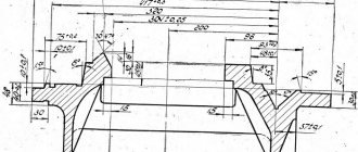
The stop for limiting the longitudinal movement of the carriage is installed on the front shelf of the frame, secured with screws and a clamping bar and equipped with a fine adjustment screw having a vernier with a division value of 0.05 mm.
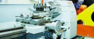
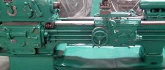
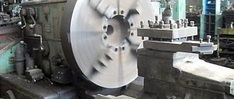
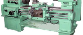
General form
The appearance of the 16B16KP model differs from most lathes by the automatic gearbox protruding above the tailstock and the ergonomic arrangement of levers and control buttons.
Kinematic diagram of a lathe model 16B16KP
Kinematic diagram of a lathe model 16B16kp
- A - AKS - automatic gearbox AKP 109-6.3 for machines 16B16K, 16B16KP, 16E16KP
- a - spindle head
- b - tool holder
- in — caliper
- g - tailstock
- d - apron
- e - carriage
- g - gearbox for machines 16B16, 16B16P, 16G16
* for spindle speed 16..1600 rpm
** for spindle speed 25..2500 rpm
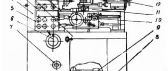
Location of controls
On the front surface of the automatic gearbox there are handles:
- rotation of the cutting head;
- caliper feed – transverse;
- automatic transmission control;
- turning on the coolant pump;
- start-up of electrical equipment.
A warning lamp and a load indicator are also installed there.
On the headstock there are plates with settings for cutting modes and interpretation of symbolic icons. There are also handles for setting and adjusting cutting modes, spindle speed and tool feed.
The movement of the carriage and the movement of the caliper are controlled from the apron. There is also a button to start the reversible spindle.
Electrical circuit diagram
Model 16B16KP has 3 electric motors:
- main, connected to the drive;
- responsible for moving the sled;
- driving coolant pumps.
The first two work in harmony. The locking system does not allow simultaneous activation of the transverse and longitudinal feed. The lubrication and cooling system is turned on simultaneously with the machine and operates independently of the main components.
Specifications
Screw-cutting lathe 16B16KP of precision type, high processing accuracy. Has an automatic gearbox.
Main parameters:
The machine model 16B16KP has 3 modifications, differing in bed length. Basic model parameters:
- maximum length of processed workpiece 750 mm;
- diameter above the bed 320 mm;
- above the caliper 180 mm;
- the cutter stroke from the axis of rotation of the part is 185 mm.
When working, cutters with a stem size of 25 mm are used.
Spindle:
Thanks to the presence of 2 busts, the speed of movement is adjustable from 20 to 2000 rpm, the number of steps is 24. The hole diameter is 46 mm.
The direction of rotation forward and backward has the same indicators.
Caliper and feed:
Mechanical and manual movement back and forth along and across the axis of rotation of the part.
Cutting slide:
They have a four-position tool holder. They move along perpendicular axes by mechanical feed and manually.
Tailstock:
The maximum distance from the chuck jaws is 750 mm. Morse quill cone2. Maximum stroke 120 mm. Adjustable relative to the axis of the part with an accuracy of 0.01 mm.
Electrical equipment:
2 electric motors operate synchronously, driving the main components. Power 5, 7.5 kW. The third includes the lubrication and cooling system pumps.
Dimensions and weight:
The weight of the model 16B16KP is 2270 kg with dimensions of 2525 × 1110 × 1505 mm (length, height, width).
Device characteristics
Currently, many modifications have been created, including the 16b16kp lathe. This model is one of the high-precision units. The device has an automatic transmission.
16b16kp has technical characteristics:
- unit weight - 1999 kg;
- Parts with a cross-section of 401 mm above the bed surface and 211 mm above the support surface are subject to processing;
- hole diameter in the headstock - 45 mm;
- the maximum permissible length of turning the workpiece is 146 cm;
- longitudinal feed direction - 0.1 cm;
- the maximum permissible length of the part used on the machine is 150 cm;
- transverse feed intervals - up to 1.4 mm/revolution;
- the rod fixed in the headstock has a cross-section of 4.4 cm;
- transverse feed direction - 0.025 mm;
- longitudinal feed intervals - up to 2.8 mm/revolution;
- speed of longitudinal movements of the caliper - 4 m/min;
- transverse movements of the caliper along the screw - 22 cm, longitudinal movements along the screw - 75 cm; along the roller - 50 cm;
- speed of transverse movements of the caliper - 2 m/min;
- spindle end category - 6K;
- rotation speed of the direct machine spindle - 25-2499 rpm, reverse - 25-1249 rpm;
- longitudinal feeds produced per 1 division of dial rotation - 0.1 mm.
Headstock design
The electrical system of the device is represented by electric motors with different power ratings:
- drive, due to which accelerated support movements occur - 0.36 kW;
- drive installed in the lubrication system - 0.11 kW;
- cooling system drive - 0.124 kW;
- main drive - 7.4 kW.
The screw-cutting lathe 16b16kp allows you to make 4 types of threads:
- modular - 0.5-21 mm;
- pitch - 0.5-111 mm;
- metric - 0.24-56 mm;
- inch - 0.5-111 mm.
Safety precautions at work
Limit switches and blocking devices installed in the machine mechanism protect the equipment from damage and the machine operator from injury. A transparent shield is installed on the support, covering the cutting area from flying chips.
Workers who have completed training and received qualifications are allowed to work on the machine. They must wear special clothing, a hat and glasses to protect their eyes.