The development of advanced methods for producing workpieces does not reduce the importance of proven mechanical metalworking. Metal cutting is being improved, while maintaining its main advantage - versatility in shaping parts. After all, the production of products of complex configuration is often possible only by milling, grinding, turning, etc. Metal-cutting machines have become automatic, which is important for such production of household appliances, cars, weapons, ammunition and others.
Standard size machines are in demand for experimental or service departments of such enterprises. They take up space in the production facility, consume a lot of electricity and require maintenance and repair costs. But at the same time, their capabilities are much wider than those of their more compact counterparts (desktop type).
It is more advisable to use such machines:
- For production, repair or tool areas.
- Small batches or individual production of parts.
- Pre- and finishing processing with normal accuracy class.
TIP: Make your final choice only after exhaustive consultation with several qualified specialists with recommendations and careful study of opinions on the Internet.
First of all, pay attention to proposals for the sale of warehouse storage machines, or, in extreme cases, overhauled ones.
Purpose and scope of screw-cutting lathe
This device is intended for a number of turning operations:
- cutting metric, pitch, inch and modular threads, as well as Archimedean spirals;
- processing of hardened bearings;
- turning of materials of different types, using shock loads that do not affect the accuracy of processing parts;
- making cuts using carbide tools.
1K625 belongs to the group of frontal lathes, which allows processing short workpieces with large diameters.
Design
The technological solutions used in the manufacture of this model of the machine in its design make it possible to perform a wide range of work with high precision.
Headstock
Located on the left side of the frame, it has the following fixed inside its upper part:
- spindle;
- gearbox
A jaw chuck, which is flanged to the protruding end of the spindle, is used to hold the workpiece before it begins to rotate. The electric motor is installed in the engine compartment, which is located in the lower part of the headstock.
Caliper
The speed of the caliper is set by the transmission setting range. The functions of the support include:
- implementation of transverse feed of the cutter;
- implementation of longitudinal feed of the cutter.
The caliper is driven by an apron mechanism, which is rotated by a shaft (to ensure turning operations) or a lead screw (to perform threading).
Tailstock
The design features of this unit allow processing of flat cones, which is achieved using its transverse displacement. By connecting this assembly and the lower part of the caliper (using a special clamp), you can drill and mechanically move it away from the caliper.
Gearbox
The feed box is fixed on the frame, which is located under the headstock. The box has shafts on which are located:
- Norton mechanism block, stepped (Fig. 12);
- gear blocks 6, 13;
- switchable clutches 1,2,4,5,7,14,15.
Clutch 7, moved to the right position, ensures rotation of the lead screw 9, and the drive shaft 10 begins to rotate when the overrunning clutch 11,12 is switched to the left position.
Apron
The housing directed towards the caliper carriage contains an apron mechanism (Fig. 14):
- worm wheel 3 rotates due to the influence (through a series of gears) of the drive shaft;
- The rotation of shaft I occurs with the help of a gear wheel of the corresponding shafts II and III; couplings with end teeth 2, 4, 10, 11 are located on them.
Clutches with end teeth ensure the process of turning on and moving the caliper in two planes, in four directions:
- for movement in the longitudinal plane it is necessary to use rack and pinion wheel 1;
- for movement in the transverse plane, it is necessary to use a screw that rotates under the influence of a gear wheel.
Handle 8 performs control functions for the lead screw 6 and the nut 7. The lead screw and shaft are locked using a shaft with cams 9.
Important!
This lock prevents the caliper from feeding when turned on at the same time.
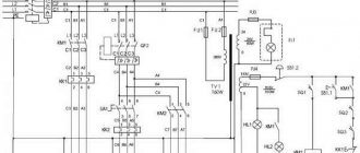
Electrical equipment
The purpose of the electrical equipment of the device is aimed at connecting to a three-phase alternating current network equipped with an insulated or solidly grounded neutral wire. Electrical components of the machine:
- control circuit - 50 Hz, 110 V;
- power circuit 3–50 Hz, 380 V, (220 V on special order);
- local lighting circuit - 50 Hz, 36/24 V.
Principle of operation
The operating principle of a lathe is as follows: after assembling, installing and connecting the machine, a workpiece or part is fixed in the designated units, after which the machine is started and work begins, for example, the required amount of material is removed with a cutter.
If necessary, you can use additional equipment (for example, for grinding or drilling), which significantly expands the range of tasks performed by the equipment.
Design features of the lathe 1k625
Turning flat cones on a 1k625 lathe is possible due to the features of its design.
Thus, the 1st method of processing conical surfaces requires a transverse displacement of the tailstock housing of the machine. As a result, the longitudinal axis of the workpiece forms an angle with the axis of the centers equal to the value of the taper. The cutter sharpens the forming surface of the cone. This option does not provide high manufacturing accuracy, because The position of the centering holes at the ends of the part is not correct relative to the centers of the headstocks.
The 2nd method is suitable for obtaining cones of small height. To do this, you need to rotate the caliper slide with the cutter to the required angle.
The most convenient way from the point of view of the accuracy of the cone and the absence of restrictions on its height is the use of a ruler-copier. It is fixed to the back of the frame on special brackets at the desired angle to the center axis. A slider moves along the copier with tight contact. It is rigidly connected to the machine support slide using a pin on the guide rod. As a result of the simultaneous combination of longitudinal (carrier) and transverse (slide) movement, the cutter creates a cone surface.
If in the above copying device you use a shaped ruler instead of a conical ruler, the cutting tool will completely repeat its curved shape. In addition, it is possible to use a copying support with a hydraulic drive. Then it becomes possible to turn stepped shafts on the machine.
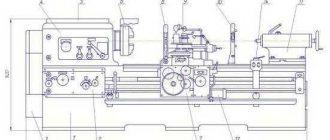
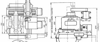
General form
Specifications
This section provides technical characteristics of the machine itself and its individual components and elements.
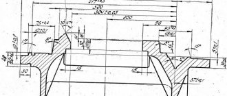
Main settings
It is allowed to use parts for processing if they do not exceed the following dimensions:
- 500 mm above the bed;
- 260 mm above the caliper;
- 45 mm in the spindle cavity.
In this case, it is permissible to use parts with a length of 1000, 1400, 2000 mm; the specific size depends on the modification of the equipment used.
The machine allows you to cut different types of threads:
- metric threads - 44;
- inch threads - 38;
- modular threads - 20;
- pitch threads - 37;
- Archimedes spiral - 5.
Spindle:
- Diameter of through hole in spindle, mm: 47.
- Largest rod diameter, mm: 45.
- Number of speed steps for direct spindle rotation: 24.
- Direct spindle rotation frequency, rpm: 12.5..2000.
- Number of spindle reverse rotation frequency steps: 12.
- Spindle reverse rotation frequency, rpm: 19..2420.
- Size of the internal cone in the spindle, M: Morse 6.
- Spindle end according to GOST 12593-72: 6K.
Caliper:
- Maximum stroke length of the carriage, mm: 930, 1330, 1920.
- Maximum lateral stroke of the caliper, mm: 300.
- Maximum stroke of the upper support (cutting slide), mm: 150.
- Number of longitudinal feed stages: 49.
- Limits of longitudinal working feeds, mm/rev: 0.07..4.16.
- Number of cross feed stages: 49.
- Transverse working feed limits, mm/rev: 0.035..2.08
- Speed of fast movements of the caliper, longitudinal, m/min: 3.4.
- Speed of fast movements of the caliper, transverse, m/min: 1.7.
- Number of metric threads cut: 44.
- Limits of metric thread pitches, mm: 1..192.
- Number of inch threads to be cut: 38.
- Limits of pitches of cut threads inch: 24..2.
- Number of modular threads to be cut: 20.
- Limits of pitches of cut modular threads: 0.5..48.
- Number of pitch threads to be cut: 37.
- Limits of steps of cut pitch threads: 96..1.
Electrical equipment:
| Type | Model | power, kWt | Node, purpose |
| Electric motor | AO2-52-4F | 10 | main drive |
| Electric motor | AOL2-12-4F | 0,8 | Fast travel |
| Electric motor | AOL2-22-6F | 1,1 | Hydro station |
| Electric motor | PA-22 (pump) | 0,125 | Cooling pump |
In total, the machine is equipped with four electric motors.
Dimensions and weight:
- machine weight (RMC = 1000), t: 2.4
- machine dimensions (length/width/height) (RMC = 1000), mm: 3212x1216x1349
Review of the 1V62G machine: description, technical characteristics, photos
The 1V62G universal turning and screw machine was produced by the Astrakhan Machine Tool Plant. Its design takes into account the shortcomings of similar models, as a result of which the equipment has wider functionality and improved performance parameters.
Machine Features
The main feature of the 1V62G screw-cutting lathe is the recess on the bed. It is closed with a removable bridge, by removing which you can process large-sized parts of various shapes (rings, disks, cylinders, etc.) with a diameter of up to 62 cm.
To ensure the most accurate processing, the 1V62G machine bed is made in the form of a rigid box-shaped form. At the same time, ground guides have fairly high mechanical strength. The machining accuracy is affected by the spindle design, which includes rolling bearings.
In addition to the main parameters of the 1V62G machine, the following design features can be highlighted:
- tool holder configuration. It is designed in such a way that it provides stable fixation of the cutter;
- apron. Has a unique mechanism for disabling the main caliper;
- increased protection measures. They consist of correctly selected blocking and fencing devices;
- universal clamp design. This makes it possible to attach various types of cartridges to the spindle assembly.
These characteristics make it possible to use 1V62G machines to complete small-scale production or workshops. It is also worth highlighting the relatively small dimensions of the structure (280*119*145 cm) and weight – 2430 kg.
To ensure operability, the machine is equipped with three three-phase asynchronous motors - 7.5, 0.75 and 0.12 kW.
Specifications
The review of parameters should begin by indicating the accuracy class of the machine. It corresponds to the “H” index according to the accepted classification according to GOST 8-82E. Conventionally, technical characteristics can be divided into several groups - basic, spindle and feed.
The maximum permissible diameter of the part above the machine bed is 44.5 cm. The same value when the workpiece is located above the support should not exceed 22 cm. The parameters are indicated with a closed recess. The dimensions of the part cannot be more than 75, 100 or 150 cm. The turning length limits are 65, 90 and 140, respectively.
Spindle parameters
The main parameters of the spindle head are the number of speeds (21) and the frequency of direct shaft rotation (from 10 to 1400 rpm). For reverse rotation, the number of feet is halved to 12.
In addition, the following characteristics of the 1V62G machine spindle should be taken into account:
- internal cone size – Morse 5;
- the end of the spindle according to the accepted classification according to GOST 12593-72 - 6K.
Thanks to the presence of rolling bearings in the design, timely adjustment of the spindle can be performed. Special nuts are provided for this. They correspond to metric size M6.
Regulation
Adjusting device components is a natural workflow that the machine operator must periodically resort to during work. In order to avoid mistakes in this process, it is advisable to have the technical data sheet of the device at hand or ask for advice from more experienced colleagues.
Main drive belt tension
The spindle torque may decrease over time during operation of the machine, which means it is necessary to check the tension of the V-belt drive belts, which goes from the main motor to the friction shaft of the device.
To perform this procedure, you must:
- Remove the lower casing.
- Loosen the wedge pin nut that secures the under-engine plate.
- Lower the stove until the belts have the required tension.
- After finishing work, tighten the nut.
Adjusting the friction multi-plate clutch
If it is necessary to increase the spindle torque with normal belt tension, it is possible to adjust the friction clutch of the main drive. For this:
- The main drive motor turns off.
- The top cover on the headstock is removed.
- The oil distribution tray is removed.
- By turning round nut 2 (Fig. 12), the forward rotation clutch is adjusted; turning nut 3 adjusts the spindle reverse rotation clutch. The nuts can be turned only after the latch 4 is inserted into the ring 5 (Fig. 12).
- Handle 20 (Fig. 5) is moved to the lower position to adjust the forward rotation clutch, to the upper position for reverse rotation; before performing these procedures, it must be moved to the extreme left position (16:1 selection is turned on).
To adjust, it is usually enough to perform 1/12 of a turn, focusing on the grooves that are located along the periphery of the nut (there are 12 of them), and it is necessary to control the movement of the latch into the groove, otherwise the nut may spontaneously unscrew during operation.
If you tighten the clutch fasteners too much, then turning on the handle 20 (Fig. 5) will be difficult. In this case, it is necessary to loosen the nuts.
Adjusting the band brake
The level of tape tension affects the total spindle braking time; the norm is 1.5 seconds when braking the spindle without a fixed workpiece and chuck at 2000 rpm.
If the level of spindle braking is significantly lower than required, it is necessary to adjust the brake by tensioning the brake band 1 (Fig. 13) using nuts 2.
Lever 3 should be located symmetrically to the protrusion of the roller - rack 4 in the locked position of the spindle. Fixation of the roller in a certain position is ensured by a ball 5 with an adjusting spring 6.
Adjusting the spindle bearings
The double row front roller bearing and rear radial thrust bearings are factory preset and do not require further adjustment.
Eliminating the backlash of the caliper transverse movement screw
The backlash level should not be higher than 2 divisions on the dial, while screw 5 should be adjusted in such a way that it can be turned without difficulty by hand.
To sample the backlash:
- lowering screw 1 (Fig. 14) of the left part of nut 2;
- tightening the wedge that is between the nut halves (cut);
- wedge 3 is tightened by screw 4;
- the axial clearance in the screw pair is selected.
Installing the tailstock along the center line
When installing the tailstock strictly along the center line with the center axis of the headstock, it is necessary to align the plane of the plates (Fig. 15), using the corresponding screws No. 1 and No. 2 (Fig. 9).
How to adjust the steady rest lock
Adjustment of the lock of the fixed rest is carried out if the lock of its upper folding part is weakened, which leads to a lack of reliability of fastening of this unit. The procedure itself is carried out according to the instructions noted in the machine passport.
Machine passport 1A62. Lathe-screw-cutting
This operating manual “Universal turning machine 1A62” contains information necessary both for the maintenance personnel of this machine and for the employee directly involved in working on this machine. This manual is an electronic version in PDF format of the original paper version. This documentation contains the Passport and Manual (instructions) for the operation of the 1A62 universal lathe.
CONTENT
Introduction Purpose of the machine Machine characteristics Kinematic diagram of the machine Machine design
- Stanin
- Headstock (gearbox)
- Tailstock
- Guitar
- Feed box (reversible)
- Apron
- Caliper
- Lunettes
Cooling of working tools Electrical equipment and control of electric motors
- Main drive motor
- Electric motor characteristics
- Electric pump
- Characteristics of the pump motor
- Electrical equipment
- Wiring
- Electrical circuit operation
Machine controls Lubrication of the machine Transportation, installation and test run of the machine Setting up the machine Setting up the feed chain Maintenance and adjustment of the machine Maintenance of the electrical equipment of the machine Specification of ball and roller bearings Specification of accessories for the machine 1A62 Spare parts of the machine Replacement gears for cutting particularly precise threads Instructions for adjusting the front bearing spindle of a screw-cutting lathe, model 1A62 Machine passport Download the first version of the machine passport 1A62. Screw-cutting lathe (95 pages) in good quality can be found at the link below:
Safety precautions at work
Safety standards when using this machine do not differ from generally accepted ones:
- The worker must wear clothes that do not restrict movement, but not too loose, and use safety glasses.
- Use a wooden pallet to protect against electric shock during operation.
- Use the machine's protective cover when working.
Repair features
Most often, situations arise when a simple inspection and maintenance of the machine is not enough and it must be taken out of the production cycle and transferred for repair. The reason for repair may be wear of the guides on the frame, on the caliper, bearings, breakage of forks intended for shifting gears, loss of accuracy when processing parts. In addition, a loss of alignment between the spindle and the tailstock may be a reason for carrying out repair work.
The reason for taking the machine out for repair may be the results of tests for axial and radial runout. These tests must be carried out in strict accordance with the requirements of the operating instructions.
To diagnose rolling bearings, a test piece is processed and the results are compared with the requirements. Often, such checks and implementation of the necessary preventive measures help postpone major repairs.
Features of modification 1K625D
The main feature of the modification with the “D” index is the increased processing diameter, up to 1000 and 1500 mm, depending on the selected version of the machine with this index. The maximum processing diameter of the previous modification was 500 mm.
In addition, in the modification with the letter “D” the speed mode of accelerated movement performed by the caliper was exactly doubled; now this parameter corresponds to 4.5 m/minute. The variations of metric and pitch threads have changed significantly, but the number of options for inch threads has decreased.
The main drive received increased power to 11 kW and the weight of the machine increased significantly - up to 3100 kg.
Upgrade options
Usually, the possibility of modernization means the installation of a CNC, but the price of such improvements can reach the price of the device itself. In the case of the 1K625 model, the following components can be modified:
increased power with a more powerful electric motor; adding working gears. In addition, it is possible to mechanize the processes associated with the placement of workpieces, their removal and fastening.
Before installing new components, it is necessary to carefully calculate the feasibility of improving the machine, both from an economic point of view and from the point of view of its performance and resource.
But even without this, the 1K625 model has an excellent combination of reliability and ease of maintenance at the same time as the ability to perform work within the capabilities of the machine while achieving high quality.