Check 1. Straightness of the longitudinal movement of the caliper in the vertical plane
Test method
A. A level is installed on the support (closer to the tool holder) parallel to the direction of its movement.
The caliper moves longitudinally over the entire stroke length. Measurements are made no more than every 500 mm on machines with a slide stroke length of up to 6000 mm and no more than every 1000 mm on machines with a longer slide stroke length.
B. For machines with a slide stroke length of more than 6000 mm, testing can be done using communicating vessels, one of which is mounted on the slide, the other next to the machine.
Permissible deviations:
a) 0.02 mm per 1000 mm of caliper stroke length;
b) Over the entire length of the caliper stroke:
- 0.04 mm - for stroke lengths up to 2000 mm
- 0.06 mm - for stroke lengths up to 4000 mm
- 0.08 mm - for stroke lengths up to 8000 mm
- 0.10 mm - for stroke length up to 12000 mm
- 0.12 mm - for stroke lengths up to 16000 mm
- 0.16 mm - for stroke lengths up to 20,000 mm
Only convexity of the machine guides is allowed.
Check 2. Distortions of the caliper during its longitudinal movement
Test method
A level is placed on the support (closer to the tool holder) perpendicular to the direction of its movement.
The caliper moves longitudinally over the entire stroke length.
Measurements are made no more than every 500 mm on machines with a slide stroke length of up to 6000 mm and no more than every 1000 mm on machines with a longer slide stroke length.
When checking, the tool holder is shifted towards the center axis of the machine.
Permissible deviations:
a) For 1000 mm of caliper stroke length:
- 0.02/1000 for machines with the largest processing diameter up to 800 mm
- 0.03/1000 for machines with the largest processing diameter St. 800 mm
b) Over the entire length of the caliper stroke:
for machines with the largest processing diameter up to 800 mm
- 0.03/1000 - for stroke length up to 2,000 mm
- 0.04/1000 - for stroke length up to 4000 mm
- 0.06/1000 - for stroke length up to 8000 mm
- 0.08/1000 - for stroke length up to 12000 mm
- 0.10/1000 - for stroke length up to 20000 mm
for machines with the largest processing diameter up to 1600 mm:
- 0.04/1000 - for stroke length up to 2000 mm
- 0.05/1000 - for stroke length up to 4000 mm
- 0.08/1000 - for stroke length up to 8000 mm
- 0.10/1000 - for stroke length up to 20000 mm
for machines with the largest processing diameter over 1600 mm:
- 0.10/1000 - for stroke length up to 16000 mm
- 0.12/1000 - for stroke length up to 20000 mm
Check 3. Straightness of the longitudinal movement of the caliper in the horizontal plane
Test method
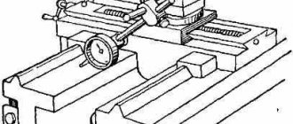
A. For caliper stroke lengths up to 3000 mm, the check is carried out using a cylindrical mandrel fixed between the centers of the headstock and tailstock, and an indicator.
An indicator is installed on the support so that its measuring rod touches the side generatrix of the mandrel. The indicator readings at the ends of the mandrel should be the same (this is achieved by appropriately installing the tailstock).
B. When the caliper stroke length is over 3000 mm, the check is carried out using a microscope mounted on the caliper and a string stretched along the frame guides.
The axis of the microscope lens is located vertically. The intersection of the threads of the ocular plate is combined with the side generatrix of the string at the beginning and end of the caliper stroke.
After achieving the specified conditions, the caliper moves in the longitudinal direction over the entire stroke length.
When checking, the tool holder is shifted towards the center axis of the machine.
The error is determined by the ordinate of the deviation of the trajectory from the original straight line.
Permissible deviations:
a) 0.02 mm per 1000 mm of caliper stroke length;
b) over the entire length of the caliper stroke:
- 0.03 mm - for stroke length up to 2000 mm
- 0.04 mm - for stroke lengths up to 4000 mm
- 0.05 mm - for stroke lengths up to 8000 mm
- 0.06 mm - for stroke length up to 12000 mm
- 0.08 mm - for stroke lengths up to 16000 mm
- 0.10 mm - for stroke lengths up to 20,000 mm
When moving, the support can only have a deviation towards the axis of the machine centers
Characteristics of processing accuracy
Let's understand the basic terms that characterize the concept. The first of these is the nominal size. This is the length, width, height parameter specified in the initial documentation. On the diagram according to which production takes place. It is usually stated with exceptions, but they are not considered part of it. So, with values of 35-05mm, only the first will be the nominal size. Accordingly, 25 millimeters.
But the actual size is the one obtained after the production process. It is detected by measuring the resulting hardware. And to clarify the need for further refinement, you need to turn to one more concept - the maximum size. It is already indicated as a nominal value with deviation. In our example, it is 34.5 mm. On the larger side, 35.5 mm. The range between these parameters is considered a tolerance.
But acceptable changes can also be top and bottom. The difference between the limit and nominal sizes is determined upward or downward, based on the limit vector. So, at 35-05mm we have 35 – 34.5 = 0.5, which turns out to be a positive sign, the upper limit. And at 35+0.5 mm, it turns out 35 – 35.5 = – 0.5, the lower one is observed.
Check 4. Parallelism of the tailstock guides to the direction of longitudinal movement of the caliper
Test method
An indicator is installed on the caliper so that its measuring rod touches the tailstock guide.
The check is carried out one by one for each tailstock guide - when using one indicator, or for all guides simultaneously - when using a set of indicators.
Measurements are taken in planes perpendicular to the corresponding tailstock guides.
The caliper moves longitudinally along the entire length of the tailstock guides.
Permissible deviations:
1. For vertical guides:
a) 0.03 mm per 1000 mm of caliper stroke length;
b) over the entire length of the caliper stroke.
- 0.04 mm - for stroke lengths up to 2000 mm
- 0.05 mm - for stroke lengths up to 4000 mm
- 0.06 mm - for stroke lengths up to 8000 mm
- 0.07 mm - for stroke length up to 12000 mm
- 0.08 mm - for stroke lengths up to 16000 mm
- 0.10 mm - for stroke lengths up to 20,000 mm
2. For horizontal and inclined guides:
a) 0.02 mm per 1000 mm of caliper stroke length;
b) over the entire length of the caliper stroke:
- 0.025 mm - for stroke lengths up to 2000 mm
- 0.03 mm - for stroke length up to 4000 mm
- 0.04 mm - for stroke lengths up to 8000 mm
- 0.05 mm - for stroke length up to 12000 mm
- 0.06 mm - for stroke length up to 16000 mm
- 0.07 mm - for stroke lengths up to 20,000 mm
Checking a lathe by a non-turner.
- 24 publications
- 1
- City: Khabarovsk region
- Members
(changed) Good afternoon everyone.
Happy past to everyone. I couldn’t find such information, although I searched almost the entire forum, so I’m asking for help from those who know. You can often see in advertisements for the sale of machines -
“Good condition, connected, can be checked in operation”
. So the question itself is this: what should I, as a complete zero in turning, see?
It seems like a lot has already been written and shown regarding checking an unconnected machine.
We recommend reading: Signature mismatch on documents law
Where to look and what to measure with what then depends on the tool that is available, but I couldn’t find anything in the control groove, maybe of course I was looking in the wrong place, so please don’t hit me. I would like to hear from those who know information in approximately this format: 1.
A groove without pressing the tailstock to a length of such and such, a range in size is acceptable 0.01-0.03 - good, 0.04-0.07 - will do, 0.1-0.2 is bad (you shouldn’t take it if you don’t want to get repaired right away, etc. 2 A groove with pressing to a length of such and such - such and such a run such and such is good, such and such is normal, such and such is repair.
3. The thickness of the bar is taken to be such and such, should it be sharpened using automatic feed or not, at what speed? 4. When facing a bar, what should you pay attention to? If anyone else can suggest something, it will only be a joy.
I wouldn’t want to hear questions like “read the passport data or machine repair instructions,” and I also wouldn’t want questions like “what accuracy is needed?” For the bulk of those people who ask questions here - (I don’t understand machines or I only saw a machine at a neighbor’s, etc.)
How to check the frame of the “porridge” for wear?
- Members
- 20
- 341 publications
Let's put together all the folk competent methods for beginners.
)) Well, firstly, in order to put one edge of the ruler on the right side of the guides, and the other edge on the left side, you need to disassemble and remove the caliper.
This means that this method will not work when checking a machine upon purchase.
So, as an option, you need to move the caliper to the maximum extreme right position, put a ruler on the guide under the cartridge and the other edge as close as possible to the caliper? And if possible, insert probes along the entire length of the plane being tested? Am I thinking correctly? How to properly check the rear flat guides?
If you measure the thickness with a micrometer along the entire length with a certain step, this method will give a complete picture of the production?
How can I test the bed for wear using a conventional indicator and an indicator stand?
Poke the indicator probe into the inclined surfaces of the guide prisms, and place the stand itself on the caliper?
Check 5. Radial runout of the centering journal of the headstock spindle
Test method
An indicator is installed on the machine so that its measuring rod touches the centering journal of the spindle and is perpendicular to the generatrix.
The spindle is rotated.
Permissible deviations:
- 0.010 mm - for machines with the largest processing diameter up to 400 mm
- 0.015 mm - for machines with the largest processing diameter up to 800 mm
- 0.020 mm - for machines with the largest processing diameter up to 1600 mm
- 0.030 mm - for machines with the largest processing diameter up to 3200 mm
- 0.040 mm - for machines with the largest processing diameter up to 6300 mm
Note This check does not apply to lathes with fixed faceplates.
Classification of lathes by degree of automation
The degree of automation is the ratio of the time of automatic transitions to the total processing time of the product on the machine.
The capabilities and classification of modern lathes by degree of automation are given in table. 1.12.3.
1.12.3. Classification of lathes by degree of automation
- Manual control
- Installation of workpiece and tool, positioning of working parts and formation of basic cycles manually. Automated positioning of working bodies and formation of basic cycles
- Semi-automatic control
- Consistency of manually generated basic cycles. Partial manual modification of basic cycle stages. Free modification of basic cycles with manual tool replacement
- Arbitrary automatic change of basic cycles with tool replacement. Arbitrary automatic change in the order of execution of basic cycles with a corresponding change in the order of operation of the tool. The same, including manipulations with the workpiece and the processed part. Fully automatic organization of the part manufacturing cycle
Check 6. Radial runout of the headstock spindle hole axis
Test method
A cylindrical mandrel is tightly inserted into the hole in the headstock spindle.
An indicator is installed on the machine so that its measuring rod touches the surface of the mandrel.
The spindle is rotated.
Measurements are taken at the end of the spindle and at a distance of l=300 mm from it.
Permissible deviations:
a) When measuring at the end of the spindle:
- 0.010 mm - for machines with the largest processing diameter up to 400 mm
- 0.015 mm - for machines with the largest processing diameter up to 800 mm
- 0.020 mm - for machines with the largest processing diameter up to 1600 mm
- 0.030 mm - for machines with the largest processing diameter up to 3200 mm
- 0.040 mm - for machines with the largest processing diameter up to 6300 mm
b) When measuring at a distance l=300 mm from the end of the spindle:
- 0.020 mm - for machines with the largest processing diameter up to 400 mm
- 0.025 mm - for machines with the largest processing diameter up to 800 mm
- 0.030 mm - for machines with the largest processing diameter up to 1600 mm
- 0.050 mm - for machines with the largest processing diameter up to 3200 mm
- 0.060 mm - for machines with the largest processing diameter up to 6300 mm
Checking the lathe and workpieces for accuracy
interferometer Rulers are used to check the straightness and flatness of surfaces.
Mandrels are used to determine the runout of rotating elements such as a spindle. The spindle bore is checked with a mandrel inserted into the spindle. The mandrel is rotated several times in half a circle, the runout is the difference between the maximum and minimum values. Perpendicularity is checked using a square.
An auxiliary tool is a feeler gauge, which is used to determine the presence and size of the gap between the plane and the square. It is also possible to use an indicator with a magnetic stand. The levels are intended to check the accuracy of equipment installation on the foundation in two planes. Accurate measurements are made by verified levels with a micrometric scale.
Machine tools can also be checked with special-purpose instruments - theodolites, profilometers and profilographs, interferometers.
Check 7. Axial runout of the headstock spindle
Test method
A short mandrel is inserted into the hole in the headstock spindle, the end surface of which is perpendicular to its axis.
The indicator is installed on the machine so that its measuring rod touches the end of the mandrel at its center or the surface of the ball inserted into the center hole of the mandrel (in this case, the measuring rod of the indicator is flat).
The spindle is rotated.
The check is carried out with the thrust bearings tightened.
Permissible deviations:
Permissible deviations:
- 0.010 mm - for machines with the largest processing diameter up to 400 mm
- 0.015 mm - for machines with the largest processing diameter up to 800 mm
- 0.020 mm - for machines with the largest processing diameter up to 1600 mm
- 0.030 mm - for machines with the largest processing diameter up to 3200 mm
- 0.040 mm - for machines with the largest processing diameter up to 6300 mm
Checking the machine transmission
To ensure high quality turning, it is necessary to constantly monitor the spindle speed. Not only the performance of the equipment, but also the cleanliness of the surface of the part depends on this parameter. Therefore, when repairing lathes, special attention is paid to the gearbox. The most obvious signs of a malfunction of this unit are extraneous noise (humming or ringing). They most often occur due to bearing wear.
SEE ALSO
Check 8. Axial runout of the headstock spindle support collar
Test method
An indicator is installed on the machine so that its measuring rod touches the end surface of the headstock spindle collar at the greatest possible distance from the center.
The spindle is rotated.
Measurements are made at at least two diametrically opposite points of the same diameter (the indicator is rearranged).
The error is defined as the largest value of the indicator readings.
The check is carried out with the thrust bearings tightened.
Permissible deviations:
Permissible deviations:
- 0.020 mm - for machines with the largest processing diameter up to 400 mm
- 0.025 mm - for machines with the largest processing diameter up to 800 mm
- 0.030 mm - for machines with the largest processing diameter up to 1600 mm
- 0.040 mm - for machines with the largest processing diameter up to 3200 mm
- 0.050 mm - for machines with the largest processing diameter up to 6300 mm
Note. The check does not apply to lathes with fixed faceplates.
Checking the machine before purchasing
Are you planning to buy a second-hand machine, but have doubts about the integrity of the seller? After studying this article, all your doubts should be dispelled, and you will gain complete clarity on the issue of purchasing the necessary equipment and will be able to check the machine yourself. Even if you are going to choose a drilling machine, read the contents of the article.
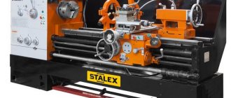
Figure 1. Typical appearance of equipment for sale
Visual inspection
Visual inspection is the first and cheapest inspection option. It is necessary to begin a visual inspection at the stage of viewing photographs of the equipment. You should not focus on equipment that is well painted and washed. Sometimes some craftsmen simply paint machines for appearance in order to sell them at a higher price. It is very useful to ask the seller to take photographs from other angles, since the seller in the ad posts the most successful photographs with a minimum of visible defects. Try to identify completely hopeless options even at the stage of viewing ads, this will save you time.
You will see serious defects immediately. Good equipment will not have large scratches or gouges on the guides, table, or covers. Large defects signal the low qualifications of former operators, and as a result increase the likelihood of future breakdowns and unscheduled repairs. If possible, inspect all accessible places of the machine, check all the screws securing the covers and casings. Their shortage or variety indicates that the machine was repaired by unqualified personnel and in a hurry.
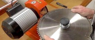
When the machine operates for a long time, deep abrasions from chips remain on the bed (near the spindle), which will be difficult to hide even with new paint. When checking a lathe, you don’t have to pay much attention to the condition of the installed chuck – it can be changed.
Check the condition of the scrapers on the carriages. If they are heavily worn, then the wear on the guides will be significant.
Figure 2. Example of poor condition of guides
Inspect the supports on which the equipment stands. If these are not adjustable supports, or one of the supports hangs freely in the air, then the machine was not leveled, which leads to increased wear on the guides and deformation of the bed (twisting of the entire bed).
Check the controls; their absence or breakdown indicates inattention to the machine. Especially on CNC machines. Some buttons may be integrated into the CNC rack, and replacing them will not be cheap. If the calibration on the machine’s gearboxes does not match, it means they have already been rebuilt, and possibly more than once.
Pay attention to the deterioration of the lead screws - sometimes they are worn out so much that it is visible to the naked eye.
Geometry and Mechanics Check
Ideally, checking machines for accuracy should be carried out according to the methodology set out in the relevant GOST. But for this you must have a fairly serious arsenal of testing tools: rolling pins, a corner, a frame, a micron indicator with a stand, a bar level. And there is not always enough time for such checks. You can find the full GOST check list here:
If you want to buy used machines, then you should carry out at least two basic checks that will put your mind at ease. To do this, you will need a magnetic stand and an hour indicator with a scale division of 0.001mm. It will cost no more than 6,000 rubles (2020).
- Checking the machine for axis play - move the machine along any axis in the positive direction until visible movement appears. Having stopped the movement, we take this value as zero and slowly move the axis in the other direction. The idle length of the axis will be the value of the backlash of the machine axis. For universal machines, the presence of uniform backlash is normal practice (around 0.2 mm). But on CNC there should be practically no backlash (in the region of several microns). But there is a trick that the CNC rack automatically compensates for the backlash, and you can only see the backlash compensation parameter in the rack parameters. If it is too large, then the axle ball screws are badly worn. On a FANUC rack, parameters 1851 and 1852 are responsible for backlash compensation (value in micrometers).
Figure 3. Checking the CNC machine for axis play
- Checking spindle runout. Allows you to verify that the spindle bearings are in good condition. The magnetic stand is attached to a fixed frame. By placing a feeler gauge on the ground surface of the spindle, you can monitor the spindle runout as it rotates. Usually the radial and axial runout of the spindle is controlled. The runout size should not exceed 20 micrometers. Please note that the indicator needle should not deviate too much if you press on the spindle with your hand.
In order to check other geometry parameters without a special tool, we will outline a method for checking a machine by part.
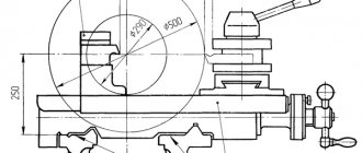
For example, when checking the accuracy of a lathe, you need to ask to make a sufficiently long cylinder (the length is equal to 4 times the diameter of the bar, the diameter of the bar is not too small), and after turning, measure the diameter of this cylinder with a micrometer at the beginning, middle and end. The difference between these values indicates poor machine geometry. Afterwards, you can grind the end of a large diameter disk - in the center you will check the plane of the resulting end with a ruler.
Figure 4. Example of part geometry deviation on a lathe
For a milling machine, you can ask to mill a rectangular prism, with its upper plane processed by the end of the cutter. To successfully carry out such checks, you should use a new and strong tool in order to prevent the cutter from bending.
Figure 5. Example of part geometry deviation on a milling machine
When processing these surfaces, observe how the machine operates - the noise from the spindle, the smoothness of the cutting. On good equipment there should be no problems. During operation of the machine there should be no sharp impacts, crunches or whistles of the mechanisms.
If possible, ask for a part that is similar to what you require. Check the quality of surfaces and deviations from the geometric characteristics of the product. This will help you quickly check the machine for technological accuracy.
Checking the mechanics, guide lubrication system and coolant
Check the functionality of the limit switches - if any of them are disabled, broken or not working - then either the mechanism has already crashed in this direction or this will happen in the near future.
On CNC machines, make sure the tool changer is working properly. Changing instruments should occur without sudden sounds or impacts. For universal equipment, check the condition of the tool holder and axial tool mounting cones.
Check the condition of the hydraulic system hoses and the operation of the hydraulic pump. Make sure there are no signs of oil leaks anywhere. Oil pump filters must be in good condition.
Be sure to check that there is an oil film on all guides and lead screws. Elements on which there is no oil film are subject to excessive wear. Sufficiently viscous oil (VG-68) must be used for lubrication.
The coolant poured into the tank should be of good concentration - opaque and oily to the touch (9-10%). It is unacceptable if ordinary water is used when processing parts or if there are traces of corrosion in the coolant tank.
Electrical check
Electrics are an integral part of modern machines. Basically only requires visual inspection. Key points requiring clarification:
- There should be no traces of heating or burning on electrical equipment.
Figure 6. This transformer will soon burn out
- If any electrical appliances have fans installed, they must be in good working order. A faulty fan means the element is overheating. Prolonged overheating of the element reduces its service life. Heavily contaminated fan filters are not acceptable.
Figure 7. The fan seems to be there, but it’s not there
- Availability of an electrical circuit for the machine and its correspondence to reality. Check the presence and correct numbering of the wires; this will help save time during repairs. Also, do not forget to ask about the rest of the documentation for the mechanical parts and hydraulic system.
- Check the sealing of all armored sleeves and proper grounding. A short circuit can have dire consequences.
Figure 8. Poor cable insulation.
- Make sure the electrical cabinet is clean. Especially when choosing a wood cutting machine. Fine dust can cause serious damage to the CNC system.
- On CNC equipment, check the load on the axes and spindle of the machine while it is running. For universal machines
Checking your CNC lathe for errors
The selection of CNC machines must be made with special care. In the ALARM HISTORY menu, check what errors the machine has had in the past. It is worth paying attention to servo amplifier errors, encoder errors and episodes of exceeding permissible loads.
If the error history menu contains information for a short period, this indicates that it was intentionally cleaned. The operating time of the CNC rack should also not be zero.
It also happens that there are permanent errors on the machine that are not reset. The seller may claim that they do not affect anything. But be careful, the seller always wants to sell the machine quickly.
Is it worth buying used machines?
Definitely worth it if the machine is in acceptable condition and fits your needs. Used devices are several times cheaper than new ones and, if used correctly, will last quite a long time. You can buy a used machine on Avito for ridiculous money and use it successfully (if you didn’t buy scrap metal). The choice of machines on various trading platforms is very solid. The main mistake is made by purchasing equipment that is poorly suited for the required tasks. Don't take the first equipment you come across, think 10 times.
Another tip is to buy fairly popular models for which you can easily find components. Make sure that the machine manufacturer still exists; there you can order new and high-quality components if they break down. If you want to be sure of the serviceability of the equipment and its reliability, then order a machine inspection service from our company: diagnostics of CNC machines
Figure 9. Checking the machine with a stethoscope.
Buying a used machine is always a lottery. Even the most conscientious seller will not be able to guarantee full functionality of the equipment for at least a year. And new machines break down. There are defects that were introduced at the production stage. And you can't do anything about it. In production, you always need to budget time and money for repairs.
And of course, you need to bargain skillfully, since buying used machines allows you to do this, for this you need to give the impression of a “knowledgeable specialist” and have a little charisma. Don't hesitate to ask for a price reduction for obvious problems.
Finally, I will say that after purchasing a machine, do not skimp on its transportation. Most defects occur during shipping and handling. Set aside money in advance for this too.
Good equipment to you!
Check 9. Parallelism of the headstock spindle axis to the direction of longitudinal movement of the caliper
Test method
A cylindrical mandrel is tightly inserted into the hole in the headstock spindle.
An indicator is installed on the support so that its measuring rod touches the surface of the mandrel:
a) along its upper generatrix;
b) along its lateral generatrix. The support moves along the bed.
In each section of the test, measurements are taken along two diametrically opposite generatrices (when the spindle is rotated 180°).
The error is determined by the arithmetic mean of the results of both measurements in a given plane.
Permissible deviations:
a) When measured in a vertical plane:
- 0.030 mm over a length of 300 mm - for machines with the largest processing diameter up to 800 mm
- 0.050 mm over a length of 300 mm - for machines with the largest processing diameter up to 1600 mm
- 0.060 mm over a length of 300 mm - for machines with the largest processing diameter up to 3200 mm
- 0.080 mm over a length of 300 mm - for machines with the largest processing diameter up to 6300 mm
b) When measuring in the horizontal plane:
- 0.012 mm over a length of 300 mm - for machines with the largest processing diameter up to 400 mm
- 0.015 mm over a length of 300 mm - for machines with the largest processing diameter up to 800 mm
- 0.020 mm over a length of 300 mm - for machines with the largest processing diameter up to 1600 mm
- 0.025 mm over a length of 300 mm - for machines with the largest processing diameter up to 3200 mm
- 0.060 mm over a length of 300 mm - for machines with the largest processing diameter up to 6300 mm
The free end of the mandrel can only deviate upward and towards the front caliper cutter.
Check 10. Parallelism of the direction of movement of the headstock spindle axis caliper slide
Test method
A cylindrical mandrel is tightly inserted into the hole of the headstock spindle
An indicator is installed on the caliper slide so that its measuring rod touches the surface of the mandrel along its lateral generatrix.
The rotating part of the caliper is installed in such a position that when the slide moves, the indicator readings at the ends of the mandrel are the same. After this condition is reached, the indicator is rearranged so that its measuring rod touches the surface of the mandrel along its upper generatrix
The caliper slide moves along the upper guides over the entire stroke length.
Permissible deviations:
- 0.03 mm on slide stroke length up to 100 mm
- 0.04 mm on slide stroke length up to 300 mm
- 0.05 mm on slide stroke length up to 500 mm
Check 11. Radial runout of the axis of the center hole of the tailstock, if used
- a rotating center mounted in the quill;
- rotating spindle with faceplate.
Test method
A cylindrical mandrel is tightly inserted into the center hole of the tailstock.
An indicator is installed on the machine so that its measuring rod touches the surface of the mandrel
The mandrel is rotated.
The measurement is taken at the end of the spindle (quill) and at a distance of l=300 mm from it.
Permissible deviations:
a) When measuring at the end of the quill
- 0.02 mm - for machines with the largest processing diameter up to 1600 mm
- 0.03 mm - for machines with the largest processing diameter up to 3200 mm
- 0.04 mm - for machines with the largest processing diameter up to 6300 mm
b) When measuring at a distance l=300 mm from the end of the quill:
- 0.03 mm - for machines with the largest processing diameter up to 1600 mm
- 0.05 mm - for machines with the largest processing diameter up to 3200 mm
- 0.06 mm - for machines with the largest processing diameter up to 6300 mm
Check 13. Parallelism of the quill movement to the direction of the longitudinal movement of the caliper
Test method
The quill is pushed into the tailstock and clamped.
An indicator is installed on the support so that its measuring rod touches the surface of the quill at points located on its upper generatrix and on its side generatrix.
The quill is released, extended to half its maximum extension and clamped again.
The caliper is moved longitudinally so that the indicator rod again touches the quill generatrix at the same point as when initially installed.
The error is determined by the algebraic difference in the indicator readings.
Permissible deviations:
a) When measured in a vertical plane:
- 0.03 mm over a length of 100 mm - for machines with the largest processing diameter up to 800 mm
- 0.04 mm over a length of 100 mm - for machines with the largest processing diameter up to 1600 mm
- 0.06 mm over a length of 300 mm - for machines with the largest processing diameter up to 3200 mm
- 0.08 mm over a length of 300 mm - for machines with the largest processing diameter up to 6300 mm
b) When measuring in the horizontal plane:
- 0.01 mm over a length of 100 mm - for machines with the largest processing diameter up to 400 mm
- 0.012 mm over a length of 100 mm - for machines with the largest processing diameter up to 800 mm
- 0.015 mm over a length of 100 mm - for machines with the largest processing diameter up to 1600 mm
- 0.03 mm over a length of 300 mm - for machines with the largest processing diameter up to 3200 mm
- 0.04 mm over a length of 300 mm - for machines with the largest processing diameter up to 6300 mm
When extending, the end of the quill can only deviate upward and towards the cutter of the front caliper.
(Changed edition, Amendment No. 1).
Check 12
A
S
| Largest | Tolerance µm | ||
| diameter mm | Class | ||
| accuracy | |||
| What is being checked | Test method | products of mouth and water | machine |
| rod J | |||
| And | above the camp D | N | P |
Accuracy of stump fixation during repeated turns at each position
a) incisal head,
b) turret head
Indicator 1 is mounted on spindle 2 so that its measuring tip is perpendicular to the point of contact
a) the surface of a rectangular mandrel 3, fixed in the cutting head 4, and was located at a distance of 150 mm from its axis,
b) cylindrical
the surface of the mandrel 5, fixed in the turret 6, and was
located at a distance L from its edge or end, with a fixed position of the heads
Heads rotate 360°
The deviation is determined by the difference in the indicator readings at the initial position of the heads
a
| Up to 200 | Up to 800 | 32 | 20 |
| b | |||
| Up to 32 | Up to 320 | 12 1 8 L = 100 mm | |
| St 32 | St 320 | 20 I | I 12 |
| up to 80 | up to 500 | L = 200 mm | |
| St 80 | St 500 | 32 | 1 20 |
| up to 200 | up to 800 | L = 300 mm |
Continuation
| Largest | Tolerance, µm | |
| diameter, mm | Class accuracy machine | |
| What is being checked | Test method | product installed above the bed, D |
| rod d | N | P |
and upon returning them to their original position after turning 360°.
The deviation is defined as the largest value of the results of five measurements.
All positions of the cutting and turret heads are checked
Check 13 (for machines that do not have a turret clamping mechanism)
| Largest | Tolerance, µm | ||
| What check | diameter, mm | Class accuracy machine | |
| Test method | product installed above the bed, D | ||
| rushes | rod d | N | P |
Constancy of the position of the turret in the bearing and locking device
An indicator 1 is installed on the stationary part of the machine so that its measuring tip is perpendicular to the point of contact with the cylindrical surface of the mandrel 2, fixed in the turret 3, and is located at a distance L from its end or edge.
The turret head is acted upon by a force P - 5 kgf applied on the shoulder Lu sequentially in the direction of rotation of the head and in the opposite direction.
The displacement at each position of the turret is determined as the algebraic difference between the indicator readings under load +P and -P.
All positions of the turret are checked
Up to 12
St. 12 to 32
St. 32 to 80
St. 80 to 200
| Up to 200 | 10 | 8 |
| D—100 mm | Lt = 300 mm | |
| St. 200 | 10 | 10 |
| up to 320 | L— 100 mm | Li = 300 mm |
| St. 320 | 25 | 16 |
| up to 500 | L = 200 mm | L1 - 500 mm |
| Over 500 | 40 | 25 |
| up to 800 | L - 300 mm | Li = 500 mm |
Check 14
With automatic longitudinal feed
With automatic cross feed
| Maximum diameter, mm | |||
| What is being checked | Test method | rod j | products, installed desired |
| A | above bed D |
Tolerance, µm
Class
accuracy
machine
N
P
Accuracy of switching off with stops (when switching on again) the automatic longitudinal feed of the turret and transverse calipers and the automatic transverse feed of the transverse caliper and turret
On the stationary part of the machine, install indicator 1 so that its measuring tip is perpendicular at the point of contact of the edge of the turret 2 and the edge of the cutting head of the transverse support 2, brought to the stop on the automatic feed.
Then the calipers being checked are moved away from the stop and the automatic feed is turned on again until the stop.
Deviation is defined as the largest difference in indicator readings in five measurements
| Up to 12 | Up to 200 |
| St. 12 | St. 200 |
| up to 32 | up to 320 |
| St. 32 | St. 320 |
| up to 80 | up to 500 |
| St. 80 | Over 500 |
| up to 200 | up to 800 |
20
Check 16. Lead screw axial runout
Test method
The indicator is installed so that its measuring rod touches the end of the screw at its center or the surface of the ball inserted into the center hole of the screw (in this case, the indicator measuring rod is flat).
The screw, loaded in the axial direction, is driven into rotation.
The check is carried out both with right and left rotation of the screw (with the corresponding directions of the axial load created by the working pressure between the screw and the nut during the longitudinal movement of the caliper).
Permissible deviations:
- 0.010 mm - for machines with the largest processing diameter up to 400 mm
- 0.015 mm - for machines with the largest processing diameter up to 800 mm
- 0.020 mm - for machines with the largest processing diameter up to 1600 mm
- 0.025 mm - for machines with the largest processing diameter up to 3200 mm
- 0.030 mm - for machines with the largest processing diameter up to 6300 mm