Checking pressure gauges: rules and procedure
Checking pressure gauges: basic rules
A pressure gauge is used to monitor pressure levels in industrial tanks and vessels. In order for it to work accurately and show the correct data, it must be regularly checked for serviceability.
Regulations for checking pressure gauges: terms and conditions
Checking the readings of working instruments with their subsequent sealing, in accordance with the current GOST, is carried out at least once a year. In addition, the enterprise must carry out a scheduled inspection with a control pressure gauge at least once every six months. Each such check must be accompanied by a corresponding journal entry.
If the necessary control device is not available, you can check it with a sealed working pressure gauge. The main thing is that its scale and accuracy class coincide with the pressure gauge being tested.
How to check a gas pressure gauge
In general, the test consists only of comparing the data of the pressure gauge being tested with the readings of the control device or calculating the current gas pressure, then measuring it using a pressure gauge and comparing the data. To do this, you only need a control pressure gauge and a thermometer. If we describe this procedure in more detail, it looks like this:
- install the pressure gauge sensor into the container through a special fitting;
- when the pressure value is recorded, remove the pressure gauge and install a control device in its place;
- After comparing the readings of the two instruments, check the accuracy of the instrument readings;
- if the instrument readings do not coincide with the reference pressure gauge, it is necessary to adjust it so that under the same operating conditions the instruments show the same pressure values;
- there are adjusting bolts on the pressure gauge body, with the help of which adjustments need to be made;
- with an electronic analogue the actions are the same, only you need to take into account that this device has inertia, so the readings must be held for 8 to 10 s.
If there is no reference device, you must first calculate the working pressure using the formula P2=T2•P1/T1:
- this will require a vessel of a volume that is known or can be measured, containing air at normal atmospheric pressure and room temperature;
- the vessel is hermetically sealed and gradually heated;
- then the pressure inside the vessel is simply calculated using the formula, where T1 and T2 are the initial and final air temperatures in the vessel, and P1 is the atmospheric pressure.
- if the instrument readings do not coincide with the calculation, then it is necessary to adjust it to the data obtained during the calculation.
All types of monometers from our company
nvph.ru
All about verification
Now let's talk about how pressure gauges are checked, the timing and frequency of the devices being checked, and what rules should be followed.
If calibration of pressure gauges is carried out in laboratory conditions, then according to the rules it includes the following steps:
- visual diagnostics;
- setting the scale needle to the zero mark;
- diagnostics of the position of the arrow on this mark;
- The verification methodology includes identifying the main error.
Frequency and timing
As for frequency, at enterprises it is usually entered into the appropriate audit log. But since ordinary car enthusiasts usually do not keep a log of control checks of pressure gauges, this information can be recorded separately in a notebook. The frequency of diagnostics may vary depending on the device manufacturer; according to the rules, on average it can range from 12 to 60 months (the author of the video is the Avtozvuk.ua channel - Avtozvuk Database).
Instructions for checking the pressure gauge yourself
Now briefly about how to check the pressure gauge yourself. Before starting measurements, it is necessary to carry out a visual diagnosis of the device. Carefully inspect the case for cracks, chips, gaps or other mechanical damage that could lead to the device not working. If you notice traces of damage, and the device basically does not work, then further diagnostics will most likely be useless. It will be much easier to buy a new device than to waste time and resources on repairing the old one.
As for directly diagnosing values, it is carried out as follows:
- First you need to diagnose the pressure, but for such a check you will need a so-called reference device, that is, a device whose readings you are confident in. If the power unit or, for example, in the tires of a car, then measure the pressure first with one device, and then with another. If the readings of your device do not coincide with the reference one, you need to adjust it. You need to ensure that the readings from the measurements using the two devices match.
- To make adjustments, special adjustment screws must be located on the device body. If you are using an electronic device, then the principle here is generally similar, but it should be taken into account that devices of this type have inertia. Accordingly, the readings will need to be held from 8 to 10 s.
- If you do not have a reference device, you can diagnose the correctness of the readings using calculations. You will need a vessel whose volume you know exactly, and the air in it is at atmospheric pressure, the level of which is measured by a barometer, and the temperature should be room temperature. The vessel should be tightly closed and heated slightly to increase the temperature and pressure, which should also be measured. You should calculate the pressure reading in the vessel itself by dividing the final heating temperature with the initial room temperature. After this, the result should be multiplied by the atmospheric pressure.
- If the device’s performance at this temperature does not coincide with those that were calculated, it is necessary to adjust the device so that the device shows the value that was obtained during the calculations. When you make calculations, take into account the fact that the temperature level should be measured in Kelvin, and for this, the number 273 should be added to the resulting degrees Celsius. In most cases, the scales on devices are graduated in kg/cm2, accordingly, the calculation will be carried out in pascals or mmHg. Therefore, to obtain more accurate results, it will be necessary to convert all units and only after these steps make comparisons.
If the adjustment does not give the required results and the readings obtained from the device are not correct, you can try to have the device diagnosed by specialists. But if even in laboratory conditions it was not possible to obtain the desired result, then the only way out is to repair the device or replace it.
Loading …
Requirements for pressure gauges - Information and documents on labor protection and industrial safety
Requirements for pressure gauges
Each vessel and independent cavities with different pressures must be equipped with direct-acting pressure gauges. The pressure gauge is installed on the vessel fitting or pipeline between the vessel and the shut-off valve. Pressure gauges must have an accuracy class of at least: 2.5 - at a vessel operating pressure of up to 2.5 MPa (25 kgf/cm2), 1.5 - at a vessel operating pressure above 2.5 MPa (25 kgf/cm2).
The pressure gauge must be selected with a scale such that the limit for measuring working pressure is in the second third of the scale. The owner of the vessel must mark the pressure gauge scale with a red line indicating the operating pressure in the vessel. Instead of the red line, it is allowed to attach a metal plate painted red to the pressure gauge body and tightly adjacent to the glass of the pressure gauge. The pressure gauge must be installed so that its readings are clearly visible to operating personnel. The nominal diameter of the body of pressure gauges installed at a height of up to 2 m from the level of the observation platform must be at least 100 mm, at a height of 2 to 3 m - at least 160 mm. Installation of pressure gauges at a height of more than 3 m from the site level is not permitted. A three-way valve or a device replacing it must be installed between the pressure gauge and the vessel, allowing periodic checking of the pressure gauge using a control valve. In necessary cases, the pressure gauge, depending on the operating conditions and the properties of the medium in the vessel, must be equipped with either a siphon tube, or an oil buffer, or other devices that protect it from direct exposure to the medium and temperature and ensure its reliable operation. On vessels operating under pressure above 2.5 MPa (25 kgf/cm2) or at ambient temperatures above 250°C, as well as with explosive atmospheres or hazardous substances of the 1st and 2nd hazard classes according to GOST 12.1.007-76 Instead of a three-way valve, it is possible to install a separate fitting with a shut-off valve for connecting a second pressure gauge. On stationary vessels, if it is possible to check the pressure gauge within the time limits established by the Rules by removing it from the vessel, the installation of a three-way valve or a device replacing it is not necessary. On mobile vessels, the need to install a three-way valve is determined by the vessel design developer. Pressure gauges and pipelines connecting them to the vessel must be protected from freezing. The pressure gauge is not allowed for use in cases where: there is no seal or stamp with a mark indicating verification; the verification period has expired; when it is turned off, the arrow does not return to the zero scale reading by an amount exceeding half the permissible error for this device; the glass is broken or there is damage that may affect the accuracy of its readings. Checking of pressure gauges with their sealing or branding must be carried out at least once every 12 months. In addition, at least once every 6 months, the owner of the vessel must carry out an additional check of the working pressure gauges with a control pressure gauge and record the results in the control check log. In the absence of a control pressure gauge, it is allowed to carry out an additional check with a proven working pressure gauge that has the same scale and accuracy class as the pressure gauge being tested. The procedure and timing for checking the serviceability of pressure gauges by maintenance personnel during the operation of vessels should be determined by the instructions for the operating mode and safe maintenance of vessels, approved by the management of the organization that owns the vessel.
____________________________________________________________ Rules for the design and safe operation of pressure vessels (approved by Resolution of the State Mining and Technical Inspectorate of the Russian Federation dated June 11, 2003 N 91)
naine.ru
Why do pressure gauges have different markings?
The same pressure gauge can be used to measure liquid and gas pressure. This becomes acceptable only if each of its structural elements is resistant to these types of environments. When a pressure gauge can be used in limited conditions, specialized symbols are applied to the scale of the device, which notify about the intricacies of operating a particular device. Detailed information about the influence of which particular environment can be measured by the device is indicated in the manufacturer’s data sheet.
When measuring small indicators, a membrane is used as a sensitive element. Due to the large area of the membrane, even a small influence on it provokes a clear transformation of the membrane. Such a change is communicated using the thrust of the rotary switch mechanism, and the device demonstrates exactly the pressure that actually exists at any given moment in time. To connect the pressure gauge to an aggressive environment, specialized membranes are used. The bodies of devices are often painted in different colors, and this is no coincidence: blue devices are used to measure oxygen pressure, yellow ones are used for ammonia pressure gauges, white ones are for acetylene pressure gauges, dark green ones are used for hydrogen, grayish-green ones are used for chlorine.
The body of products designed for propane and other flammable gases is painted red. The black color of the body is for pressure gauges designed for the use of non-flammable gases. Oxygen-type devices must be degreased, since sometimes minor contamination of the fitting, when connected to oxygen, can cause a flame and even an explosion. In pressure gauges for acetylene, the presence of copper alloys in the measuring device is not allowed, due to the fact that during contact with acetylene there is a risk of formation of explosive acetylene copper.
Pressure gauges checking proper operation - Chemist's Handbook 21
Metal pressure gauges are simple in design and quite reliable in operation. For periodic monitoring of the serviceability of pressure gauges, proven control pressure gauges are used. The pressure gauge in use on the device must have a seal with the date of inspection and testing. [p.44]
Each autoclave must be equipped with a working, sealed pressure gauge. Each pressure gauge must be checked and sealed at least once every six months (regardless of the period of operation). A red line should be drawn on the pressure gauge scale or, instead of it, a metal plate painted red should be strengthened (soldered), tightly adjacent to the glass of the pressure gauge and installed on the division corresponding to the maximum permissible pressure in the autoclave. [p.764]
Flushing of main air pipelines Major cleaning of a piston compressor Major cleaning of a rotary compressor during single-shift operation Major cleaning of a rotary compressor during two-shift operation Cleaning of intermediate refrigerators Checking the serviceability of pressure gauges Checking the presence of water in the sealing box of a rotary compressor Changing the oil in the sealing box and washing it
[p.130]
Pressure gauges and thermometers must be in good working order - with intact glass and a body without dents. The operating pressure range of the oil pump should be in the first half of the pressure gauge scale. If, for example, a centrifuge oil unit operates in the pressure range of 5-20 kgf/cm2, then the pressure gauge scale should be designed for 40 kgf/cm2. The body of the pressure gauge and thermometer must have a seal and a sign of a state inspector, indicating that the device has passed an annual test. [p.158]
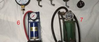
The procedure for working on the test bench is as follows.
After checking the serviceability of the stand and preparing it for work, a safety valve 8 is installed on one of the workplaces. Air is pumped into the receiver with a compressor to the operating pressure of the safety valve. Slowly open the valve in front of the valve and check the tightness of the seal between the valve and the seat. If there is a lack of tightness, the necessary repairs to the valve are made (changing the sealing ring, cleaning the surfaces, adjusting the spring force, etc.). After repair, adjust the valve to the required pressure by tightening or loosening the spring adjusting screw. The response pressure is determined by control pressure gauge 3 at the moment of the characteristic pop of the valve with a gradual increase in air pressure in the receiver. In this case, the receiver is necessary to generate a pop that makes it easier to adjust the valve. Receiver capacity is recommended to be at least 40 liters. After adjusting the valve, the adjusting screw is secured with a locknut. [p.55]
After completing the listed work, they begin to check the operation of instrumentation.
For spring pressure gauges, the return of the needle to zero is checked after communicating it with the atmosphere and releasing the gas pressure through a three-way valve. If the pressure gauge readings are inaccurate, a control pressure gauge is installed on the three-way valve and, using the three-way valve, pressure is simultaneously measured with the control and working pressure gauges. If the readings of the pressure gauges turn out to be different, then the working pressure gauge is replaced with a working one. Next, they begin to check the readings of the pressure gauge, which measures the pressure difference across the filter. If the pressure drop across the filter is higher than the permissible 100 mm water. Art. (1000 Pa), then the filter must be cleaned. [p.146]
The entire territory of the installation, as well as the sites of the reactor unit, are cleared of oil products and foreign objects, which ensures normal working conditions for the operating personnel at the installation. The serviceability of the steam extinguishing system is checked (steam risers in the twin chambers of furnaces, in pump rooms), the serviceability of the risers, the presence of fire extinguishers, fire blankets, sand, etc. The fans of all ventilation devices in production pump rooms and rooms must be tested and brought into working condition blowers and compressors. Pressure gauges are checked, as well as safety valves installed in devices operating under pressure above 0.7 ati. Safety valves that have defects (the lever does not move, or the seal is broken), or that have expired are not allowed to be used. [p.137]
When setting up devices and assessing the quality of operation of the installation, they are guided by the general methods outlined above for determining the condition and serviceability of the installations and their individual elements.
Pressure and boiling and condensation temperatures are determined by pressure gauges, which are installed during testing on special tees of the compressor discharge and suction valves. Techniques for installing pressure gauges, methods for controlling temperature conditions and setting up automation devices are outlined in the description of the start-up of small installations after installation. [p.197]
After removing the valves, check the condition of the working surfaces of the cylinders through the valve seats. If there are scratches and burrs, disassemble the piston group, clean the cylinder bore with a thin sanding cloth, and clean the rings and grooves on the piston. Then connect all the pipelines and devices that were disconnected for purging, clean the filters on the lubrication system, and check the tightness of the threaded connections on the compressor. Replace the pressure gauges used during purging with permanent ones, check the serviceability of the safety valves and prepare the compressor for load testing. Load tests are used to check the performance of all components and systems of the compressor under operating conditions. After starting, they begin to load the compressor, making sure that all components are operating normally at idle. At first
www.chem21.info
Pressure gauge check log
JOURNAL OF CONTROL CHECKS OF MANOMETERS
___________________________________________________
(Business name)
___________________________________________________
Started ___________________ 20___
Finished ________________ 20___
RULES FOR THE CONSTRUCTION AND SAFE OPERATION OF STEAM AND WATER BOILERS
(Approved by Gosgortekhnadzor of Russia on May 28, 1993)
Extraction
6.4. Pressure gauges
6.4.1. Each steam boiler must be equipped with a pressure gauge indicating steam pressure.
On steam boilers with a steam output of more than 10 t/h and hot water boilers with a heating output of more than 21 GJ/h (5 Gcal/h), the installation of a recording pressure gauge is required.
The pressure gauge must be installed on the boiler drum, and if the boiler has a superheater, also behind the superheater, before the main valve.
On direct-flow boilers, the pressure gauge must be installed behind the superheater, in front of the shut-off valve.
Installation of a pressure gauge on steam superheaters of locomotive, locomotive, fire tube boilers and vertical type boilers is not required.
6.4.2. Each steam boiler must have a pressure gauge installed on the supply line in front of the body that regulates the water supply to the boiler.
If several boilers with a steam capacity of less than 2.5 t/h each are installed in the boiler room, it is allowed to install one pressure gauge on the common supply line.
6.4.3. When using a water supply network, instead of a second feed pump, a pressure gauge must be installed in the immediate vicinity of the boiler on this water supply network.
6.4.4. On a water-switched economizer, pressure gauges must be installed at the water inlet, up to the shut-off valve and safety valve, and at the water outlet, up to the shut-off valve and safety valve.
If there are pressure gauges on the common supply lines to the economizers, installing them at the water inlet to each economizer is not necessary.
6.4.5. On hot water boilers, pressure gauges are installed at the water inlet to the boiler and at the outlet of heated water from the boiler to the shut-off valve, on the suction and discharge lines of circulation pumps located at the same height, as well as on the boiler supply lines or heating network feed lines.
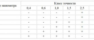
6.4.6. The accuracy class of pressure gauges must be no lower than:
files.stroyinf.ru
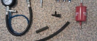
Purpose and device
The pressure of liquefied blue fuel is quite high: this simplifies its transportation and operation. As it is supplied to the consumer (gas stove, boiler, welding machine), the pressure indicator must be noticeably reduced. The transformation process takes place inside a special device - a gas reducer.
For example, the propane-butane mixture inside the cylinder has a pressure of approximately 16 bar. Consumers are designed for a regime of several tens of millibars. In this case, the fuel must come from the tank in stable parameters, without jumps and drops. This task is assigned to the gearbox. A device of this type is included in the design of all cylinder modules (domestic and industrial), ensuring their safe operation.
The main components of any gearbox are:
- spring for locking;
- membrane;
- reducing valve.
The spring force is aimed at closing the valve, which leads to the cessation of gas supply. In contrast to this inertia, the membrane acts to open the valve. The final point in this “confrontation” comes from reduced fuel. If its pressure drops below a certain value, the membrane force becomes dominant, which leads to the opening of the passage. Along with the basic equipment, some models of the gas reducer include a valve and a pressure gauge, which allow more precise control of the indicators of the supplied gas mixture.
Technique for checking technical pressure gauges
Checking gas pressure gauges
Gas pressure gauges must be checked and subsequently sealed or branded at least once every 12 months.
At least once every 6 months, the owner of the vessel is obliged to carry out an additional check of the working pressure gauges with a calibrated pressure gauge and record the results in the control check log. When using a reference pressure gauge, it is allowed to carry out an additional check using a proven working pressure gauge that has the same scale and accuracy class as the pressure gauge being tested.
The procedure and timing for checking the serviceability of pressure gauges by maintenance personnel during the operation of vessels should be determined by the instructions for the operating mode and safe maintenance of vessels, approved by the management of the organization that owns the vessel. The following terms are used in these Guidelines:
1.1. Calibration of measuring instruments (calibration work) is a set of operations performed to determine and confirm the actual values of metrological characteristics and (or) suitability for use of a measuring instrument that is not subject to state metrological control and supervision.
1.2. Calibration means - standards, settings and other measuring instruments used during calibration in accordance with established rules.
1.3. Calibration certificate is a document certifying the fact and results of calibration of a measuring instrument, which is issued by the organization performing the calibration.
1.4. Calibration marks are technical devices intended for applying a mark imprint to measuring instruments, additional devices or technical documentation for the purposes of:
- certification that measuring instruments have metrological characteristics that meet the established technical requirements;
- exceptions when it is necessary to access the adjustment (adjustment) devices of measuring instruments;
- sealing unsuitable measuring instruments;
- cancellation of an existing mark (cancelling marks).
1.5. The quality manual for the organization and execution of calibration work (hereinafter referred to as the “Quality Manual”) is a document that establishes the goals, methods and procedures that allow the metrological service or calibration laboratory to solve problems determined by the regulations on them.
1.6. The quality of calibration of measuring instruments is a set of calibration characteristics that determine the compliance of methods, means and conditions with the requirements established in regulatory documents on calibration.
Monometers from our company
nvph.ru
Requirements for pressure gauges in the boiler room
A parameter such as pressure is fundamental for the normal and uninterrupted operation of the boiler room. Too much pressure threatens to rupture pipelines and boilers, and critically low pressure can cause boiling of the coolant in the boiler and cavitation in pumps. Therefore, pressure gauges are one of the most important components of boiler room equipment in terms of safety. Therefore, it is simply necessary to ensure timely maintenance and, if necessary, timely repair of pressure gauges. Controlling organizations pay very close attention to the condition of spring pressure gauges and their compliance with the requirements of the Rules for ensuring industrial safety during the operation of steam boilers with a steam pressure of no more than 0.07 MPa (0.7 bar) and hot water boilers with a water heating temperature of no higher than 115° WITH. Here are the main excerpts from the Rules on the configuration, placement and requirements for pressure gauges in the boiler room (source - gospromnadzor.by)
clause 243 Pressure gauges installed on boilers and pipelines within the boiler room must have an accuracy class of at least 2.5; - this item is only suitable for so-called “small” boilers (steam boilers with a pressure of up to 0.7 bar and hot water boilers with a temperature of up to 115°C); for “large” boilers, the accuracy class of pressure gauges that must be adhered to will depend on the measured pressure.
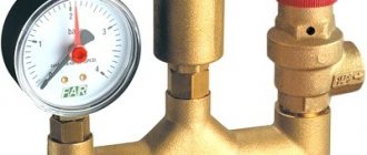
On the pressure gauge body there is a red metal plate indicating the permitted pressure. The operating pressure is in the second third of the scale. The pressure gauge complies with the requirements of the Rules
item 244 Pressure gauges must be selected with a scale such that at operating pressure their needle is in the second third of the scale; - that is, for example, if the working pressure in the measured area is 0.4 MPa, then it is necessary to select a pressure gauge with a range of 0-0.6 MPa (second third of the scale), and if the working pressure is 0.2 MPa, then it is already necessary to take a pressure gauge with range 0-0.4 MPa (0.6 MPa will not work). For both cases, it is naturally incorrect to install a pressure gauge with a range of up to 1 MPa.
p.245 A red line is drawn on the pressure gauge scale according to the division corresponding to the permitted pressure in the boiler, taking into account the additional pressure from the weight of the liquid column. Instead of the red line, it is allowed to attach or solder to the pressure gauge body a metal plate painted red and tightly adjacent to the glass of the pressure gauge above the corresponding scale division. It is prohibited to paint a red line on glass; - this point is very often violated by careless boiler room staff, since in order to avoid unnecessary movements, the red line is applied specifically to the glass, and sometimes not even with paint, but with a marker.
p.246 The pressure gauge is installed so that its readings are visible to the operating personnel, and the pressure gauge must be in a vertical plane or tilted forward up to 30°. The pressure gauge must have a three-way valve. — a three-way valve at the pressure gauge must be present to shut it off, purge or connect a control pressure gauge.
clause 247 The diameter of pressure gauge housings installed from the level of the pressure gauge observation platform at a height of up to 2 m must be at least 100 mm, at a height from 2 to 5 m - at least 160 mm and at a height of more than 5 m - at least 250 mm .
The most important requirements for pressure gauges are found in paragraph 250.
clause 250 Pressure gauges are not allowed for use in cases where: there is no seal or stamp on the pressure gauge indicating verification; the pressure gauge verification period has expired; when it is turned off, the pressure gauge needle does not return to the zero scale reading by an amount exceeding half the permissible error for a given pressure gauge; glass is broken or there is other damage that may affect the accuracy of the readings.
p.251 On hot water boilers and water heat recovery boilers, pressure gauges are located: at the water inlet into the boiler after the shut-off valves; at the outlet of heated water from the boiler to the shut-off valves; on the suction and discharge lines of circulation and make-up pumps at the same level.
p.254 Verification of pressure gauges with their sealing (branding) is carried out at least once every 12 months. In addition, at least once every 6 months, the organization must check working pressure gauges with a proven control pressure gauge that has the same scale and accuracy class as the pressure gauge being tested. The results of the inspection are recorded in the audit log.
Representatives of regulatory organizations pay especially zealous attention to clauses 250 and 254. This is correct, because if the pressure gauge is not verified or has damaged glass, then there is a possibility that it may display incorrect readings, or its readings will be incorrectly interpreted. And if it does not set to “0”, then such a pressure gauge must be immediately replaced or repaired.
Rules for ensuring industrial safety when operating steam boilers with a steam pressure of no more than 0.07 MPa (0.7 bar) and hot water boilers with a water heating temperature not higher than 115 ° C (as well as other Rules) can be downloaded from the official website of Gospromnadzor.
teplovichek.com
Cases when using a pressure gauge is prohibited.
If the pressure gauge does not have a seal or stamp, the verification period has expired, or the gearbox pointer does not return to the initial mark, by an amount greater than half the permissible error when turned on, then it is prohibited to use such a pressure gauge.
In addition, it is not allowed to use a device that has broken glass or other damage that could affect the accuracy of the readings.
Read also: Optimal height of a workbench in a garage
In conclusion, we note that a working pressure gauge can serve as a guarantee of safety when working with gas welding equipment.
Measuring instruments and tools require control using metric meters. Pressure gauges that analyze the pressure of liquids and gases are installed on heating boilers, gas cylinders, and used on production units. To obtain correct readings from the device and to protect company employees, pressure gauges should be checked periodically.