The tool holder is one of the most important blocks of lathes, used to secure the cutting tool. There are many modifications to the design of such a unit, intended for use in various conditions. In addition, universal tool holders for lathes are produced, which can also be used for other metal-cutting equipment. The quality of metalworking of a workpiece largely depends on the accuracy of the cutter holder.
Design and purpose of the tool holder
The tool holder is a separate unit fixed with a bolt connection, used for fastening a metalworking tool. Significantly simplifies work with workpieces and allows for maximum bore holes. Tool holders are equipped with machine blocks that move the cutter.
At the top of caliper 1, on the centering collar, there is a tetrahedral head. On one side there is a cone-shaped retainer 5 with a spring 4, on the reverse side there is a ball retainer 17 with a plug on the thread 12 and a spring 15.
A flange 5 is attached to the top of the head 13 with bolts. On the middle finger 16 inside the head there is a fist 11, which has end teeth, as well as a ratchet clutch 10, which is pressed against the end of the fist by a spring 8. The clutch easily moves along the slots of the sleeve 9, pressed into the handle 7.
Handle 7 is used to release, rotate, install and secure the head. Release is carried out by turning the handle along the thread counterclockwise. Together with the handle, the fist 11, connected to it through the teeth of the ratchet 10, also moves. When the head is released under the influence of the bevel of the fist 11, the latch itself is raised on the tab of the latch 3, the knuckle 11 turns the head, resting the wall of the cutout against the pin 14. The ball 17 is raised at the same time . In the final stage of reversal, the locking ball falls into the next socket, preliminarily securing the head.
When the handle 7 is turned in the opposite direction, the fist 11 releases the latch 3, while it falls into slot 2 and finally secures the head. The wall of the cutout rests against the pin and stops the fist 11. Subsequent rotation of the handle 7 leads to the pressing of the ratchet 10 upward with the beveled end teeth. After turning the handle, the head and cutting tool are finally secured.
Conditional division of holders for cutters
Lathe holders are divided according to several parameters.
According to the type of execution, holders are:
- with replaceable blocks;
- with an axis of rotation.
According to the location of the axis, the latest models are divided into:
- horizontal (along the spindle);
- vertical (at an angle of 90° to the spindle).
By way of changing position:
- mechanical;
- electromechanical;
- hydraulic;
- with servo drive.
By the number of places for installing cutters:
- two-position, allowing you to simultaneously fix a pair of incisors;
- four-position, allowing the simultaneous installation of four units of cutting devices on the machine.
Fastening the tool in the tool holder can be done in several ways:
- through a wedge block;
- VDI – fastening with one wedge bolt from the edge of the holder disk;
- TDC – fixation in a hole at a remote diameter of the disk.
In addition, according to the type of construction, tool holders are divided into:
- simple (“soldier”);
- rotary;
- quick-change cassette tool holders;
- universal adapters.
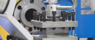
Simple tool holder
Tool holders for a lathe of a conventional “soldier” design are equipped with a special spherical gasket, which allows you to quickly install the required cutter. The cutting angle and height position are changed by rotating the gasket. The tool is secured in the tool holder with one bolt.
The advantage of this design is the ability to quickly install the cutter. The disadvantage is that the entire load is carried by a single bolt, so it must be tightened tightly and the degree of fastening must be constantly checked before turning on the machine.
When working with a machine with a tool holder of this type, you should avoid over-tightening the bolt, as there is a high probability of stripping the thread. To repair the holder, it is enough to replace the bolt, bore the holes to a different size, or install bushings with internal threads in the resulting gap.
To increase strength, bolts are made of high-strength steel, cemented to a depth of 0.6–0.8 and hardened. As a result, the bolt corresponds to a hardness grade of 50–60 HRC and is resistant to rupture.
Tool holders of the “soldier” design were often installed on Soviet-made machines. Now they have been transferred to the category of obsolete and are installed on models of light machine tools. Such tool holders hold a single tool that requires periodic change.
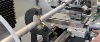
Rotary
The most common tool holders in lathes are those that allow you to place 4 cutters at once.
The machine is prepared in advance to perform several consecutive jobs without the need to replace the cutter. The maximum effect from installing a rotary tool holder in the machine is obtained when it is necessary to process parts of complex geometric shapes. Tool holders of this design look like a revolver. The main part is a disk with holes made through it, located at the same distance from each other. The holes contain slotted bushings in which the machine cutters are fixed. Thanks to the use of bushings, the cutters are installed without spacers - the cutting tool can be replaced quickly. Tool holders have spring devices that allow you to bore holes to great depths, cut internal threads, and use the machine for other work that requires high precision.
The machines currently produced also have rotary tool holders that carry up to 12 cutters. They are especially effective on CNC machines, where productivity increases significantly. Quick tool fixation and increased reliability are ensured by an electromechanical drive.
In some lathes, for example, the TC series, rotary tool holders have different design features. The tool is clamped using hardened bars or a lever-wedge device.
Quick change tool holder
If the machine is used at home for small volumes of various jobs, the cutters need to be changed frequently.
For minimal labor and time losses, it is recommended to install a quick-change tool holder with replaceable cassettes. The holders are secured in this way: an axle is screwed into the upper part of the caliper, which serves as a clamp for the tool holder. The holder is pressed on top with a nut. Included with such devices is a plate that allows you to raise the cutter higher if necessary.
The cassette is fastened using a wedge strip.
Universal adapter
Universal type cutter holders (adapters) allow you to install tools with larger dimensions on the machine than those provided for by the design.
When using small-sized machines, sometimes it becomes necessary to work with large cutters. The holder available on the machine does not allow the placement of tools of other sizes, which is why large cutters have to be ground down. To avoid boring, a special tool holder-adapter is installed on the machine, allowing you to work with tools of various sizes.
Using the tool holder
The tool holder is a separate unit of the machine, secured with bolts. It greatly facilitates the processing of parts. The use of a tool holder is especially important when accurately boring holes. The designs of tool holders are highly durable and reliable, since even a small backlash can significantly reduce the processing accuracy.
The turning tool holder is designed to accommodate the cutter in height and in the horizontal plane. The height setting of the tool holder is of great importance for the machining process. If turning is performed, the cutter is installed so that the cutting edge of the tool is higher than the center line of the machine. For boring, the cutter is placed below the center line.
Simple tool holder
The simplest design has a tool holder called a “soldier”. This device has a spherical backing that allows you to quickly secure the cutter. By rotating the spherical spacer, the cutting angle and height position are adjusted. The cutter is secured using one bolt.
On the one hand, this device of the lathe tool holder makes it possible to install the cutter in a minimum time, and on the other hand, the entire load falls on one bolt, so it must be tightly tightened. However, in an attempt to provide sufficient clamping, this bolt is often overtightened, causing the thread to quickly become unusable. As a result, the bolt breaks or the internal thread is cut off. Repairing such a tool holder consists of replacing the bolts and boring the hole to a larger size. It is also possible to install a threaded bushing into the hole. To increase the durability of bolts, they are made from strong steels, such as 12ХН3А, subjected to carburization to a depth of 0.6-0.8 mm and hardening, which makes it possible to achieve a surface hardness of 50-60 HRC. Thanks to this, the durability of bolts increases by 10-15 times compared to raw bolts made from steel 45, however, their price also increases. For most of the tool holder parts, 45 steel is used, whose hardness is in the range of 220-260 HB.
A toolholder of this design was widely used on Soviet machines. Nowadays, this design of a lathe tool holder is considered obsolete and is used only for some lightweight machines. This tool holder can only hold one tool, which requires frequent tool replacement. In industrial metalworking this leads to large losses of time.
Rotary tool holders
The cassette tool holder for a lathe, in which four tools can be simultaneously secured,
has become widespread . In this way, the machine can be prepared for four consecutive operations without changing tools. The greatest effect of this tool holder is achieved when processing parts of complex shapes.
The tool holder has a structure similar to a revolver. The main element is a large disk in which through holes are drilled at equal distances from each other. Split bushings are inserted into the holes, into which the cutters are attached. The use of bushings allows you to set the cutters in height without using spacers, so this operation is performed very quickly. Also, the device for fixing the cutters has rigid spring holders, which makes it possible to bore deep holes, cut internal threads and other precision work.
Modern machines use even more efficient tool holders, which can hold up to 12 tools simultaneously. Such tool holders are especially effective for CNC lathes; their use can significantly increase productivity. The electromechanical drive of the tool holder ensures fast and reliable tool fastening.
In lathes, for example machines of the TS16K20 series, the design of rotary tool holders has its own characteristics. The cutter is clamped using hardened bars using a lever-wedge mechanism, which significantly increases the force.
Hydraulic turrets
One of the promising areas for the development of cutters and tool holders is the development of hydraulic devices for securing cutters . Such tool holders absorb the vibration that occurs when processing the workpiece. This reduces the likelihood of tool failure. During roughing, when the cutter is under significant load, the use of hydraulic toolholders reduces tooling costs by up to 40%.
For example, lathes of the TS17 series are equipped with such tool holders.
Hydraulic tool holders have an accuracy comparable to that of electromechanical devices, and in some modes even higher. They have a larger number of positions, shorter tool change time, and a tool search direction in the shortest direction. Requires a hydraulic power station on the machine.
Recommendations for use
The tool holder belongs to the main blocks of the machine and is fixed to it by means of a bolted connection.
The use of the device is especially effective when high-precision boring is required. Their design must be reliable and highly durable. It is equally important to install the cutter correctly, because the accuracy of metalworking noticeably decreases when even a small backlash appears. The tool holder on the lathe is used to attach the cutter vertically and horizontally. Inaccurate fixation in height is considered the main cause of defects and processing defects. When turning, the cutter must be placed so that its working part is on top of the centers of the machine. When boring, the cutter should be installed at the bottom of the centering plane.
The tool holder on the universal machine is placed on the upper slide of the support. There are also rotary and transverse devices located there, and the support itself is placed on the longitudinal slide of the frame. All these units together allow you to move the cutter in all directions and rotate it along the axis, which makes it possible to use the maximum number of metalworking operations.
The holder for a heavy type roughing machine is placed on an auxiliary slide. This is explained by the too large dimensions of the cross slide: moving them manually is extremely difficult.
Principles of turning materials
Turning of materials involves processing bodies of revolution with a cutting tool moving along the axis of rotation of the workpiece.
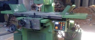
With the forward movement of the cutter, a layer of material is removed from the surface of the workpiece. Historically, processing of “round” parts was required in almost all sectors of the national economy. The first lathes were very primitive: the workpiece was rotated using a foot drive, and the cutting tool was held in the hands with emphasis on a stand. Such machines could only process soft materials, such as wood. Lathe of Peter I. At the end of the 19th century, with the advent of machines, steam and then electric engines began to be used to rotate the workpieces. An important achievement of that time was the development and introduction of cutting tool holders. The tool was fixed in a special holder, and the operator could move the holder both parallel and perpendicular to the workpiece by rotating certain handles. Such devices became known as “lathe support.”
A lathe from the early 20th century.
Modern lathes allow you to automatically move the cutting tool in specified directions. The advantages of modern lathes also include the ability to cut threads of almost any profile and a given accuracy. That’s why modern machines are called “screw-cutting lathes.”
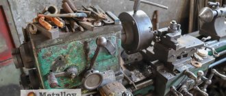
The structure and main components of a lathe.
Most lathes have almost the same design and differ only in size and location of controls. The figure shows a typical lathe and its main components. The axis of a lathe
is a virtual axis passing through the axis of rotation of the workpiece parallel to the bed.
The front stand and rear stand
are cast iron stands that serve as stands for the components and mechanisms of the machine.
Tabletop machines do not use cabinets. The bed
is the main part, the skeleton of the lathe.
The bed is usually made of all-metal by casting from cast iron. The bed is attached to the stands of the machine. The large weight of the bed reduces vibrations from the electric drive of the machine and vibrations that occur during the processing of parts. An electric drive motor is installed at the bottom of the bed, inside or behind the lathe. Electrical cabinet
- a cabinet in which elements of the electrical circuit of the machine are located, and on the outer panel there are switches for the main electric motor, a compressor for coolants, a voltmeter and indicator lights.
Headstock
- contains a set of gears, levers, shafts and mechanisms for changing the speed of rotation of the workpiece and the feed rate of the cutting tool.
The guitar
is an integral part of the headstock, which contains replaceable gears for adjusting the tool drive when cutting threads (in modern machines, changing gears is not required).
Spindle
is the main shaft for rotating the workpiece.
The spindle can accommodate fastening devices such as a chuck, a center, a collet, and the like. The chuck
is the most common workpiece fastening device.
A caliper
is a device for attaching a processing tool and moving the tool in specified directions.
The apron
is the front caliper cover.
Tailstock
is a device for fastening a workpiece (when processing in centers), or for fastening tools, such as a tap, a die when cutting threads and other devices.
Headstock
On the front surface of the headstock there are levers for switching the spindle rotation speed and cutting tool feed speed. Nameplates
are explanatory signs.
On lathes, the nameplates indicate the dependence of the speed of movement or rotation of machine components on the selected positions of the installation handles. Spindle speed knobs
- depending on the position of these knobs, the spindle rotation speed changes.
The handles can only be moved when the machine is stopped. Dividing lever
- Lever for switching the spindle speed.
The lever has three positions. In the extreme left position, the machine spindle rotates at the normal speed set by the spindle speed adjustment knobs. In the vertical (neutral) position, the spindle does not rotate. In the extreme right position, the spindle rotates at a speed 10 times lower than the set one. This lever can only be switched when the machine is stopped. Handles for setting the feed speed
- these handles set the speed of movement of the cutting tool when processing parts, as well as the movement of the cutting tool per revolution of the spindle when cutting threads.
The handles can only be moved when the machine is stopped. The spindle
is a thick-walled steel pipe. The spindle is used to transmit rotation from an electric drive, through a gear system, to the workpiece. The spindle inlet on the surface is threaded for mounting mounting chucks, and the inlet hole is cone-shaped for installing centers or other fasteners. It should be noted that for different machine models, the number and position of the rotation speed and movement adjustment handles may differ from those shown in the figure. For a specific model of lathe, you should carefully read the designations on the nameplates or read the operating instructions for the machine.
Tailstock
Tailstock
is a device for fastening a workpiece (when processing in centers), or for fastening tools, such as a tap, a die when cutting threads;
drill bits or drill chuck when drilling holes. The base
is a part of the tailstock, its skeleton.
The base and, consequently, the entire tailstock can move freely in a horizontal plane along the frame along the axis of the machine. The tailstock housing is attached to the base. The tailstock housing
is a unit containing the functional mechanisms of the tailstock.
Tailstock position adjustment screw
- designed to slightly move the tailstock body in a horizontal plane in transverse directions.
It is used in cases where it is necessary to align the center of the workpiece with the center of the tailstock (make it coaxial) or when processing conical parts. A quill
is a movable steel cylinder.
The inlet hole of the quill has a conical shape and is intended for fastening mandrels, fixtures, centers, etc., depending on the work being performed. Quill fixation handle.
When operating a lathe, vibrations may occur that lead to spontaneous movement of the quill.
To fix the quill in a given position, the fixation handle is used. Quill movement wheel
- when this wheel rotates clockwise, the quill moves out of the tailstock housing, and when the wheel rotates counterclockwise, the quill goes inside the tailstock housing.
Tailstock locking handle.
To move the tailstock along the bed, the locking handle should be released (move the handle back). To fix the tailstock, after moving it, the locking handle should be pulled towards you until it stops. In this case, the tailstock will be fixed in the desired position and will not be able to spontaneously move along the bed due to loads on the quill or parasitic vibrations.
Caliper
The lathe support is designed to secure and move the cutting tool. A rotary tool holder
is a device for securing and changing a cutting tool.
The tool holder fastening handle
is intended for changing the cutting tool.
To change the tool, the handle is turned counterclockwise (away from you), while the tightening head loosens the fixation of the tool holder and it rotates. To fix the tool holder, turn the tool holder fastening handle clockwise (towards you) until it stops. The upper slide
is a mechanism for moving the tool holder in a given direction.
The upper slide can be rotated (in a parallel plane) relative to the machine axis at a given angle. This will be discussed in detail in the topic “Processing of conical surfaces”. Top Slide Move Handle
- Rotating this handle moves the top slide horizontally.
Cross slide
- designed to move the cutting tool in a horizontal plane strictly perpendicular to the axis of the machine.
Cross slide movement handle
- rotating this handle clockwise moves the cross slide forward (towards the axis of the machine), and counterclockwise backwards (away from the axis of the machine).
Longitudinal slide
- a device for moving the cutting tool strictly parallel to the axis of the machine.
Slider Wheel
- Rotating this wheel counterclockwise moves the cutting tool horizontally from right to left, and clockwise moves it from left to right.
Screw feed switch
- used only when cutting threads with a cutter.
In all other modes of part processing, this switch is disabled. Feed switch
- multi-position lever to enable automatic movement of the cutting tool in a given direction. In position 0 - (neutral) the caliper stands still; in positions 1 or 2, the cross slide moves (forward or backward, respectively); in position 3 or 4, the longitudinal slide moves (to the left or to the right, respectively). Feed switches can have a different design, for example, have two levers. One includes longitudinal and the other transverse feed.
Drive shafts and mechanisms
To automatically move the support elements, as well as to quickly turn on and off the spindle rotation, the lathe is provided with several drive shafts and corresponding mechanisms.
The switching and switching mechanisms for various drives are located in the caliper under the apron. Spindle activation shaft
— has two handles for turning on the spindle.
One handle is located to the left of the machine operator, and the second to the right. Both handles are rigidly fixed to the shaft. When any of these handles is moved up, the machine is turned on and the spindle begins to rotate counterclockwise (working, forward rotation). In the middle position of the handles, the machine is turned off. When the handles are moved down, the spindle begins to rotate clockwise (reverse rotation). The rack
is an integral part of the mechanism for manually moving the caliper in the longitudinal direction.
When the wheel of movement of the longitudinal slide rotates, the gear wheel connected to the axis of rotation of the wheel and the gear rack engages, and the caliper moves. Feed Shaft
- This shaft is designed to automatically move the cutting tool.
The shaft has a longitudinal groove along its entire working length, which serves to engage with the movement mechanism. When the machine is running, this shaft rotates constantly. The feed switch knob turns on the mechanism of the selected movement. Threaded shaft (Screw)
- designed to drive the caliper in the longitudinal direction when cutting threads with a cutter. The rotation of this shaft occurs only in thread cutting mode.
Limbo
A limb is a ring (or flat washer) with marks printed on its surface, located at equal distances from each other.
At a certain interval, for example, every 10 marks, numbers are printed indicating a certain value of the dial graduation. The dial can be graduated in millimeters, degrees or other metric units. The figure shows a dial located on the mechanism for moving the cross slide. The rotation of the dial occurs together with the rotation of the tool movement handle. Every tenth of the risk on the dial is numbered 0, 1, 2 ..19. In total, the limb has 200 marks. In this case, when you turn the handle, for example, by 10 divisions (from 0 to 1), the working tool will move 1 millimeter. Different machines have different dial calibrations, so you should consult the operating instructions for the specific machine. If it is not possible to find out this information, then you can determine the amount of movement yourself. To do this, you should grind the part and measure the resulting size, then grind the part again by turning the handle ten divisions and again measure the size obtained after turning. The difference between the previous and last measurement will be the amount of movement of the tool when rotated by 10 divisions. The dial ring can be rotated on the mechanism axis by holding the movement handle. This may be necessary to set the reference point during processing; usually the value is set to 0.
Main types and characteristics of lathes
Lathes have certain characteristics that should be taken into account when manufacturing certain parts on them: Machining diameter over the bed D
- the maximum diameter of the workpiece that can be installed and processed on the machine.
| The distance between centers L is the maximum length of the workpiece that can be installed and processed on the machine. |
| The diameter of the spindle hole d is the diameter of the hole through which the workpiece (rod) can pass. |
More information about the types of modern machines can be found on the website
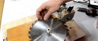
DIY holder design options
Despite the variety of designs, you can make a tool holder yourself from materials available in any garage or home workshop.
Homemade tool holders used for “garage” work are not subject to increased requirements for the accuracy of tool fastening, and you can save a significant amount for other needs. Video:
What tool holder is installed on your machine? Have you tried to make it yourself at home? Please share your opinion and experience in the comments.