Screw-cutting lathes have similar designs and similar principles of operation, regardless of the model and series of production.
The main function of this equipment is to perform turning, drilling, facing, and threading operations.
Metal and non-metallic products can be processed. Therefore, screw-cutting lathes are popular in production with a small production series.
Main types of lathes
Lathe machines are the most common in mechanical engineering and metalworking compared to metal-cutting machines of other groups.
This group includes screw-cutting lathes, turret lathes, rotary lathes, automatic and semi-automatic lathes and other machines. Screw-cutting lathes are designed for external and internal processing, including thread cutting, of single and small groups of parts.
Turret lathes are designed for processing small and large groups of complex-shaped parts made from rods or piece workpieces that require the use of a large number of tools.
Rotary lathes are designed for processing parts of various shapes, whose diameter is much greater than their length. These machines differ from other lathes in the vertical location of the axis of rotation of the faceplate, to which the workpiece is attached.
Automatic lathes are designed for processing parts from rods, and semi-automatic lathes are designed for processing parts from rods and piece workpieces.
Metal-cutting machines of domestic production have digital model designations.
The first digit in the model designation shows which technological group the machine belongs to: 1-lathes, 2-drilling and boring machines; 3-grinding machines, etc.
The second digit indicates the types of machines in the group: 1-single-spindle and 2-multi-spindle machines; 3-turret lathes; 5-turning rotary, etc.
The last two digits determine the technical parameters of the machine: the height of the centers above the bed for a lathe, the largest diameter of the processed bar for a turret lathe, etc. The presence of a letter between the numbers indicates that the machine has been modernized.
The accuracy of the machine, class, is determined by the letters: N, P, V, A, C at the end of the digital designation of the model.
According to the letters in the designation of machines, machines of normal accuracy are distinguished - class H (in most cases not indicated); increased accuracy - class P; high accuracy (precision) - class B; especially high precision - class A and especially precision (master machines) - class C.
For example, in the designation of a screw-cutting lathe model 16K20P, the number 1 indicates a group of lathes, the number 6 means the type of machine (screw-cutting lathe), the number 20 means the height of the centers in cm, the letter K means modernization of the machine, and the letter P means a high-precision machine.
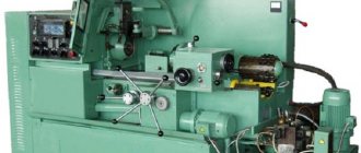
Application of CNC
Modern lathes, especially foreign ones, are numerically controlled. This allows for high processing accuracy.
The features of such machines are the following nuances:
- All moving parts of the machine are controlled by a mini control unit. The machine has a complex electrical circuit.
- All parameters of the CNC machine exactly comply with GOST and are also described in the equipment passport. Accuracy indicators, dimensions, and speed are indicated here.
- Machines of this kind can be used at home because they are small in size, but can withstand surprisingly high loads for their size.
- The equipment has an indication, as well as a display for entering information.
- Benchtop CNC machines are used for high-precision machining of small parts. At the same time, home production has a high profitability rate.
Important!
Most of these machines are produced abroad, and therefore they do not comply with Russian GOST.
Classification of screw-cutting lathes
The technical parameters by which screw-cutting lathes are classified are the largest diameter D of the workpiece or the height of the centers above the bed (equal to 0.5D), the greatest length L of the workpiece and the weight of the machine.
According to the largest diameter of the workpiece, machines are manufactured in the following series: D=100, 125, 160, 200, 250, 320, 400, 500, 630, 800, 1000, 1250, 1600, 2000 and further up to 4000 mm.
The greatest length L of the workpiece is determined by the distance between the centers of the machine. At the same D, machines are made for processing short and long parts.
By weight, lathes are divided into light - up to 0.5 t (D=100÷200 mm), medium - up to 4 t (D=250÷500 mm), large - up to 15 t (D=630÷1250 mm), heavy - 40 tons and above (D=1600÷4000 mm).
By appointment. Lightweight lathes are used in tool production, instrument making, the watch industry, and in experimental and development workshops. These machines are available with and without mechanical feed. Average lathes perform 70-80% of the total volume of turning work. The machines of this group are designed to perform finishing and semi-finishing and thread cutting.
The machines have high rigidity, sufficient power and a wide range of spindle speeds and tool feeds, which allows processing parts using modern advanced tools made of hard and super-hard materials. It is also planned to equip the machines with various devices to expand their technological capabilities, facilitating the work of the worker and improving the quality of processing. The machines have a fairly high level of automation.
Large and heavy lathes are intended mainly for heavy and power engineering and other industries. Machines of this type are less versatile than machines of the average type, and are mainly adapted for processing certain types of parts (rolls of rolling mills, railway wheelsets, turbine rotors, etc.).
Which machines should be preferred for studying? If any machine (set of drawings) is disassembled into parts, it turns out that there will be a small number of large and heavy parts. The largest number will be of medium-sized parts, which in quantity significantly exceed the number of large parts. Small parts are also significantly inferior in quantity to medium parts. Therefore, taking into account that all lathes have a standard and similar design, further attention will be paid to the study of medium-sized lathes (D = 250÷500 mm and weighing up to 4 tons) and other machines for processing medium-sized parts.
What operations can be carried out: basic technologies for processing parts
Machines are used to process surfaces with a cylinder shape; this is the main task. The pass cutter is the main tool that allows you to achieve results. A 7-12 mm allowance along the length of the parts is required when processing. This is the necessary size margin, then no additional problems arise during processing. Management doesn't deliver them either.
Several types of tools are suitable for trimming the ends of parts placed inside:
- Trimming.
- Direct passes.
- Persistent.
Persistent cutters grind and trim corners on parts while maintaining small dimensions.
Cutting small grooves on parts is another purpose of the machine. Then they take special groove tools. It is important that the spindle rotates at low speeds.
Finished products are cut using similar principles. A 2-2.5 mm diameter at the jumper at the cut point means the end of the process. The work is completed, the final stage is cutting it off from the rest of the workpiece.
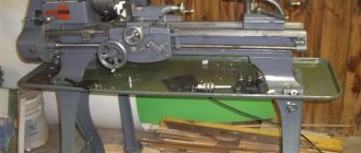
Construction of screw-cutting lathes
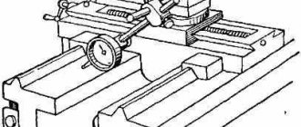
Screw-cutting lathes have a standard design for all types of lathes (Fig. 1).
Rice. 1. Design of a screw-cutting lathe: 1 - headstock, 2 - support, 3 - tailstock, 4 - bed, 5 and 9 - stands, 6 - apron, 7 - lead screw, 8 - lead roller, 10 - feed box , 11—items of replaceable gears
Main drive of the machine. Mechanism and feed box.
Main drive of the machine. The headstock contains a spindle and a gearbox (Fig. 2), which provide the workpiece with the main movement and feed at the selected cutting depth.
Rice. 2. Design of a six-speed gearbox of a lathe
The workpiece is clamped in a jaw chuck, which is attached to the spindle flange 13. Rotation from the electric motor 1, through a belt drive 2 and clutch 3, is transmitted to shaft 5. A block of three gears 7, 8, 9, located on shaft 5, using a rack and pinion drive connected to the handle 17. With this handle, the gear block is engaged with a gear wheel 4 (or 10, or 11), rigidly mounted on the shaft 6. Wheels 4 and 12 are paired, respectively, with wheels 15 and 16, which transmit torque to the spindle through a gear coupling 14 connected to the handle 18. If the coupling is moved, then the spindle receives rotation through the gear 16, or, if not, the gear 15 to the left. Thus, the given gearbox provides six stages of spindle rotation speed.
Mechanism and feed box. The feed mechanism connects the machine support with the gearbox and, through a reversing mechanism (bit) and a guitar, changes the direction and speed of movement of the machine support. From the gearbox through the snaffle (Fig. 3), which consists of four wheels a, b, c, d, connected to the handle 19 (see Fig. 2), the movement of the drive shaft 20 of the machine support is reversed.
Rice. 3. Bit diagram
Rice. 4. Diagram of a two-pair guitar
At the lower extreme position of the handle 19 (position A), the gears (a, b, c, d) are connected in series and the direction of rotation of the shaft 20 coincides with the direction of rotation of the spindle. In the upper position of the handle 19 (position B), only the gears (a, c, d) are connected and the direction of the shaft 20 changes to the opposite. In the middle position of handle 19 (position B), gear wheels b and c are not connected to gear wheel a and shaft 20 does not rotate.
Using a guitar (Fig. 4), gear wheels are installed (adjusted) with a certain gear ratio, ensuring the necessary rotation of the caliper per revolution of the machine spindle. The distance L between wheel shaft 1 and wheel shaft 2 is constant. On the shaft 2 there is a freely mounted inclination 3 of the guitar, secured with a bolt 4. The axis 5 of the intermediate wheels b and c can be moved along the radial groove, thereby changing the distance A between the centers of the wheels c and d. The arc groove of the slope allows you to adjust the size B.
Rice. 5. Feed box
The purpose of the feed box is to change the rotation speed of the lead screw and the lead shaft, which ensures that the caliper moves at the selected speed in the longitudinal and transverse directions. Feedbox shaft 14 (Fig. 5) receives rotation from the guitar’s gears. Together with the shaft 14 on supports 15, the gear 11 rotates and has the ability to move along it along with the lever
10. At one end of the lever 10, a gear wheel 12 attached to the axis rotates, mated to a gear wheel 11, and at the other there is a handle 9. Using the handle 9, the lever 10 moves along the shaft 14 and can occupy any of ten positions according to the number of gear wheels in mechanism 1 Norton. In each of these positions, the lever 10 is rotated by the handle 9 and held by its pin, which fits into the corresponding holes on the front wall 7 of the feed box. In this case, the gear 12 engages with the corresponding gear 13 of the mechanism 1, which rotates the shaft 2 with a given frequency. Together with shaft 2, gear 3 rotates, which can be moved along it with a handle. When moving to the right, gear 3, using a cam clutch 4, is connected to the lead screw 5 and transmits rotational motion to it, and when moving to the left, it engages with gear 8 and transmits rotational movement to the drive shaft 6.
Machine supports
The supports (Fig. 6) are designed to move the cutting tool fixed in the tool holder during processing.
Rice. 6. Lathe support
The support (longitudinal) consists of a lower slide 1 that moves along the frame guides using a handle 15 and ensures the movement of the cutter along the workpiece. On the lower slide, along guides 12, transverse slide 3 (transverse slide) moves, which ensures movement of the cutter perpendicular to the axis of rotation of the workpiece (part). On the transverse slide 3 there is a rotary plate 4, which is secured with a nut 10. Along the guides 5 of the rotary plate 4, the upper slide 11 is moved using a handle 13, which, together with the plate 4, can be rotated in a horizontal plane relative to the transverse slide and ensure movement of the cutter at an angle to the axis rotation of the workpiece (part). The tool holder 6 (cutting head) with bolts 8 is attached to the upper slide using a handle 9, which, moving along the screw 7, clamps the cutter . The caliper movement is driven by lead screw 2 and the lead shaft located under the lead screw. Automatic feeds are turned on using handle 14.
The design of the transverse support is shown in Fig. 7.
Rice. 7. Transverse support.
Along the guides of the longitudinal support 1, a lead screw 12 equipped with a handle 10 moves the slide of the transverse support. The lead screw 12 is fixed at one end in the longitudinal support 1, and at the other end it is connected to a nut consisting of two parts 15 and 13 and a wedge 14, which is attached to the transverse slide 9. By tightening the screw 16, using a wedge 14 pushes both parts 15 and 13 of the nut apart, As a result, the gap between the lead screw 12 and the nut is selected. The amount of movement of the transverse caliper is determined by dial 11. A rotating plate 8 is attached to the transverse caliper with nuts 7, together with which the upper slide 6 and the tool holder 5 rotate.
On some machines, a rear tool holder 2 is installed on the transverse slide 9 for grooving, cutting and other work that can be performed by moving the transverse slide, as well as a bracket 3 with a shield 4 that protects the worker from chips and splashes of coolant.
Tool holder
The tool holder structure is shown in Fig. 8. A conical mandrel 3 with a threaded end is installed in the centering bore of the upper slide 5. A four-sided cutting head 6 is installed on the mandrel cone.
Rice. 8. Tool holder
Rice. 9. Apron
Rice. 10. Split nut
When the handle 4 rotates, the head 2 moves down the thread of the conical mandrel 3 and through the washer 1 and the thrust bearing ensures a rigid fit of the cutting head 6 on the conical surface of the mandrel 3. When fastening, the cutting head is held from rotation by a ball, which is wedged between the surfaces formed by the groove on the base of a conical mandrel 3 and a hole in the cutting head 6.
If it is necessary to change the position of the tool, handle 4 is turned counterclockwise. In this case, the head 2 turns and moves up the thread of the end mandrel 3, removing the tightening force of the cutting head 6 on the cone of the conical mandrel 3. At the same time, the head 2 rotates the cutting head 6 through brake pads, frictionally connected to the boring surface of the head 2 and connected to cutting head 6 with pins 7. In this case, the ball located at the base of the conical mandrel 3 does not interfere with the rotation of the cutting head, since it is recessed into the hole, compressing the spring. If during operation the handle 4 (in the clamped position) began to stop in an uncomfortable position, then by changing the thickness of the washer 1, you can set it to a position convenient for work.
Apron
The longitudinal and transverse movement of the caliper slide is carried out by apron 2 (Fig. 9), which is attached to the lower surface of the longitudinal caliper 1. Manual longitudinal feed is carried out by flywheel 15 (see Fig. 6), which through a gear transmission imparts rotation to the gear wheel (see Fig. Fig. 9), rolling along the rail 3, mounted on the frame 5 of the machine, and moves the longitudinal support 1 together with the transverse support 6 and the apron 2.
The longitudinal feed of the caliper 1 from the lead screw 2 is produced by turning on the split nut with handle 14 (see Fig. 6). The split nut (Fig. 10) consists of two parts (1 and 2), which move along guides A when turning handle 5. In this case, disk 4, through slots B located eccentrically, moves fingers 3, as a result of which both parts of the nut move or move apart. If both parts of the nut cover the lead screw, then the caliper is fed longitudinally (moves); If moved apart, the supply is turned off.
Screw quality indicators
The screw, as a very important part, must meet many requirements. In order for it to be used, for example, in a table vice, it must be suitable for such parameters as: diametrical size, profile accuracy and thread pitch accuracy, the ratio of the screw thread to its support journals, wear resistance, thread thickness. It is also important to note that, depending on the degree of movement accuracy that the screws provide, they can be divided into several accuracy classes from 0 to 4. For example, lead screws of metal-cutting machines must correspond to an accuracy class from 0 to 3. Accuracy class 4 is not suitable for use in such equipment.
Read also: Kinematic diagram of a planetary gearbox
Tailstock
The tailstock structure is shown in Fig. 11. In housing 1 (when screw 5 is rotated by flywheel 7), a quill 4 moves, secured by handle 3.
A center 2 with a conical shank or a tool are installed in the quill.
The tailstock moves along the machine guides manually or using a longitudinal slide. In a stationary working position, the tailstock is fixed by handle 6, which is connected to rod 8 and lever 9. The force of pressing lever 9 by rod 8 to the frame is adjusted by nut 11 and screw 12. A more rigid fastening of the tailstock is made using nut 13 and screw 14, which presses the lever a g 10 to the frame.
Rice. 11. Tailstock
Machine lubrication system
Oil introduced between the contacting and mutually moving surfaces of the machine forms a protective film on them, which reduces the coefficient of friction. As a result, wear of parts and drive power consumption to overcome friction forces are reduced, and the efficiency of the machine increases. At the same time, the oil cools the surfaces of parts in contact during mutual movement.
Liquid and grease lubricants are used to lubricate the machine. As a rule, industrial oils of the I-20A, I-30A grades are used as liquids; grease C, press grease - US-1, etc. are used as consistency.
Machine parts are lubricated in two ways—individual and centralized. Individual lubrication can be periodic or continuous. Periodic lubrication is carried out manually (from a grease nipple) or with a single-plunger pump, continuous lubrication is carried out using spray rings, drip grease nipples, an oil bath or pumps. The most common is centralized lubrication.
What are nuts made of and how do they wear out?
The most common materials for the production of this type of parts are aluminum-iron bronze, according to machine tool building standards MT 31-2. In addition to this material, anti-friction cast iron can also be used as a substitute for non-critical screw gears.
It is important to add here that the nut wears out much faster than the lead screw itself. There are several reasons for this:
- the nut thread is poorly protected from any type of contamination, and it is also quite difficult to clean it of these unnecessary elements;
- it often happens that this element is initially poorly lubricated and this greatly affects its service life;
- when the nut engages with the screw, it turns out that all the turns of the second element work simultaneously, but the screw only has those that are engaged with the nut.
For these reasons, screws with nuts should be checked more often, since the nut wears out quite quickly.