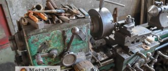
Classification of metal-cutting machines
A metal-cutting machine is used to grind workpieces to the dimensions and surface shapes specified by technological regulations.
Processing is carried out with a cutting or abrasive tool. All metalworking equipment is classified according to certain criteria, depending on the type of technological process, cutting tool, and machine layout.
An example of machine classification depending on the type of processing
The concept of processing accuracy.
It is impossible to produce a batch of interchangeable parts of absolutely the same size, since the accuracy of processing is affected by inaccuracy and wear of the machine, wear of the cutter, inaccuracies in installing and securing the workpiece and other reasons. As a rule, all parts of a given batch during processing have deviations from the specified sizes and shapes. But the magnitudes of these deviations must be assigned in such a way that the mating dimensions can ensure the assembly of parts without adjustment, i.e. so that the parts are interchangeable.
When assigning the value of permissible deviations to mating parts, product designers are guided by the standards established by the state - GOST. Below we briefly outline the basic concepts of tolerances and maximum deviations arising from GOST 7713-55 .
The concept of tolerance and maximum deviations. The amount of permissible deviations is indicated in the drawings of the part with plus and minus signs.
minus sign indicates that the part can be manufactured with a smaller deviation; plus sign indicates that the part can be manufactured with a larger deviation. For example, the size 10-0.1 mm shows that the block can be milled so that after processing its size lies between 10 mm and 9.9 mm. Likewise, the groove diameter of 10+0.2 mm shows that the groove can be milled so that after processing its size lies between 10 mm and 10.2 mm.
10 + 0.2-0.1 mm indicated in the drawing shows that the processed part will be suitable if its size is at least 9.9 mm and no more than 10.2 mm , i.e. lies within these limits.
The nominal size is the main calculated size from which deviations are assigned. If the drawing indicates a size of 10+0.2-0.1 mm , then the size of 10 mm is called nominal.
The actual size is the size obtained by measuring the machined part. The dimensions between which the actual size of a suitable part may lie are called limiting dimensions . The actual size of a part with dimensions 10+0.2-0.1 mm can lie in the range 10+0.2 = 10.02 mm and 10-0.1 = 9.9 mm . The larger size is called the largest limit size , and the smaller size is called the smallest limit size .
The difference between the largest and smallest limit sizes is called size tolerance .
- The upper limit deviation is the difference between the largest limit size and the nominal size.
- The lower limit deviation is the difference between the smallest limit size and the nominal size.
Tolerance can also be defined as the difference between the upper and lower limit deviations.
The actual deviation is the difference between the actual and nominal sizes.
When graphically depicting tolerances, dimensional deviations are plotted from a line corresponding to the nominal size and called the zero line; positive deviations are plotted upward from the zero line, and negative deviations are plotted downward.
Gaps and tightness.
If a block with side dimensions of 10-0.1 mm is placed in a groove with side dimensions of 10+0.2+0.1 mm , then there will be a gap in the connection of the block with the groove, and the block can be moved along the groove. This fit (the mating of two parts) is called free . The largest gap in this case will be 0.3 mm , and the smallest will be 0.1 mm .
If the size of the block is 10+0.2+0.1 mm , and the groove is 10-0.1 mm , then the block will not fit freely into the groove and will have to be inserted with force or pressed. The connection will have an interference or negative gap, the smallest value of which is 0.1 mm . And the largest is 0.3 mm . This type of landing is called stationary, since the block cannot be moved along the groove.
Thus, the following conclusions can be drawn.
- The gap is the positive difference between the size of the groove and the size of the bar, ensuring freedom of their movement relative to each other.
- The interference is the negative difference between the size of the groove and the size of the block (the size of the block is larger than the size of the groove), which, after the block is seated in the groove, creates a fixed connection between them.
Landings.
Fit is the nature of the connection of mating parts, determined by the difference between the dimensions of the groove and the bar, creating more or less freedom (gap or interference) of their relative movement or the degree of resistance to mutual movement. Depending on whether there is a gap or interference between the bar and the groove, fits with clearance, interference and transitional fits are distinguished.
Landings with clearance, or free , are those landings that provide the possibility of relative movement of mating parts during operation. Depending on the size of the gap, the degree of relative movement of parts connected by a free fit may be different. To rotate the spindle of a milling machine, the clearance in the bearings must be smaller and, therefore, the fit must be tighter than for fitting rings on a milling mandrel.
Interference fits, or fixed ones , are called fits in which during operation there should be no movement of the mating parts relative to each other. Depending on the amount of interference, the degree of freedom of the mating parts of a fixed fit may be different. Thus, the fit of the shaft journal into the ball bearing ring is carried out with less interference than the fit of a railway car wheel onto the axle journal.
With transitional fits, it is possible to obtain both interference and clearances. With the largest maximum size of the block and the smallest maximum size of the groove, an interference is obtained, and with the smallest maximum size of the block and the largest maximum size of the groove, a gap is obtained (in the tolerance tables in the “interference” column it is indicated by a minus sign).
Below are plantings related to the three groups considered; Their abbreviations are given in parentheses.
The greatest interference is obtained with a shrink fit , the least - with press fits ; the smallest gap is obtained with a sliding fit , a little larger with a motion landing , almost three times larger with a running fit , then even larger with a light-stroke fit and, finally, the largest with a wide-stroke fit .
With a tight , tight , tense and tight fit , as mentioned above, interference and gaps are possible depending on the resulting size deviations.
General classification
Metal processing equipment is divided into 11 groups:
- Metal lathes. External and internal surfaces of rotation are processed. They have one thing in common: rotation of the part around its axis.
- Drilling machines. This group also includes boring machines. Used for passing through and blind holes. They are united by the rotation of the working tool and its simultaneous feeding. In horizontal boring mechanisms, feeding occurs due to the movement of the work table with the fixed part.
- Grinding machines. All such machines use an abrasive grinding wheel as a working tool.
- Polishing and finishing machines. A common feature is the use of abrasive wheels and polishing pastes.
- Gear processing machines. Designed for cutting gear and wheel teeth. This also includes grinding machines.
- Milling machines. In this group, the working tool is a multi-edge milling cutter.
- Planing machines. For these machines, the working stroke is a reciprocating movement of the cutter or workpiece.
- Slitting machines. They are used for dividing into parts by cutting a metal profile (angle, channel, rod, etc.).
- Broaching machines. The working tools are special multi-blade broaches.
- Thread processing machines. This includes equipment specifically designed for thread cutting. This group does not include lathes.
- Auxiliary and miscellaneous machines. They belong to a separate group and perform various auxiliary operations.
Classification by type
Equipment of the same type may have different layouts. A milling machine can be called horizontal or vertical - based on the location of the spindle axis. Kinematic schemes for transmitting movements, control systems, and cutting accuracy parameters differ.
Machines of the same type with a similar layout and kinematics, but having different sizes, will be combined into a size range. For example, gear hobbing machines are divided into 12 standard sizes depending on the parts being manufactured (from 80 mm to 12,000 mm). Each standard size of a machine designed for a specific processing of parts is called a model. Each model has its own designations: a combination of numbers and letters indicating the machine group, the maximum dimensions of the workpiece, the difference from the base model.
Classification by versatility
Processing mechanisms of the same group can perform different tasks:
- Universal ones process a wide range of products. The dimensions of the blanks may vary. Capable of performing any technological operations provided for this group.
- Specialized ones produce parts of the same type (body parts, shafts, similar in shape, but different in size).
- Special ones perform operations on one part of various sizes.
Classification by degree of accuracy
The degree of processing accuracy on a given machine is indicated by the letter included in its designation:
- N - normal accuracy;
- P - increased accuracy;
- B - high accuracy;
- A - particularly high accuracy;
- C - especially precise master machines.
Example: 16K20P - a lathe with increased accuracy.
Classification by degree of automation
Processing equipment is divided into automatic and semi-automatic. The working cycle of the machines is completely autonomous. In semi-automatic machines, loading of workpieces and removal of processed products is carried out by the operator. It also launches the next processing cycle.
Integrated automation of large-scale production of metal products involves the installation of automatic production lines from separate automatic machines. Products are produced in small batches using flexible production modules.
Machines that produce products under CNC control are designated by the letter C (cycle) or F. The numbers indicate a feature of the control system:
- F1 - digital display and preliminary selection of coordinates;
- F2 - positional control system;
- F3 - loop control system;
- F4 is a universal control system.
For example, the range of CNC metal lathes from the StankoMashKompleks company can be viewed at the link provided.
Classification by weight
Depending on the mass of manufactured parts, machines are divided into:
- lightweight, weighing up to 1000 kg;
- medium, weighing up to 10,000 kg;
- heavy, weighing from 10,000 kg, which, in turn, are divided into large (16,000-30,000 kg) and actually heavy (up to 100,000 kg);
- especially heavy - over 100,000 kg.
Machine numbering
Identification of any metalworking machine is based on assigning an alphanumeric code to it.
The numbers indicate which group the machine belongs to (lathe, milling, etc.), indicate the type and nominal size of the equipment. By deciphering the numbering, you can find out the height of the centers, the maximum dimensions of the workpieces or the drilling diameters of the workpieces.
Machining machines of the same size but with different characteristics are identified by the letter entered between the first and second digit. For example, lathes models 162 and 1K62 differ in maximum rotation speed. The first one has 600 rpm, the second one has 2000 rpm.
The difference between modifications of machines of the same model can be determined by the letter at the end of the number. If the numbering of the basic model of a horizontal milling machine is 6N82, then the simplified modification of this machine is 6N82G.
Numbering occurs when the fourth digit identifies an improved version of a machine of the same standard size. Thus, the horizontal boring machine model 262 has a modern modification, designated 2620.
Assigning alphanumeric indices to metalworking machines makes it easy to find the corresponding equipment in special catalogs. Indexing also makes it possible to quickly find the necessary spare parts.
Accuracy classes.
Manufacturing accuracy is characterized by the amount of permissible deviations from the specified dimensions and shape. Different machines require parts with different processing precision. It is obvious that parts of a plow, road roller and other agricultural and road machines can be manufactured less accurately than parts of a milling machine, and parts of a milling machine require less precision than parts of a measuring instrument. In this regard, in mechanical engineering, parts of different machines are manufactured according to different accuracy classes. Ten accuracy classes (were) adopted in the USSR.
- five of them: 1st, 2nd, 2a, 3rd, Za - require the greatest processing accuracy;
- two others: 4th and 5th - smaller;
- the other three: 7th, 8th, 9th - even smaller.
Application of accuracy classes in various fields
- 1st class of accuracy is used in the manufacture of particularly precise products. Due to very small tolerances, work in the 1st class of accuracy requires highly qualified workers and precision equipment, fixtures and tools.
- Accuracy classes 2 and 2a are used most often. They are used to manufacture critical parts of machine tools, automobile, tractor, aircraft and electric engines, textile and other machines. Along with this, in the mechanical engineering industries that produce these machines, parts of less critical connections are manufactured using the 3rd, 4th, 5th and other coarser accuracy classes.
- 3rd and 3rd accuracy classes are used mainly in heavy mechanical engineering in the production of turbines, steam engines, internal combustion engines, transmission parts, etc.
- According to the 4th accuracy class, parts of agricultural machines, steam locomotives, railway cars, etc. are manufactured.
- The 5th accuracy class is used in mechanical engineering for non-critical parts of less precise mechanisms.
- The 7th, 8th and 9th accuracy classes are used in the manufacture of coarser parts and especially during procurement operations: casting, stamping, coppersmithing, etc.
- Free dimensions of parts are usually carried out according to the 5th or 7th accuracy classes.
To show with what fit and to what accuracy class the part needs to be manufactured, a letter indicating the fit and a number corresponding to the accuracy class are placed in the drawings on the nominal mating dimensions. For example, C4 means: sliding landing of the 4th accuracy class ; X3 - running landing of the 3rd accuracy class , etc. For landings of the 2nd accuracy class (especially widespread) the number 2 is not used . Therefore, if in the drawing there is no number next to the fit letter on the mating size, this means that the part must be manufactured according to the 2nd accuracy class. For example, L means easy landing of the 2nd accuracy class.
Classification of metal-cutting machines - all about equipment for metal processing
Metal-cutting machines produced by domestic manufacturers are divided into several categories, which are characterized by the corresponding classification. You can determine which category this or that equipment belongs to by its labeling, which says a lot to those who understand it. However, no matter what category the metal-cutting device belongs to, the essence of processing on it comes down to the fact that the cutting tool and the part perform form-building movements, and it is they that determine the configuration and dimensions of the finished product.
The most common types of metal-cutting machines: 1-6 - lathes, 7-10 - drilling, 11-14 - milling, 15-17 - planing, 18-19 - broaching, 20-24 - grinding.
Types of metal-cutting equipment
Depending on their purpose, metal-cutting machines are divided into nine main groups. These include the following devices:
- lathes - all types of lathe machines (in the marking they are indicated by the number “1”);
- drilling and boring - machines for performing drilling operations and boring (group “2”);
- grinding, polishing, finishing - metal-cutting machines for performing finishing, grinding, sharpening and polishing technological operations (group “3”);
- combined - metal-cutting devices for special purposes (group “4”);
- thread and gear processing - machines for processing elements of threaded and gear connections (group “5”);
- milling - machines for performing milling work (group “6”);
- slotting, planing and broaching - metal-cutting machines of various modifications, respectively, for planing, slotting and broaching (group “7”);
- cutting - equipment for performing cutting work, including saws (group “8”);
- different - examples of such metal-cutting units are centerless-grinding, saw-cutting and others (group “9”).
Grinding machines
GOST 14-88. Surface grinding machines with a round table and a horizontal spindle
This standard applies to surface grinding machines with a round table with a diameter of up to 1250 mm and a universal-purpose horizontal spindle of accuracy classes B and A, manufactured for the needs of the national economy and export. The requirements of this standard are mandatory
GOST 27-88. Surface grinding machines with a round extendable table and a vertical spindle
This standard applies to surface grinding machines with a round pull-out table and a vertical spindle for universal purposes, accuracy classes P and V with a table diameter of up to 1600 mm, manufactured for the needs of the national economy and export
GOST 273-90. Surface grinding machines with cross table and horizontal spindle
This standard applies to surface grinding machines with a cross table and a horizontal spindle for general purpose, accuracy classes B, A and C, manufactured for the needs of the national economy and export. The standard establishes the basic dimensions and accuracy standards of surface grinding machines with a cross table and a horizontal spindle, ensures interchangeability and technical compatibility
GOST 6728-91. Thread grinding machines
This standard applies to universal thread grinding machines, including thread grinding machines for lead screws, manufactured for the needs of the national economy and export
GOST 13135-90. Surface grinding machines with a rectangular table.
This standard applies to surface grinding machines with a rectangular table and a horizontal spindle of accuracy classes B and A with a table width of up to 1000 mm, to surface grinding machines with a rectangular table and a vertical spindle of accuracy class B with a table width of up to 1000 mm and to two-column longitudinal grinding machines for guide classes precision B and A with a table width of up to 3150 mm, manufactured for the needs of the national economy and export
GOST 9735-87. Profile grinding machines
This standard applies to profile grinding machines with an optical device, general purpose, including CNC, accuracy classes P*, B and A
Machine markings
The classification of equipment intended for processing metal workpieces assumes that, having seen its markings, any specialist will immediately be able to tell which metal-cutting machine is in front of him. This marking contains alphabetic and numerical symbols that indicate individual characteristics of the device.
The first number is the group to which the metal-cutting machine belongs, the second is the type of device, its type, the third (and in some cases the fourth) is the main standard size of the unit.
Decoding the markings of metal-cutting machines
After the numbers listed in the model marking, there may be letters that determine whether the model of the metal-cutting machine has special characteristics. These characteristics of the device may include its level of accuracy or indication of modification. Often in the designation of a machine, the letter can be found after the first digit: this indicates that this is a modernized model, in the standard design of which some changes have been made.
As an example, you can decipher the markings of the 6M13P machine. The numbers in this designation indicate that we have a milling machine (“6”) of the first type (“1”), which belongs to the 3rd standard size (“3”) and allows processing with increased accuracy (letter “P” ). The letter “M” present in the marking of this device indicates that it has been modernized.
Automation levels
Types of lathes, as well as devices for any other purpose that are used in mass and large-scale production, are called aggregate. They received this name due to the fact that they are assembled from the same type of units (units): beds, working heads, tables, spindle units and other mechanisms. Completely different principles are used when creating machines that are necessary for small-scale and single-piece production. The design of such devices, which are highly versatile, can be completely unique.
CNC lathe
Classification of lathes (as well as equipment of any other categories) according to the level of automation implies their division into the following types:
- manual models, all operations on which are carried out manually;
- semi-automatic, in which part of the technological operations (installation of the workpiece, starting the device, removing the finished part) is performed manually (all other auxiliary operations are carried out in automatic mode);
- automatic, for which you only need to set processing parameters; they perform all other operations independently, in accordance with a given program;
- metal-cutting units with CNC (all processes on such machines are controlled by a special program that contains a coded system of numerical values);
- metal-cutting equipment belonging to the category of flexible automated modules.
The most prominent representatives of metal-cutting machines are CNC devices, the operation of which is controlled by a special computer program. Such a program, which is entered into the machine’s memory by its operator, determines almost all parameters of the unit’s operation: spindle speed, processing speed, etc.
Even the most compact desktop machines can be equipped with a CNC system
All types of metalworking machines equipped with a CNC system contain the following standard elements in their design.
- The operator's console (or console), through which a computer program that controls its operation is stored in the machine's memory. In addition, using such a remote control, you can manually control all parameters of the unit’s operation.
- The controller is an important element of the CNC system, with the help of which not only control commands are generated, transmitted to the working elements of the equipment, and the correctness of their execution is monitored, but also all the necessary calculations are made. Depending on the degree of complexity of the unit model, either a powerful compressor or a conventional microprocessor can be used as a controller to equip it.
- A screen or display that acts as a control and control panel for the operator. This element allows you to monitor the operation of a metal-cutting machine in real time, control the processing process, and, if necessary, quickly change parameters and settings.
The operating principle of metalworking machines equipped with a CNC system is simple. A program is first written that takes into account all the requirements for processing a specific workpiece, then the operator enters it into the machine controller using a special programmer. The commands embedded in such a program are sent to the working elements of the equipment, and after they are executed, the machine automatically turns off.
The use of metal-cutting machines equipped with numerical control allows processing with high accuracy and productivity, which is the reason for their active use to equip industrial enterprises that produce products in large series. Due to their high level of automation, such units are perfectly integrated into large automated lines.
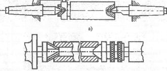
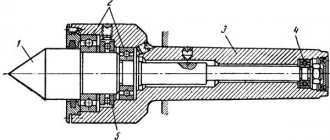
The device of a screw-cutting lathe
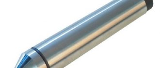
PRECISION OF PROCESSING SAMPLES-PRODUCTS
2.1. For inspections, hardened steel product samples are used, with a hardness of 41.5 ... 51.5 HRCe, the shapes and dimensions of which are given in the drawing. 26, 30 and 31 and in table. 16 and 21 and which meet the requirements of GOST 25443-82.
2.2. Before installing sample products on the machine, their base surfaces, which are used for installation and fastening on the machine, are finished polished, and the surfaces to be checked are pre-grinded. In this case, the roughness of the base surfaces should be no rougher than Ra
1.25 according to GOST 2789-73, and surfaces subject to subsequent finishing and inspection should be no rougher than
Ra
2.5 according to GOST 2789-73.
2.3. The surfaces of the product samples to be checked are processed using finishing modes. After finishing grinding, the permissible deviations of the surfaces being tested should not exceed the values specified in paragraphs. 2.6 - 2.8 and 2.10 - 2.13.
2.4. The shape and dimensions of the sample product for all machines for checks 2.5 - 2.8 and 2.13 must correspond to the drawings. 26 and table. 16.
Crap. 26
Table 16
mm
| Maximum length of processed surface | Sample-product exchanges (maximum deviations ± 5) | ||
| l | b | h | |
| Up to 160 | 65 | 30 | 40 |
| St. 160 to 250 | 100 | 50 | 65 |
| » 250 » 400 | 160 | 50 | 65 |
| » 400 » 630 | 250 | 50 | 65 |
2.5. Flatness of machined surface B
(drawings 26 and 27).
Crap. 27
Table 17
| Maximum length of the processed surface, mm | Tolerance, microns, for precision class machines | ||
| P | IN | A | |
| Up to 160 | 6 | 4 | 2,5 |
| St. 160 to 250 | 8 | 5 | — |
| » 250 » 400 | 10 | 6 | — |
| » 400 » 630 | 12 | 8 | — |
The check is carried out using a device consisting of a calibration plate 3
and measuring device
2.
Sample product
1
is placed with the surface being tested on plate
3
and moved along it in a reciprocating motion. The deviation is equal to the largest algebraic difference in the readings of the measuring device.
2.6. Constancy of linear dimensions in sections parallel to the base G
sample product
(Fig. 26).
Table 18
| Maximum length of the processed surface, mm | Tolerance, microns, for precision class machines | ||
| P | IN | A | |
| Up to 160 | 10 | 6 | 4 |
| St. 160 to 250 | 12 | 8 | — |
| » 250 » 400 | 16 | 10 | — |
| » 400 » 630 | 20 | 12 | — |
The test is carried out in three sections in height, parallel to the base G
sample product: in the middle of the height and at a distance of approximately 5 mm from the top and bottom edges.
The check is carried out with a device for measuring linear dimensions.
The deviation is equal to the largest difference in the instrument readings.
2.7. Perpendicularity of vertical processed surfaces A, B
and
At
the base
D
of the product sample
(Fig. 26 and 28).
Crap. 28
Table 19
| Maximum length of the processed surface, mm | Tolerance, microns, for precision class machines | ||
| P | IN | A | |
| Up to 160 | 8 | 5 | 3 |
| St. 160 | 10 | 6 | — |
Measurements - according to GOST 25889.3-83, method 2.
The sample product is installed with base G
for adaptation.
2.8. Perpendicularity of processed surfaces A
to
B
and
B
to
B
(drawings 26 and 29).
Crap. 29
Table 20
| Maximum length of the processed surface, mm | Measurement length b 1, mm | Tolerance µm, for precision class machines | ||
| P | IN | A | ||
| Up to 160 | 25 | 20 | 12 | 8 |
| St. 160 | 45 | 25 | 16 | — |
Measurement - according to GOST 25889.3-83, method 2.
The sample product is mounted on the fixture with surface B.
2.9. The shapes and dimensions of the shaped sample product (for CNC machines) for checks 2.10 and 2.11 must correspond to the drawings. 30 and table. 21.
Crap. thirty
Table 21
| Maximum length of the processed surface, mm | l | b | a | h | R | α | β |
| mm | |||||||
| Up to 250 | 100 | 65 | 25 | 5 | 8 | 40° | 50° |
| St. 250 to 630 | 160 | 100 | 35 | 10 | |||
2.10. Accuracy of linear and angular dimensions of a shaped sample product (for CNC machines)
Tolerance for machines of accuracy class:
P
size R
………………………………… 15 µm
angles a, b…………………………….. 3′
IN
size R
………………………………… 10 µm
angles a, b…………………………….. 2′
2.11. Straightness of surfaces A
and
B
shaped sample product
(for CNC machines)
Table 22
| Maximum length of the processed surface, mm | Tolerance, microns, for precision class machines | |
| P | IN | |
| Up to 250 | 16 | 10 |
| St. 250 to 630 | 25 | 20 |
2.12. Accuracy of linear dimensions of the sample product
(for CNC machines)
*Size for reference.
Crap. 31
Tolerances, microns, of all dimensions indicated on the drawing should be for machines of the accuracy class:
P…………………………………………± 16
B…………………………………………± 10
A…………………………………………± 6
Unspecified maximum dimensional deviations: H14, h14,±
Measurements are carried out using a device for measuring linear dimensions.
2.13. Roughness of treated surfaces according to
GOST 2789-73
(drawings 26, 30, 31).
Roughness parameter Ra,
µm, no more, for machines of accuracy class:
P…………………………………………………………… 0.63
B……………………………………………………… 0.40
A…………………………………………………………… 0.25
The test is carried out using surface roughness control tools.
General classification
The classification of metal-cutting machines is carried out according to various factors. These are divisions by weight, dimensions, type, accuracy class, degree of automation, and versatility. We need to talk about each of their groups in more detail.
Classification by type
There are 9 types of installations based on the type of equipment:
- Lathes. They occupy approximately 30% of the total mass of metal-cutting devices. The workpiece is clamped in a special clamp. The cutting process begins after installing the cutters, which remove a layer of metal under the influence of rotation.
- Boring, drilling units. They occupy 20% of the total mass of machines. The parts are fixed on the work table. Cutting occurs due to the rotation of the spindle with a drill clamped in the chuck.
- Grinding, grinding, polishing machines. They occupy 20% of the total mass of metal cutting installations. Metal cutting occurs due to the rotation of the abrasive material, which comes into contact with the working surface. The processing speed depends on the size of the abrasive.
- Devices for physical and chemical cutting of workpieces. Least common equipment.
- Devices for processing threads and teeth. Occupies 6% of the mass. Used for threading, manufacturing, and sharpening gears.
- Slotting, broaching, planing machines. They occupy 4% of the mass of metal-cutting equipment.
- Milling machines. They occupy 15% of the total mass. Processing of metal workpieces occurs due to the rotation of cutters of different shapes.
- Split installations. Used to separate reinforcement, profiles, corners.
- Machines for performing various operations related to cutting.
Classification by versatility
A separate division of metal-cutting machines is based on their versatility. There are two groups:
- Narrow profile installations. Used to perform one specific technological operation.
- Universal units. They are large-sized structures that are designed to perform various technological operations.
For better performance of technological operations, it is better to buy several machines with a narrow profile.
Classification by degree of accuracy
In terms of accuracy, metal-cutting machines come in several types, each of which has its own marking:
- Increased - denoted by the letter P.
- Normal - designation N.
- High - indicated by the letter B.
- Particularly high - designation A.
- The highest accuracy is indicated by the letter C.
To use units marked B, A, C, you need to prepare the room in advance. It must maintain a constant temperature and humidity level.
Classification by degree of automation
Based on the degree of automation, the following types of metal-cutting machines are distinguished:
- Manual models. The worker needs to clean, prepare workpieces, set up all moving elements independently, and coordinate the work process.
- Semi-automatic machines. The worker needs to change parts independently, turn on and off moving mechanisms.
- Automatic machines are units that process workpieces independently. Used in mass production.
- CNC equipment. The operator sets the required algorithm through the program. The moving mechanisms work independently, select optimal modes, load and unload parts.
CNC machines are gradually replacing other machines due to high processing accuracy and increased productivity.
Metal cutting automatic machine
Classification by weight
Industrial metal-cutting machines are divided by weight. Highlight:
- Lightweight - structures weigh up to 1000 kg.
- Medium - weight starts from 1 ton and ends at 10 tons.
- Large - weight from 16 to 30 tons.
- Heavy - weight from 30 to 100 tons.
- Super heavy - structures weigh more than 100 tons.
Designations are indicated in the technical data sheet.
Machine markings
Short designations consisting of letters and numbers indicate different technical characteristics, purpose, and manufacturer of the units. Markings are divided into two groups:
- Marking of serial production machines. The first digit indicates the group, the second the type. The letter after the first two digits indicates a modernization of the design. Next, the operational parameter is indicated by two numbers. After it, the CNC type is indicated in one letter with a number. The last letter with a number designates the CNC computing device.
- Marking of specialized installations. The first two letters indicate the abbreviated name of the manufacturer. After it, the main operational parameter is indicated in three digits. The modification is further indicated by a letter. The last letter and number indicate the CNC computing device.
After such markings, separate symbols may be added that indicate technical characteristics. A more accurate decoding can be found in the tables available on the Internet.
Automation levels
Manual installations are giving way to CNC equipment. This automation system consists of several interconnected elements:
- Remote Control.
- Monitor for task of algorithms, control of work process.
- Sensors that determine the position of the workpiece on the work table and the movement of the equipment.
- Stepper motors that are controlled by a computer.
The operator must have practical experience in setting up and repairing such systems.
CNC metal cutting machine
Numbers after the decimal point
The number of digits after the decimal point directly depends on what type of motors are installed on the CNC machine.
If stepper motors are installed, the working field will have immediate dimensions of 600 × 900 mm.
Machines equipped with servomotors are distinguished by the presence of 3 to 5 zeros after the decimal point. Most often, these parameters correspond to precision metalworking machines.
IMPORTANT! The more decimal places a CNC machine can process, the higher its accuracy.
Machine design
Almost all equipment that is used to work with metal parts is similar in design. There are two large groups based on the movement of working parts:
- Supply of equipment to the workpiece.
- Feeding the part to the cutting parts of the installation.
There are elements that are typical for any metal-cutting machines:
- Control system.
- A bed onto which other parts are attached.
- Desktop.
- Electric motor with the ability to install equipment and secure workpieces.
Other elements may vary depending on the type of equipment.
Selection principles
When choosing a metal cutting machine, you need to consider some factors:
- Control system.
- Dimensions, installation weight.
- Ability to perform one or more technological operations.
Advantages and disadvantages
Metal-cutting equipment has a number of strengths and weaknesses. Advantages:
- Automation of the work process with CNC.
- High precision metal processing.
- High performance.
- Reliability, durability.
- The need to install a cooling system.
- Difficulties in repair.
- Experience in CNC setup.
It is important to carefully monitor the work process to reduce the risk of injury or part rejection.
Metal cutting precision
Manufacturers and cost
Among the manufacturers of metal-cutting machines there are:
- Caliber - Russia.
- Energomash - Russia.
- Jet - Russia.
The price depends on the type, size, performance, availability of additional functions, control system. The cost of standard industrial metal-cutting equipment starts from 500,000 rubles.
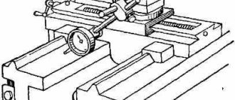
How to properly check a lathe
The quality of the test largely depends on how correctly the equipment is installed on the test bench. The machine must be installed strictly following the drawing. The most popular and reliable way is to install the unit on several supports (more than three). All moving components and elements must be installed in the middle position.
The quality of manufactured products depends on the geometric accuracy of the equipment. Therefore, the workpiece must be installed on a geometrically correct surface.
To determine the degree of wear, a ruler is installed in turn on each guide of the machine. Then, using a feeler gauge, you need to measure the gap between the ruler and the guide. GOST defines the maximum permissible value of this gap - no more than 0.02 mm. With a larger deviation, the processed parts may have an unacceptable output error.
Accuracy largely depends on the horizontality of the machine guides. This indicator is measured using a special level. The maximum deviation should be no more than 0.05 mm.
When checking the equipment for serviceability, pay attention to all rotating parts. Their movement must be carried out strictly along the axis; beating during rotation is unacceptable
If any element deviates from the axis of rotation, this not only affects the quality of the manufactured products, but also threatens the safety of the operator. When the workpiece “beats” in the machine, there is a risk of injury due to a part flying out of the holders or a broken tool.
When checking equipment, it is also important to determine the accuracy of the propeller pitch. To determine the error and deviation there is a special technique: Read also: DIY garage tables
Read also: DIY garage tables
a mandrel is installed in the headstock of the machine;
a cylindrical nut with a groove is fixed onto it;
a holder with an indicator is fixed into the groove of the nut, which should rest against the end of the nut;
the device must be configured for a threaded pitch;
During operation, the indicator records the error.
Exploitation
To safely operate a metal-cutting machine, you need to follow safety rules and take into account some features:
- Work using protective equipment, glasses, headphones, gloves.
- Check the integrity of the equipment (drills, cutters, cutters, abrasives) before starting the installation.
- Cool the work area. Water or oil can be used for this.
- Clean the structure from metal shavings after work.
- Lubricate moving parts at least 2 times a month.
Classification of lathes
According to the classification of machine tools adopted in the USSR, all metal-cutting machines are divided into the following groups: 1 - turning; 2 - drilling and boring; 3 - grinding, polishing, finishing; 4 - combined; 5 - gear processing; 6 - milling; 7 - planing, slotting and broaching; 8—split; 9 - different. Groups are divided into types, and types are divided according to the size of the machines or the size of the workpieces processed.
Group 1. Turning
1 — Automatic and semi-automatic single-spindle
2 — Automatic and semi-automatic multi-spindle
6 — Turning and frontal
Classification and designation system of metal-cutting machines
Metal-cutting machines, depending on the type of processing, are divided into nine groups, and each group into ten types (subgroups), characterizing the purpose of the machines, their layout, the degree of automation or the type of tool used. For example, group 4 is intended for electroerosive, ultrasonic and other machines.
The machine model designation consists of a combination of three or four numbers and letters. The first digit means the group number, the second - the subgroup number (machine type), and the last one or two digits - the most characteristic technological parameters of the machine.
For example:
1E116
— means a single-spindle turret lathe with the largest diameter of the processed bar being 16 mm;
2Н125
- means a vertical drilling machine with the largest nominal drilling diameter of 25 mm;
2G103P
is a high-precision desktop vertical drilling machine with the largest nominal drilling diameter of 3 mm.
The letter after the first digit indicates different versions and modernization of the main basic model of the machine. The letter at the end of the digital part means a modification of the base model, the accuracy class of the machine or its features.
Machine accuracy classes mean:
N
- normal;
P
- increased, accuracy 0.6 deviations from N;
B
– high, accuracy 0.4 deviations from H;
A
- especially high accuracy, accuracy 0.25 deviations from H;
C
- especially precise machines, accuracy 0.16 deviations from N.
P, V, A, S
— precision machines (high accuracy).
The following indexing of models of computer-controlled machine tools is accepted:
C
— with cyclic control;
F1
- with digital position indexing, as well as with a preliminary set of coordinates;
F2
- with a CNC positional system,
FZ
- with a CNC contour system;
F4
- with a combined CNC system.
For example:
16D20P
— high-precision screw-cutting lathe;
6Р13К-1
- vertical milling console machine with a copying device;
1G340PTs
- turret lathe with a horizontal head, increased accuracy, with cyclic program control;
2455AF1
- coordinate-boring two-column machine of particularly high accuracy with a preliminary set of coordinates and digital display;
2R135F2
- vertical drilling machine with a turret head, a cross table and a positional numerical control system;
16K20FZ
- lathe with a contour numerical control system;
2202VMF4
is a multi-purpose (drilling-milling-boring) horizontal high-precision machine with a tool magazine and a combined CNC system (the letter M means that the machine has a tool magazine).
Machines are divided into universal (general purpose), widely universal (limited number of operations), specialized (one name), special and aggregate (made up of interchangeable units).
Special and specialized machines are designated by a letter index (of one or two letters) assigned to each plant, with the model number of the machine. For example, mod. MSh-245 is a semi-automatic rack grinder with increased precision produced by the Moscow Grinding Machine Plant.
Based on weight, machines are divided into the following categories:
before 1
t - light;
up to 10
t - average;
up to 30
t - large;
up to 100
t - heavy;
St. 100
t is unique.
at the same time, up to 5
tons are transportable;
St. 5
t - not transportable.
By degree of automation:
with manual
— worker commands are needed;
semi-automatic
- only for adjustment, installation and removal of workpieces;
automatic
- without the participation of a worker from installing a
CNC
- semi-automatic or automatic, controlled according to a pre-compiled and easily replaceable program.
CLASSIFICATION OF METAL-CUTTING MACHINES
| Machine tools | Group | Machine type | Purpose of the machine |
| LATHE | 1 | 0 | specialized automatic and semi-automatic machines |
| 1 | single-spindle automatic and semi-automatic machines | ||
| 2 | multi-spindle automatic and semi-automatic machines | ||
| 3 | turning-turret | ||
| 4 | semi-automatic turning-turret | ||
| 5 | carousel | ||
| 6 | turning and loboturning | ||
| 7 | multi-cutting and copying | ||
| 8 | specialized | ||
| 9 | different lathes | ||
| DRILLING AND BORING | 2 | 0 | — |
| 1 | benchtop and vertical drilling | ||
| 2 | semi-automatic single-spindle | ||
| 3 | semi-automatic multi-spindle | ||
| 4 | jig boring | ||
| 5 | radial and coordinate drilling | ||
| 6 | boring | ||
| 7 | finishing and boring | ||
| 8 | horizontal drilling | ||
| 9 | different drilling | ||
| GRINDING, POLISHING, FINISHING, SHARPENING | 3 | 0 | — |
| 1 | cylindrical grinding, centerless grinding | ||
| 2 | internal grinding, coordinate grinding | ||
| 3 | roughing and grinding | ||
| 4 | specialized grinding machines | ||
| 5 | longitudinal grinding | ||
| 6 | sharpening | ||
| 7 | flat grinding | ||
| 8 | lapping, polishing, honing, finishing | ||
| 9 | various machines working with abrasives | ||
| ELECTROPHYSICAL, ELECTROCHEMICAL | 4 | 0 | — |
| 1 | — | ||
| 2 | light beam | ||
| 3 | — | ||
| 4 | electrochemical | ||
| 5 | — | ||
| 6 | — | ||
| 7 | electroerosive, ultrasonic piercing | ||
| 8 | anodic-mechanical cutting | ||
| 9 | — | ||
| GOOTH and THREAD MACHINING | 5 | 0 | thread-cutting |
| 1 | gear shaping machines for cylindrical wheels | ||
| 2 | gear cutters for bevel wheels | ||
| 3 | Gear hobbing machines for cylindrical wheels and splined shafts | ||
| 4 | for cutting worm wheels | ||
| 5 | for machining the ends of wheel teeth | ||
| 6 | thread-milling | ||
| 7 | gear finishing, checking and rolling | ||
| 8 | gear and thread grinding machines | ||
| 9 | various gear and thread machining tools | ||
| MILLING | 6 | 0 | drum-milling |
| 1 | vertical milling console | ||
| 2 | continuous milling machines | ||
| 3 | longitudinal single-post | ||
| 4 | copying and engraving machines | ||
| 5 | vertical milling non-cantilever | ||
| 6 | longitudinal two-post | ||
| 7 | console-milling operating rooms | ||
| 8 | horizontal milling console | ||
| 9 | different milling | ||
| PLANING, SLOTTING, broaching | 7 | 0 | — |
| 1 | longitudinal single-post | ||
| 2 | longitudinal two-post | ||
| 3 | cross-planing | ||
| 4 | slotting | ||
| 5 | lingering horizontal | ||
| 6 | broaching vertical for pulling internal | ||
| 7 | broaching vertical for pulling outer | ||
| 8 | — | ||
| 9 | various planing machines | ||
| CUTTING | 8 | 0 | — |
| 1 | cutting, working with a cutter | ||
| 2 | cutting-off machines working with an abrasive wheel | ||
| 3 | smooth or grooved disc | ||
| 4 | correct-cutting | ||
| 5 | band saws | ||
| 6 | cutting-off with circular saw | ||
| 7 | cutting-off hacksaws | ||
| 8 | — | ||
| 9 | — | ||
| DIFFERENT | 9 | 0 | — |
| 1 | pipe and coupling processing | ||
| 2 | saw-cutters | ||
| 3 | straight- and centerless-grinding | ||
| 4 | — | ||
| 5 | for testing tools | ||
| 6 | dividing machines | ||
| 7 | balancing | ||
| 8 | — | ||
| 9 | — |
Code of turning machines
When designating the code for machines in a turning group, the first digit 1 indicates the group of machines. The second number indicates the type of lathe. The subsequent numbers, as a rule, show the technological parameter of the machine, namely: the maximum diameter of the workpiece, the height of the centers, etc. The letter after the first or second code can symbolize the generation of the machine, the manufacturer or modification. The letter placed at the end of the digital code may indicate an improvement in the base model or the accuracy class of the machine.
Here are some examples of the designation of lathe models.
1K62 - number 1 - group of lathes; 6 — turning and wine-cutting machine; 2 — height of centers, dm; letter K - generation.
1A616 - figure - group of lathes; 6 — screw-cutting lathe; 16 — height of centers, cm; A - generation.
1B811 - number 1 - group of lathes; 8 — turning and backing; 1 - technological parameter that determines the dimensions of the workpieces being processed; B - generation.
16K20P - number 1 - group of lathes; 6 — turning screw-cutting; 20 — height of centers, cm; K - generation; P - accuracy class - increased.
It should be noted that the sixth type of machines includes screw-cutting lathes, and the eighth type includes backing lathes. In the machine tool industry, the majority of manufactured metal-cutting machines, including lathes, are manufactured according to state standards; in which the main parameters correspond to normal or size ranges. By dimensional or normal series we mean a group of similar machines, consisting mainly of standardized units and parts, each of which is designed for processing parts of certain sizes,
The size ranges (standard sizes) of universal screw-cutting lathes and two-column rotary lathes are given in table. 1.
The table shows that the main parameter that determines the standard sizes of machines is the dimensions of the installed part. Moreover, each subsequent standard size of the machine makes it possible to process a part with a diameter 1.26 times larger than that of the previous part. Thus, for universal screw-cutting lathes and rotary machines, the denominator of the size range is set to 1.26. In other words, the series of numbers is 250; 320; 400; 500; 630; 800; 1000 (2300; 3200; 4000; 5000; 6300; 8000) form a geometric progression with a denominator of 1.26.
The maximum height of the installed part on rotary machines also changes according to the law of geometric progression with a denominator equal to 1.26: 2000, 2500, 3200. The presence of two naturally changing main parameters: the largest diameter of the installed part and its heights makes it possible to also regularly change other technical characteristics machine: power of the main drive, weight of the installed part, etc.
According to the degree of specialization, all machines are divided into universal, specialized and special.
Universal machines are machines that can perform various operations on a wide range of parts.
Specialized are machines that can perform a limited number of operations on parts of the same type.
Special machines are machines designed to perform a limited number of operations on parts of one standard size.
Classification of lathes according to main and auxiliary characteristics
Turning (turning) is intended for the mechanical formation of the geometry of mechanical engineering parts with a blade tool by removing chips. The cutting kinematics is determined mainly by the relative rotational movement of the workpiece with a spatially fixed axis of rotation and an arbitrary feed movement. The objects of processing are most often coaxial surfaces of rotation and flat surfaces of parts such as shafts, disks and bushings, including cutting external and internal threaded surfaces, as well as surfaces of some other shapes, such as non-circular ones, by introducing additional relative movement of the tool [36]. The shapes of surfaces obtained by turning methods are given in table. 1.12.1.
Classification of machines of the turning group only by technological characteristics is insufficient due to the new capabilities provided by CNC devices in technological and design terms, therefore it is advisable to use characteristics that reflect the design and specific features of lathes, namely: the main design feature; auxiliary species character; layout; number of positions for securing workpieces; number of installed tools; type of management; accuracy class [20].
The classification of machines according to main and auxiliary characteristics is given in table. 1.12.2.
The layout of the machines is determined by the position of the main axis of rotation of the workpiece and the relative position of the tool in the spatial coordinate system used in ISO recommendation R-841. Based on this feature, horizontal and vertical layouts are distinguished.
The level of concentration of operations performed on one machine is characterized by the number of working positions and the method of securing workpieces (single- and multi-spindle cartridge; single- and multi-spindle collet (bar); single- and multi-spindle center; combined), as well as the conditions that determine the effectiveness of the tool used : the number and complexity of the shapes of the processed surfaces with different feed directions; number of different types of instruments; possibilities of spatial orientation of tools relative to the workpiece; comparability of surface treatment times.
Based on the number of positions for securing workpieces, single- or multi-spindle designs are distinguished, and based on the number of tools installed, machines are single- or multi-seat, multi-tooled and with a tool magazine.
In this regard, special attention is paid to the concentration of turning operations, the creation of multi-purpose lathes that combine off-center drilling, some milling and other similar operations. At the same time, measures are taken to reduce off-cycle losses associated with readjustment, control, loading and unloading, tool changing and others, which is possible with a developed CNC-based machine control system [4].
1.12.1. Typical surfaces obtained by turning
- External round cylindrical surface shape
- External longitudinal cylindrical turning: the axis of rotation of the workpiece and the feed line are parallel;
- External transverse round turning: the axis of rotation of the workpiece and the feed line are mutually perpendicular;
- External centerless turning: longitudinal cylindrical turning with several rotating tools with a small auxiliary entering angle at high feed rates
- Internal longitudinal circular boring: the workpiece rotation axis and the feed line are parallel;
- Internal longitudinal drilling (countersinking, reaming): the axis of rotation of the workpiece and the axis of the tool coincide;
- Internal transverse circular boring of a groove: the axis of rotation of the workpiece and feed are mutually perpendicular in a certain area
- External (internal) round double-sided turning with arbitrary feed using a combination of methods 1.1, 1.2 and 2.1, 2.3
- External longitudinal turning with displacement of one of the machine centers;
- External longitudinal turning with rotation of tool guides;
- External longitudinal turning with guide ruler;
- External cross turning with a tool with a wide inclined cutting edge
- Internal longitudinal boring is similar to methods 4.2, 4.3, transverse boring - to method 4.4
- External longitudinal helical turning with a single-tooth tool with a feed equal to the pitch and a cutting edge profile corresponding to the thread profile;
- The same, with a multi-toothed tool (threaded comb);
- The same, with a multi-toothed enclosing tool (die);
- External longitudinal cutting with multi-tooth rotating tool;
- External longitudinal female milling with multi-tooth tools;
- External longitudinal screw turning with an arbitrary pitch equal to the feed, according to method 4.1;
- External transverse screw turning of end spirals with an arbitrary pitch equal to the feed and thread profile according to method 16;
- External longitudinal external milling with multi-flute tool
- Internal longitudinal cutting with a single-tooth tool, the profile of the cutting edge of which corresponds to the profile of the thread root;
- Internal longitudinal cutting with a multi-toothed tool (tap) coaxial to the axis of rotation of the workpiece with a feed equal to the thread pitch of the tap
- External transverse undercutting feed direction is perpendicular to the axis of rotation of the workpiece;
- External longitudinal undercut turning; the main cutting edge of the tool is perpendicular to the axis of rotation of the workpiece;
- External slot turning
- Internal transverse undercutting is similar to methods 8.1 and 8.3, longitudinal undercutting according to 8.2
- External transverse cutting with profile tools;
- External longitudinal turning with a rotating profile tool;
- External copy turning with controlled feed movement, e.g. CNC
- External slotted non-circular turning with controlled feed movement;
- External longitudinal non-circular turning under the same conditions
1.12.2. Classification of machines according to main and auxiliary characteristics
- Lathes and screw-cutting lathes
- Universal turning screw cutters
- Cartridge and cartridge-center
- Cartridge-rod and cartridge-center rod
- Tabletop
- Transverse and longitudinal turning
- Single spindle programmable
- Single spindle vertical
- Multi-spindle horizontal with rotating workpieces
- Multi-spindle horizontal with rotating tools
- Multi-spindle vertical
- Frontal
- Horizontal turret
- Vertical turret
- Multi-incisor
- Hydrocopying
- Single post
- Double post
- Frontal
- Simple
- Universal
- Nut-threading
- Threading
- Thread lathes
- For processing turbine wheels, liners, cylinders, pipes, crankshafts, etc.