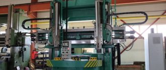
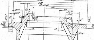
Dimensions of the working space of the lathe
The operating area is limited by the end of the spindle; end positions of the caliper, tailstock. The extreme positions of the carriage determine the maximum length of the turning, which are identical.
The diameters of the parts are limited by the distance between the guides or slides and the central axis.
Rice. 2. Working area 16K25 (caliper section)
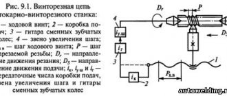
Electrical circuit diagram of a 16K25 screw-cutting lathe.
The electrical circuit diagram of the universal screw-cutting lathe 16K25 is shown in the following figure:
You can download a free electrical circuit diagram of a 16K25 screw-cutting lathe with specifications and in excellent quality from the link below:
the 16K25 screw-cutting lathe is shown in the following figure:
You can download this version of the electrical circuit diagram of a 16K25 screw-cutting lathe for free with specifications and in excellent quality from the link below:
Standard equipment
Let's look at the main components of the standard package.
Location of controls
Power is supplied by automatic switch 5 of the control panel, after which the signal lamp 6 lights up. The load level of the main engine is displayed by indicator 8. The electric cooling pump is started by switch 7.
On the front panel of the headstock there are handles:
- 1, 4 – rotation speed selection;
- 2 – selection of thread direction;
- 3 – select normal / increased step.
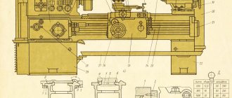
Passport for screw-cutting lathe 16K25.
This instruction manual for the “Universal screw-cutting lathe 16K25” contains information necessary both for the operating personnel of this machine and for the employee directly involved in working on this machine. This manual is an electronic version in PDF format of the original paper version. This documentation contains the Passport and Manual (instructions) for the operation of the universal screw-cutting lathe 16K25 . Contents of this documentation:
Contents of the Data Sheet for the screw-cutting lathe 16K25:
- Introduction
- Unpacking and transporting the machine
- Removing anti-corrosion coatings
- Machine installation
- Preparing the machine for start-up
- Machine lubrication
- Electrical equipment of the machine
- Pneumatic equipment of the machine
- Controls
- Starting up the machine and some operating conditions
- Instructions for the use and installation of chucks and steady rests
- Machine mechanics
- Brief description of the main components and their regulation
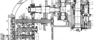
- Kinematic diagram of the machine
- Bearing layout diagram
- Typical possible malfunctions.
- Repair.
- Instructions for carrying out accuracy control
- Machine passport
- Applications
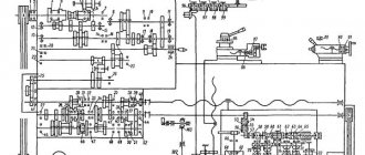
Kinematic scheme
For accuracy, we will divide the diagram into components.
Revolutions
The input shaft II of the gearbox receives torque from pulley 3, connected by a poly-V-belt to pulley 2 mounted on the end of the rotor of the electric motor M1. The spindle rotation side V is set by the engaged clutch of the double clutch 6.
When the left disks are compressed, forward revolutions are realized. The moment is transmitted through wheel 4 (5) to a double-crown block (8,9), then a three-crown block (13, 14, 15) is mated with one of the gears 10, 11, 12, a spindle double block (21, 22) with wheels 18, 19 respectively.
The search is activated by shifting the spindle unit to the right. The chain from shaft IV to V is closed by means of a block (23, 24) engaged with wheel 16 or 17, pair 25–27. Different positions of the blocks: (8, 9), (13, 14, 15), (21, 22) give 12 frequencies on the spindle, another 12 are obtained by enumeration.
When the right disks of clutch 6 are compressed, shafts II, III are connected through intermediate idler gears 28, 29, which reverse the direction of rotation. Further, the kinematics are identical to direct revolutions.
Rice. 4. Kinematics
Submissions
Each of the four possible movements of the caliper has its own kinematic branch: longitudinal, transverse feed, screw-cutting, high speed. Shaft VIII receives torque from the spindle through a transmission 20–32 or a step increasing unit (bringing), associated wheels 16, 33. From a reversing mechanism containing fixed wheels 30, 31; parasitic – 34, mobile – 35; through the guitar (a, b, c, d) the moment is transmitted to the receiving shaft X of the feed mechanism.
By switching clutches in different combinations with gear blocks, the speed of the final shaft of the XV feed box is changed. It transmits movement to the running shaft XVI or screw 61. The first option is obtained through two gear pairs mounted on bearings, an overrunning clutch 67, and fixed connected wheels 68, 64. In the second case, XV, 61 is connected by a clutch 60.
The rotation of the lead screw 61 is converted by a uterine nut mounted inside the apron into a linear movement of the carriage. By combining the switching of clutches and feedbox blocks, the required pitch is established. Part of the range is obtained by tuning the guitar by disconnecting the box with couplings 60, 116.
The shaft XVII of the apron mechanism receives movement from the running shaft with a sliding gear 65, along a chain 69 – 70 – 71, a coupling 72, a worm 73 connected to a wheel 74. By closing the cam coupling halves 77, 84, the direction of rotation of the XVIII with the wheel 94 is set. on a static rail 95, realizes the rectilinear movement of the carriage. Couplings 87, 90, connecting shaft XVII with screw 97, provide feed connection and reverse of the cross slide.
The rotation of the running shaft received from the motor 113 through the belt pair is converted into accelerated motion of the carriage. Thanks to the overrunning clutch 67, movement can occur with the box disconnected. Screws 97, 109 manually move the transverse, upper slide, rotating - 112, extend the quill.
Gearbox
Directly connected to the box are shafts II – VI with fixed wheels and four blocks. Bust ratio: 1:32; 1:8; 1:2; 1.25:1 provide 4 speed ranges: 12.5 – 40; 50 – 160; 200 – 630; 500 – 1600 rpm.
The mechanisms are located inside the headstock. Gears and shafts are made of chrome steel. The teeth are hardened, ground, and the ends are rounded to facilitate shifting. The splines are processed similarly.
The amount of torque transmitted by the friction clutch is regulated by tightening nuts 62, 59 (see Fig. 5) for forward and reverse revolutions, respectively.
When the rotation angle is more than 1/16, be sure to compare the torque with the permissible specification.
Technical characteristics of screw-cutting lathe 16K25.
| Quantities | ||
| Accuracy class | N | |
| The largest diameter of the workpiece being processed above the bed | mm | 500 |
| Largest turning diameter over cross slide | mm | 290 |
| The largest diameter of the processed bar | mm | 53 |
| Maximum length of the processed product | mm | 710, 1000, 1400, 2000 |
| Spindle speed limit | rpm | 12,5-1600 |
| Feed Limits | ||
| - longitudinal | mm/rev | 0,05-2,8 |
| - transverse | mm/rev | 0,025-1,4 |
| The greatest force allowed by the feed mechanism at the stop | ||
| - longitudinal | kgf | 800 |
| - transverse | kgf | 460 |
| The greatest force allowed by the feed mechanism on the cutter | ||
| - longitudinal | kgf | 600 |
| - transverse | kgf | 360 |
| Main drive motor power | kW | 11 |
| Machine dimensions (Length) | ||
| - length | mm | 2505, 2795, 3195, 3795 |
| - width | mm | 1190 |
| - height | mm | 1500 |
| Machine weight | kg | 2925, 3095, 3315, 3775 |
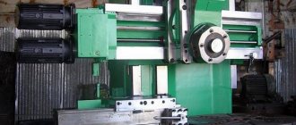
Headstock
Contains a gearbox, two intermediate shafts connected by a guitar to a feedbox. Spindle bearings are factory adjusted. Rigidity is satisfactory if a vertical load of 50 kgf applied under the flange causes a displacement of no more than 0.001 mm.
The first series of releases were equipped with: front support - class 4 double-row radial roller bearing with a tapered hole: 4-3182120. Rear – class 5 angular contact ball: 5-46216L. In later versions they were replaced by a double-row conical roller 4-697920L1, and an angular contact roller with springs on the outer ring 5-17716L.
Inside the housing there are tubes and distribution trays for centralized automatic lubrication. I20 oil is supplied to the spindle bearings, gears, and movable spline joints of the blocks.
Rice. 5. Reaming the spindle head
Gearbox
An independent unit located above the left cabinet. Kinematics (see 3.2). The unit, coupled with a pitch increasing chain and a replaceable guitar, provides 24 longitudinal / transverse feeds.
Precision thread processing is provided, bypassing the mechanics of the box, with the screw disconnected. The start of the fast motion engine is accompanied by automatic shutdown of the drive shaft by the activated freewheel. In order to increase the durability of the supports, rolling bearings are used throughout. Lubrication of friction pairs is automatic, by watering, oil supply from a separate pump.
Rice. 6. Section of the box
Repair of screw-cutting lathe 16K25
Below are links to three albums dedicated to the repair of a 16K25 screw-cutting lathe. This documentation was developed by the State Design and Technological Institute for Modernization and Automation, Repair of Metal-Cutting Machine Tools and Maintenance of Metalworking Equipment with Software Control - GPKTI STANCOSERVICE.
Contents “Repair of screw-cutting lathe 16K25. Album 1. General description"
- General description of the machine
- Purpose and brief technical characteristics
- Controls
- Specification of main components
- Basic parameters of gears, worms, screws, nuts, racks
- Kinematic diagram
- Specification of rolling bearings
- Machine lubrication
- Lubrication map
- Description of the electrical circuit
- Electrical circuit diagram
- Machine electrical equipment specification
- Drawings of machine components
- Bed 16K20.010.001; 16K20.011.001; 16K20.012.001; 16K20.016.001
- Spindle head 16K20.020.001
- Tailstock 16B20.030.001; 16B20P.030.001
- Four-position tool holder 16K20.041.001
- Carriage and support 16K20.040.001 and 16K20.050.001
- Apron 16B20P.061.000
- Feed box 16B20P.070.000
- Gearbox 16K20.080.001
Download for free “Repair of screw-cutting lathe 16K25. Album 1. General description" in normal quality (70 pages) can be found at the link below:
Contents “Repair of screw-cutting lathe 16K25. Album 2. Technological process of major repairs"
- Route of a 16K20 screw-cutting lathe during a major overhaul
- List of equipment used during major repairs of the machine
- Route technological process of disassembling the machine into units
- Recommendations for defect detection and restoration of parts
- Route technological processes for parts repair
- Requirements for the quality of machine assembly
- Route technological process for assembling machine components
- Route technological process of assembly and debugging of the machine
- Testing the machine after a major overhaul
- Protocol for checking the machine for rigidity and accuracy according to GOST 18097-72
- Noise Level Standards and Test Methods
- Applications
Download for free “Repair of screw-cutting lathe 16K25. Album 2. Technological process of major repairs" in good quality (100 pages) can be found at the link below:
Contents “Repair of screw-cutting lathe 16K25. Album 3. Replaceable parts"
- Temporary norms for the consumption of replaceable parts when repairing a 16K25 machine
- Working drawings of replacement parts
Download for free “Repair of screw-cutting lathe 16K25. Album 3. Replaceable parts" in good quality (196 pages) can be found at the link below:
Apron
The housing contains four pairs of cam coupling halves, manufactured integrally with the gears. The combination of inclusions ensures forward and reverse movements of the carriage and caliper slide. When threading, half of the uterine nut 62 is brought in until it mates with the lead screw profile.
The interlocks protect against the simultaneous start of the drive shaft, screw, and two feeds. The generated feed force is adjusted using nut 11 using a dynamometer. The design of the feed cut-off unit guarantees a stop accuracy of 50 microns.
Rice. 7. Apron cuts
Caliper
The cross layout allows for longitudinal movement along the bed guides and transverse movement of the slide along the carriage guides. Starting the mechanical cross feed disables the handwheel 33.
A four-position tool holder 43 is mounted on a tool slide 9, which moves manually along the guides of the rotating part 10. The tool holder is rotated using a handle 4 and is stably fixed with an accuracy of 5 microns. A rear holder 6 can be installed on top of the caliper slide to speed up cutting work.
Rice. 8. Cross section of the caliper
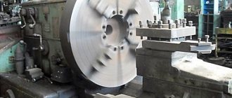
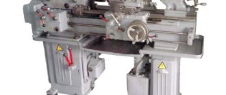
Screw-cutting lathe mod. 16K25 RMC 750-2000mm.
Screw-cutting lathe 16K25
designed for performing a variety of turning operations: turning and boring cylindrical and conical surfaces, cutting external and internal metric, inch, modular and pitch threads, as well as drilling, countersinking, reaming, etc. Deviation from cylindricity is 7 microns, taper is 20 microns at a length of 300 mm, deviation from straightness of the end surface at a diameter of 300 mm is 16 microns.
The 16K25 screw-cutting lathe is a lightweight version of the 16K20 machine with an increased diameter of the workpiece. The diameter of the workpiece has increased from 400mm. up to 500mm.
The machines are equipped with a mechanical clutch, a drive for rapid movements of the caliper, the tailstock has aerostatic unloading, the bed guides are hardened HRCе 49...57.
The technical parameters by which screw-cutting lathes are classified are the largest diameter D of the workpiece (part) being processed or the height of the centers above the bed (equal to 0.5 D), the greatest length L of the workpiece (part) being processed and the weight of the machine. A number of the largest processing diameters for screw-cutting lathes look like: D = 100, 125, 160, 200, 250, 320, 400, 500, 630, 800, 1000, 1250, 1600, 2000 and further up to 4000 mm. The greatest length L of the workpiece is determined by the distance between the centers of the machine. Manufactured machines with the same value of D can have different values of L. By weight, lathes are divided into light - up to 500 kg (D = 100 - 200 mm), medium - up to 4 tons (D = 250 - 500 mm), large - up to 15 t (D = 630 - 1250 mm) and heavy - up to 400 t (D = 1600 - 4000 mm). Lightweight lathes are used in tool production, instrument making, the watch industry, and in experimental and experimental workshops of enterprises. These machines are available with or without mechanical feed.
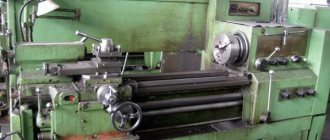
Tailstock
The pressed headstock moves manually. It is secured by a bar 31, which presses the plate 28 against the guides, when the lever 19, mounted on the eccentric 20, connected by a rod 25 to the bar, is turned towards itself. An air supply is provided for the aerostatic cushion, which reduces the required displacement force to 5 kgf, eliminating the formation of scoring.
The rotation of the steering wheel 12, mounted on the screw 5, is transformed by the nut 6 into the movement of the quill 3. The extension is controlled on a reference scale 11 with a stroke value of 0.1 mm, the maximum stroke is 150 mm. The quill is bored to a Morse taper No. 5, locked with handle 48. Body 2 can be shifted across with screws 41 by ± 15 mm, turning flat cones. The initial alignment with the spindle is ensured by the alignment of plates A in the same plane.
Rice. 9. Tailstock