Basic methods for checking a lathe
When checking a lathe for accuracy, the main checks are the bed guides, spindle runout and lead screw.
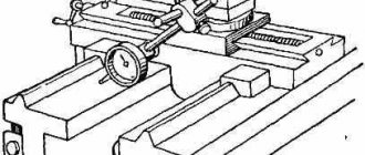
The bed guides must be straight in the longitudinal direction. When worn, grooves, scratches, and sometimes nicks appear on them. Wear can be detected by superficial inspection and using measuring tools. To determine its value, install the test ruler 1 (Fig. 255) one by one on the guides 2, then determine the gap between their surfaces and the ruler in the light and measure with a feeler gauge.
The following wear of the frame is considered acceptable: with a center height of up to 300 mm - 0.02 mm over a length of 1000 mm; with center heights greater than 300 mm - 0.03 mm at the same length. For new or repaired machines, only a convexity of the bed, but not a concavity, is allowed by this amount.
The bed guides for the tailstock must be parallel to the carriage guides. Check the parallelism with an indicator mounted in the tool holder on the carriage (Fig. 256), which is moved along the frame; The indicator pin rests against the tailstock guide. The permissible deviation is up to 0.01 mm for machines with a center height of up to 200 mm and up to 0.02 mm for machines with a center height of more than 200 mm.
The horizontality of the frame guides is checked with a level, as shown in Fig. 257, moving ruler 2 with level 1 along the frame guides. The permissible deviation is 0.05 mm over a length of 1000 mm.
The spindle axis must be parallel to the bed guides in the vertical and horizontal planes. To check, insert a test mandrel into the conical hole of the spindle and check it with an indicator for the absence of runout along its entire length. Then the indicator is secured to the carriage and installed so that the indicator pin touches the mandrel, first in the vertical (Fig. 258, a) and then in the horizontal (Fig. 258, b) plane. With each installation, moving the carriage along the mandrel to a length of 300 mm, note the deviations of the indicator, which should not exceed 0.01 mm in the vertical plane for machines with a center height of up to 200 mm and 0.02 mm for machines with a center height of up to 400 mm. In the horizontal plane, indicator deviations should not be more than 0.01 mm for machines with any center height.
Deviation of the mandrel, counting to the right of the headstock, is allowed in the vertical plane only upward, and in the horizontal plane - only towards the cutter.
The spindle journals should rotate without wobbling. The spindle is checked for runout using an indicator mounted in the cutting head. When checking, it is necessary that the pin 1 of the indicator rests on the neck 2 of the spindle (Fig. 259, a). The permissible deviation is 0.01 mm for center heights of up to 350 mm and 0.02 mm for center heights of more than 350 mm.
The spindle must not have axial movement during rotation. The check is carried out as in the previous case, but the pin 1 of the indicator (Fig. 259, b) is pressed against the end of the collar 2 of the spindle. The permissible deviations are the same as when checking the journal runout.
The top of the front center should not have any runout when rotating. To check, the indicator is fixed in the cutting head (Fig. 259, c) and its pin 1 is pressed against the center cone 2. The permissible deviations are the same as in the previous two cases.
The pitch accuracy of the lead screw is checked using an accurate threaded mandrel 1, installed between the centers of the front and rear stock (Fig. 260), and an accurate cylindrical nut 2, screwed onto the threaded mandrel. The nut 2 has a longitudinal groove into which the ball of the holder 3, which carries the indicator 4 and is fixed in the machine support, is inserted. The tip of the indicator rests against the end of the nut, which is held from rotation by the ball of the holder. The machine is adjusted to the mandrel thread pitch. Having started the machine with the split nut turned on, monitor the indicator readings. Permissible deviations: 0.03 mm at a length of 100 mm and 0.05 mm at a length of 300 mm for machines with center heights up to 400 mm.
Practical testing of lathe accuracy. In addition to the geometric checks discussed, a comprehensive practical check of the accuracy of the lathe is carried out. The purpose of the test is to assess the accuracy of the machine in operation when manufacturing parts with cylindrical and end surfaces. During this check, the resulting deviations in ovality, taper and flatness are determined, which should not exceed the deviations established by GOST: ovality 0.01-0.02 mm and taper 0.02 mm over a length of 1000 mm and concavity of the end no more than 0 .02 mm on a diameter of 300 mm.
Scheduled Maintenance
Scheduled maintenance and necessary repairs are carried out by qualified, specially trained repair team personnel. As a rule, planned work is more extensive than routine maintenance, and may include work on disassembling entire components of machines and mechanisms. That is why competent mechanical specialists are required.
Planned repairs and maintenance are a regulated type of work. This includes:
- checking equipment performance;
- adjustment and regulation of basic characteristics;
- cleaning clogged working parts of equipment and mechanisms;
- changing filters and oil;
- identification of violations and malfunctions of equipment.
Data on changes in the operation of serviced mechanisms during maintenance are necessarily recorded: in inspection cards, repair logs, in a computer database, etc.
Technological cards for maintenance, replacement of lubricant, specifications for material consumption, when scheduled or routine maintenance are carried out, have proven themselves very well. With their help, repair specialists easily learn information about the frequency and list of necessary work.
Since certain types of maintenance and repair do not have a standard manual, the main documents are developed within a separate system. Moreover, a certain type of industrial equipment requires its own list of works. For maximum convenience, enterprise equipment is divided into groups to facilitate the development of maintenance methods for them.
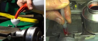
Can compressed air be used when cleaning a CNC machine?
During daily maintenance of a CNC machine, it is important not only to perform the work efficiently, but also to apply as little effort as possible and spend as little precious working time as possible. Using a compressed air gun frees hard-to-reach areas of the CNC machine structure from dust and chips much faster, which allows cleaning to be done several times faster
However, manufacturers of CNC machines strongly discourage the use of compressed air during maintenance and cleaning, and there are several reasons for this:
- Dust and dirt, including that generated during the processing of MDF and lifted from the concrete floor, have good abrasive properties. By getting under high pressure jets of compressed air even into closed bearings of electric spindles, ball screws, linear guides and other mechanisms, abrasive dust significantly reduces their service life.
- Dust flying in a stream of compressed air can penetrate the electronic components of a CNC machine and settle on electrical contacts. After some time, the density of the layer of dust deposited on the contacts can reach a level at which the electronic device fails.
- Compressed air may contain drops of water, which, if they get on exposed metal parts of the machine, can cause corrosion, when interacting with the contacts of electrical switches and relay devices, they can cause oxidation, and if they penetrate inside complex electronic devices, they can cause a short circuit.
- The efficiency of dust collection with compressed air tends to zero, since lightweight fractions rise and hang in the air, and after some time settle on the surfaces of the CNC machine, on the floor, on workpieces, thereby making cleaning not only useless, but also inappropriate.
- Dust particles from wood chips and concrete floors raised into the air, entering a person’s lungs, are harmful to his health.
As a rule, when performing operations and maintenance of a CNC machine in the production of furniture and MDF facades, compressed air is used as the fastest and most effective way to clean work tables from chips and dust. To clean the remaining parts of the CNC machine using compressed air, you should follow some recommendations:
- You can only blow air on the milling spindle when the CNC machine is turned on. The fact is that modern spindles are connected to a compressed air system, which creates a high-pressure area inside them, thereby preventing dust from entering the bearings. Directing a jet of compressed air into the electrospindle shaft is prohibited.
- A chuck (mandrel) with any tool must first be installed in the quick tool change mechanism of the milling spindle.
- Near the location of bearings and electrical devices, a compressed air gun should be used at a maximum distance, sufficient only to blow off small loose fractions.
- It is prohibited to direct a jet of compressed air at the impellers of the spindle cooling systems or the electrical cabinet of the CNC machine.
- Before using a compressed air gun, you still need to use a vacuum cleaner, brush or cloth.
Thus, if these recommendations are followed, daily maintenance of the CNC machine will indeed be useful, including to ensure uninterrupted operation of the equipment and extend its service life.
Routine Maintenance
Various types of routine maintenance are performed by the site or workshop's own production personnel and include hourly and shift monitoring of equipment operation, inspection, lubrication, etc. From the point of view of the number of staffing units, this is reasonable and rational, since there is no need to increase the number of repair service workers. On the other hand, this method allows existing operators to expand their knowledge of the operating principles and technical design of industrial equipment.
As a rule, routine maintenance of equipment is not regulated and involves:
- strict implementation of all operating rules specified in the technical documentation of the manufacturer;
- regulation of a certain operating mode of equipment and prevention of overloads;
- compliance with temperature conditions;
- strict lubrication intervals in places where technical documentation requires it;
- monitoring the state of wear of mechanisms and components during visual inspection;
- instant shutdown of electrical equipment in an emergency.
Lathe installation
To install the machine, it is necessary to install a concrete foundation 30 days before operation. The calculation of the installation height of the lathe must be in accordance with the Operating Manual. If necessary, our company’s specialists will install the lathe on vibration supports.
The range of services for installation of a lathe also includes the following work:
- Assessment work at the installation site;
- Calculation of the foundation for a lathe;
- Drawing up installation drawings;
- Pouring the foundation for the machine;
- Leveling equipment with a level;
- Installing the lathe on the foundation.
CNC Machine Preventive Maintenance
This link is leaving the site.
- Company About
- Blog
- Career
- Core Values
- Places
- News & Events
- our history
- strategic partners
- Reviews
- by manufacturer Acer
- 3D printing/additive manufacturing
CNC turning centers
- by category Abrasives
Replaceable cutters
- Custom Robotic Systems
- Applied mechanical engineering
- Training Haas Class Description
- Robotic success stories
- Calculators
- Financing
- Contact us
- MN - 800.328.3272
- IA - 800.327.1123
- NE - 800.626.3369
MMT/Moncktons Machine Tools is a division of Productivity Inc and serves the Rocky Mountain region including CO, ID, MT, NM, WY and UT. Click on the MMT/Moncktons logo to visit their website. Online order
- MN - 800.328.3272
- IA - 800.327.1123
- NE - 800.626.3369
- Financing
- Contact us
- Search
- Company About
- Blog
- Career
- Core Values
- Places
- News & Events
- our history
- strategic partners
- Reviews
- by manufacturer Acer
- 3D printing/additive manufacturing
CNC turning centers
.
Types of repairs
Repair work is carried out in order to maintain the operational characteristics of turning equipment and is of two types: planned and unscheduled. The first ones are carried out only on the basis of preventive maintenance schedules. For 16K25, four types of work are provided, including inspection and three types of repairs:
- small;
- average;
- capital.
According to clause 17.2 of the “Operating Manual” of the 16K20 lathe, its turnaround period (working time before the first overhaul), subject to compliance with the manufacturer’s operational requirements, is 10 years with two-shift operation. During this period, six scheduled inspections 16K20, four minor repairs, one medium (in the middle of the period) and one major (at the end of the period) must be performed.
The need for unscheduled repair work usually arises when the permissible parameters of equipment suddenly decrease or fail. This usually happens when the manufacturer’s specifications for the operation and maintenance of turning equipment are not met. At production enterprises, all types of work are carried out according to maintenance schedules by qualified personnel of specialized repair departments. In small enterprises, repairs to a lathe are carried out with their own hands as problems arise with its accuracy and performance.
Small repairs
This type of repair work is carried out both according to the approved nomenclature and according to the results of observations of turning equipment during shift and periodic maintenance. Its purpose is to ensure the operation of turning equipment until the next scheduled repair.
According to clause 17.3.3 of the “Operating Manual” of the 16K20 lathe, during minor repairs the following types of work are mandatory:
- identifying faults for elimination during subsequent scheduled repairs;
- measurements of equipment geometry for certified accuracy;
- idle tests;
- noise and temperature tests;
- checking the accuracy and purity of processing.
Small repairs
The rest of the work from the list given in the Manual is carried out only if necessary, depending on the condition of the equipment. Based on the results of minor repairs, a statement of the condition of machine parts is compiled for inclusion in the work that follows the scheduled maintenance work.
Medium renovation
This type of repair work includes work according to the list of recommendations for minor repairs, as well as partial disassembly of the turning 16K20, during which the functionality of the main mechanisms and assemblies is restored. Such repairs for the 16K20 screw-cutting lathe are carried out according to the list given in paragraph 17.3.4 of the “Operating Manual”.
During an average repair, the accuracy is checked before and after disassembling the turning equipment, the spindle rigidity is checked, and the wear of the friction surfaces is measured before and after their restoration. The average repair of a lathe is performed in the middle of the overhaul period. Its goal is to restore the service life of turning equipment to such a level that the machine can operate until a major overhaul.
Major renovation
According to clause 17.3.2. In the “Operating Manual”, a major overhaul of the 16K20 lathe is preceded by an inspection of the condition of the machine equipment. During the inspection, inspection data from previous repair work is checked, lists of parts for restoration and replacement are determined, and working drawings are produced for ordering replacement parts.
Overhaul of machine 16K20
After complete dismantling of all mechanisms, each part is cleaned, after which they are inspected and compared with the defective list. The overhaul involves the restoration of all passport characteristics of 16K20. Therefore, lathes after a high-quality overhaul have the same parameters as new turning equipment, and their overhaul period is also ten years.
What is included in the maintenance of machines and equipment
Standard list of works for maintenance and diagnostics of metalworking machines:
- visual assessment of wear on the guide frames of carriages, as well as other surfaces subject to friction, for example, traverses;
- tightening loose fasteners;
- checking the speed and direction of switching handles;
- assessing the effectiveness of machine safety devices, such as guards;
- checking the quality of tension of tapes, belts and operating chains;
- checking clamps, cams and other clamping devices, which must be as reliable as possible;
- monitoring the degree of noise and vibration of equipment;
- measurement of bearing heating;
- inspection for the absence of leaks, hydraulic or pneumatic shocks during the working process, correct operation of the coolant supply system.
Work that must be carried out strictly by a professional with the appropriate skills and experience:
- checking rotating joints by opening the covers of mechanisms and components;
- correcting the degree of tension of spring mechanisms, replacing parts that show signs of wear;
- testing of clutches and brake mechanisms;
- adjustment of spindle bearings and clearances in screw pairs;
- replacement of worn parts or (if they can still serve) appointment of their replacement during the next planned or major repair.
Main working units
The main components of a screw-cutting lathe in the figure below are highlighted with text in a detailed description:
- All main components of the machine are mounted on the bed.
- The front unit (headstock) is a starting device for rotating the workpiece. Its housing contains a gearbox.
- The rear assembly (headstock) holds the drill, zinc and reamer when machining holes.
- The drive shaft and lead screw are put into operation by the feed box. It also changes the number of their revolutions.
- The converter of the rotational movements of the drive shaft and screw into the rectilinear movement of the caliper is the apron.
- The caliper, in turn, moves the cutter on the cutting head.
The main difference between a lathe and a screw-cutting lathe is the presence or absence of one part - a lead screw. In the latter, this part is present, thanks to which the device can perform thread cutting with a cutter.
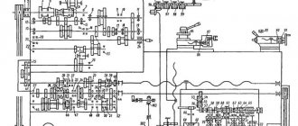
A schematic diagram of a screw-cutting lathe with the designation of all the main components and fasteners is shown below in the figure.
Maintenance terms
Types and terms of maintenance are calculated in days or months, and this depends on the complexity and type of industrial equipment. So, for example, calculations for traction rolling stock (diesel locomotives, electric locomotives, etc.) are made according to the average values of overhaul runs.
The frequency, types and timing of maintenance are calculated according to the calendar operating time and take into account the technical conditions of the manufacturing plants.
Thus, as a result of a small analysis of the essence, classification, types of maintenance of industrial, production and technological equipment, we can conclude that it is necessary, systematic and mandatory strict control. It is the combination of these components that will allow enterprises to achieve uninterrupted operation of machines and mechanisms, which, in turn, helps to save the budget, increase labor productivity and generate additional profits.
Safety precautions when working on a screw-cutting lathe
Before starting work, the turner must perform the following steps:
- To prevent clothing from falling under the operating moving elements of the machine, it must be tucked in. Long hair should be covered with a headscarf and the cuffs should be turned up. It is also prohibited to approach a working unit with bandaged limbs;
- ground the machine;
- in order not to stumble while working at the machine, the grid under your feet must be secured and stable;
- Lead screws and rollers need to be lubricated. The oil level should also be checked in the gearbox and in the oil reservoir;
- the serviceability of the main devices needs to be checked idle;
- If there are malfunctions in the work, you must immediately inform the technician.
When performing work it is important:
- use protective glasses, screens and shields;
- use a special brush to remove excess chips from the main components and parts;
- It is unacceptable to stop a working cartridge by hand;
- Do not place parts, tools or other objects on the operating device;
- the gearbox does not shift while driving;
- It is prohibited to work with faulty devices, as well as random devices.
After completing the work you must:
- immediately disconnect the screw-cutting lathe from the power supply;
- clean the main bonds from debris and metal shavings;
- lubricate all moving parts and the surface of the machine with oil to protect it from corrosion;
- repair and restoration of the machine is carried out after the permission of the chief foreman, subject to the rules of safe operation.
Classification of types of maintenance
According to the stages of operation, repair and maintenance are divided into:
- Maintenance during storage.
- Maintenance when moving.
- Maintenance during operation.
- THAT while waiting.
By frequency:
- Periodic maintenance.
- Seasonal maintenance.
According to operating conditions:
- THAT under special conditions.
According to the regulation of implementation:
- Regulated service.
- Periodic control.
- Constant control.
- Stream service.
- Centralized service.
- Decentralized service.
On organization of implementation:
- Maintenance by operating personnel.
- Maintenance by specialized personnel.
- Maintenance by the operating organization.
- Maintenance by a specialized organization.
- Maintenance by the manufacturer.
By maintenance methods:
- In-line maintenance method.
- Centralized maintenance method.
- Decentralized maintenance method.
By executive organization:
- operating personnel,
- specialized personnel,
- operating organization,
- specialized organization
- by the manufacturer.
Lathe rigging
Rigging work includes: loading, moving, unloading equipment.
The lathe has a large mass. Therefore, during work it is necessary to comply with technical safety rules. Lathes weigh from 300 kg to 5 tons
Before you begin rigging the machine, you need to make accurate technical calculations, measurements of units and openings, and take into account the technical characteristics of the equipment. Draw up a transportation plan so as not to clutter up the site where the lathe is planned to be installed and not to paralyze production.
Experienced specialists of our company will carry out professional rigging of the lathe using lifting equipment and equipment (turnbuckles, ropes, belts, slings, chains, trolleys, forklifts and truck cranes).
Basic rules for rigging work:
- The workspace must be equipped with flooring and racks for spare parts;
- Large elements are screened with a wooden frame and signal flags are glued on;
- Moving units are fixed in a static, stationary state;
- Auxiliary parts (nuts, fasteners) are packaged in separate cases with tags.
Maintenance Tasks
It is safe to say that maintenance is a defining preventive action that is essential to ensure the continuous operation of production equipment and mechanisms in the time intervals between planned repair procedures. It involves caring for and monitoring the operation of machines, maintaining them in good working order, scheduled technical inspection, cleaning, washing, adjusting, purging and other equipment repairs.
Certain types of maintenance can be carried out directly on operating equipment using breaks and days off. If there are appropriate permits in the operating instructions for machinery and equipment, it is possible to briefly disconnect them from the power supply until they come to a complete stop. In such cases, some downtime is allowed, but so that production and technological processes are not interrupted.
Typical control unit
When considering a modern universal screw-cutting lathe, you should pay attention to the control unit. To indicate the main processing parameters, levers and handles, buttons and other control units are installed
The main features include the following points:
- As a rule, a handle is installed to indicate the number of revolutions. A universal modern screw-cutting lathe can change this indicator, which is selected depending on the required cutting conditions.
- A screw-cutting lathe has a device that allows the formation of a threaded surface. Its parameters are set using a special control unit. Do not forget that some parameters can be set solely by installing the required replacement wheels.
- There are also handles that allow you to control the caliper. Screw-cutting lathes have main components that allow mechanical feed for quick positioning and processing with a constant movement speed.
Controls of screw-cutting lathes using the example of model 16K20
The CNC screw-cutting lathe has a more complex layout. This is due to the fact that such equipment can operate without operator intervention at intermediate stages.
Maintenance and repair system
The main task of automated systems, which carry out various types of maintenance, is to reduce costs for this item of the enterprise budget and significantly increase the reliability class of machines and mechanisms, which helps to reduce the cost of manufactured products and, accordingly, increase income.
In the case of repairs, the task changes, since it is necessary to minimize not only losses, but also the frequency of the work itself (regardless of the type and volume). The ideal scheme that enterprises are striving for is a complete rejection of emergency repairs, which inevitably lead to unscheduled shutdowns of production.
In addition, operation and maintenance, in particular repair work, are carried out under conditions of some uncertainty. Even monitoring of the wear and tear of industrial equipment and many years of experience cannot determine the specific volume and indicate the range of new spare parts for equipment. But the conveyor system involves the precise distribution of the necessary parts that may be required from the warehouse for a specific order.
Specifications
| Characteristic name | Meaning |
| Main settings | |
| Accuracy class according to GOST 8-82 | N |
| Largest workpiece diameter over: | |
| bed, cm | 44.5 |
| caliper, cm | 22 |
| bed recess, cm | 62 |
| Maximum length: | |
| blanks, cm | 150 |
| turning, cm | 140 |
| Spindle parameters | |
| Diameter of through hole, cm | 5.4 |
| Direct rotation frequency, rpm | 10-1400 |
| Reverse rotation frequency, rpm | 16-1800 |
| Volume of the inner cone in the spindle | M5 |
| Spindle end according to GOST 12593-72 | 6K |
| Feed Options | |
| Maximum movement of the caliper carriage: | |
| longitudinal, cm | 140 |
| transverse, cm | 28 |
| Feed rate limits: | |
| longitudinal, mm/rev | 0,018…22,4 |
| transverse, mm/rev | 0,009…11,2 |
| Speed of fast movements of the caliper, longitudinal/transverse, cm/min | 400/2 |
| Longitudinal shift by one division: | |
| limb, mm | 1 |
| vernier, mm | 0.1 |
| Transverse movement of the caliper by one division of the dial, mm | 0.05 |
| Number of threads applied: | |
| metric | 36 |
| inch | 45 |
| modular | 36 |
| pitching | 45 |
| Overload fuse | present |
| Blocking longitudinal and transverse feeds | present |
| Switching longitudinal stops | present |
| Roughness of the part when grinding clean, microns, no more | Ra 2.0 |
| Tailstock parameters | |
| Maximum length of movement of the tailstock quill, cm | 15 |
| Maximum distance of movement of the tailstock, cm | ±1,5 |
| Parameters of built-in electrical equipment | |
| Number of electric motors on the machine | 3 |
| Main drive electric motor, kW | 7.5 |
| Drive of accelerated movements, kW | 0.75 |
| Cooling pump electric motor, kW | 0.12 |
| Overall dimensions and weight of the machine | |
| Machine dimensions (l ˣ w ˣ h), cm | 280 ˣ 119 ˣ 145 |
| Machine weight, t | 2.43 |
Varieties and design features
There are actually a lot of machines and they perform all kinds of metal processing operations, but we will highlight the most famous types
Multi-incisor
Designed for processing complex parts made from pipes, shaped profiles or rods of different sections. Multi-cutter or multi-spindle machines are mainly used in batch production.
Performed operations:
- drilling;
- thread;
- turning;
- pruning;
- boring;
- countersinking;
- deployment.
Multi-cutting machines have high productivity due to the large area of the drive mechanism, rigidity of the structure, and the ability to perform several operations simultaneously.
Carousel
A group of machines for working with large-sized parts and workpieces. The parts processed on them are short in length, but have significant weight and diameter.
Features of carousel models:
- used for processing conical or cylindrical surfaces;
- grooves of various configurations are made;
- You can also do grinding, milling, trimming ends;
- thread cutting.
In addition to the basic elements of any lathe, this type has additional equipment:
- table with faceplate;
- racks for moving the traverse.
Backing
The machines are designed for processing the back surfaces of tool teeth. It can also be used to perform other turning operations. The backing machine is distinguished by its special support design. The part is backed up as follows:
- rotational movement of the part;
- reciprocating movement of the cutting tool towards the part.
Screw-cutting
The most common group of machines. Widely used in serial and individual production. Screw-cutting models can be found in workshops, schools, and in any industry. They are easy to operate and maintain.
REFERENCE! The screw-cutting lathe is a universal model for all kinds of processing of metal workpieces. It can be used to make various types of threads: modular, inch, metric.
Structural elements:
- bed;
- front and rear stock;
- caliper;
- apron;
- gearbox.
Revolver
Revolver group machines are designed for processing parts from calibrated rods. Operations that can be performed on this equipment:
- turning;
- boring;
- shaped turning;
- countersinking;
- drilling;
- thread formation;
- deployment.
REFERENCE! The name of the machines in this group comes from a special holder. It can be driven or static. The drive type gives more possibilities for carrying out various operations.
Universal
Universal lathes include screw-cutting machines, since they can perform almost any metal operation.
Main technical characteristics of the universal machine:
- rotation speed (number of revolutions); accuracy class; it is indicated in the product labeling with the letters S, B, N, A, P;
- number of gears;
- what sizes of parts can be installed;
- weight and dimensions of the machine;
- the amount of feed and maximum movement along the axis.
Conditional separation of equipment
The first division is carried out in accordance with the general status of the equipment as part of the main equipment of the enterprise:
- technological;
- electrical;
- lifting and transport, etc.
Next, the numerous technological equipment of the enterprise, which is of greatest interest to the repair team, is divided into subgroups:
- metal-cutting equipment;
- forging and pressing equipment;
- foundry equipment;
- woodworking equipment, etc.
Within the listed types of equipment, it is much easier to identify objects for characterization and implementation of repair work, as well as certain types of maintenance.