Information about the manufacturer of 6P series cantilever milling machines
Manufacturer of 6P series milling machines is the Gorky Milling Machine Plant, GZFS , founded in 1931.
Products of the Gorky Milling Machine Plant GZFS
- 6M12P
vertical cantilever milling machine 320 x 1250 - 6M13P
vertical cantilever milling machine 400 x 1600 - 6M82
universal horizontal milling machine 320 x 1250 - 6M82G
horizontal cantilever milling machine 320 x 1250 - 6М82Ш
universal cantilever milling machine 320 x 1250 - 6M83
universal horizontal milling machine 400 x 1600 - 6M83G
horizontal cantilever milling machine 400 x 1600 - 6N12
vertical cantilever milling machine 320 x 1250 - 6N13P
vertical cantilever milling machine 400 x 1600 - 6N82
horizontal cantilever milling machine 320 x 1250 - 6N82G
horizontal cantilever milling machine 320 x 1250 - 6Р12, 6Р12Б
vertical cantilever milling machine 320 x 1250 - 6Р13, 6Р13Б
vertical cantilever milling machine 400 x 1600 - 6Р13Ф3
vertical cantilever milling machine with CNC 400 x 1600 - 6Р82
universal horizontal milling machine 320 x 1250 - 6R82G
horizontal cantilever milling machine 320 x 1250 - 6Р82Ш
universal cantilever milling machine 320 x 1250 - 6Р83
universal horizontal milling machine 400 x 1600 - 6R83G
horizontal cantilever milling machine 400 x 1600 - 6Р83Ш
universal cantilever milling machine 400 x 1600 - 6T12-1
vertical cantilever milling machine 320 x 1250 - 6T12
vertical cantilever milling machine vertical 320 x 1250 - 6T12F20
vertical cantilever milling machine with CNC 320 x 1250 - 6T13
vertical cantilever milling machine 400 x 1600 - 6T13F20
vertical cantilever milling machine with CNC 400 x 1600 - 6T13F3
vertical cantilever milling machine with CNC 400 x 1600 - 6T82
universal horizontal milling machine 320 x 1250 - 6T82-1
universal horizontal milling machine 320 x 1250 - 6T82G
horizontal cantilever milling machine 320 x 1250 - 6Т82Ш
universal cantilever milling machine 320 x 1250 - 6T83
universal horizontal milling machine 400 x 1600 - 6T83-1
universal horizontal milling machine 400 x 1600 - 6T83G
universal horizontal milling machine 400 x 1600 - 6Т83Ш
universal cantilever milling machine 400 x 1600 - 6606
longitudinal milling machine 630 x 2000 - GF2171
vertical milling machine with CNC and ASI 400 x 1600
Technical characteristics and markings
All processing machines are divided according to the following characteristics:
- number of switching speeds;
- rotation frequency;
- number of revolutions of the working head (usually 400-3500 revolutions per minute);
- installation power (affects processing speed);
- features of the table movement in vertical and horizontal directions;
- feeding method (manual / mechanical);
- manual or electronic control;
- presence of a cooling system, CNC.
Different types of cutters can be used. Angular - to obtain the required part configuration. End - for vertical processing of workpieces (a profile structure is formed). Planar and cylindrical - for surface treatment, removing a layer of a certain thickness. The latter type of cutters can have a different number of teeth.
When choosing a milling unit, consider the type of equipment - look at the markings:
- cantilever vertical milling machine “1”;
- working on a flow (continuous action for the manufacture of similar parts) “2”;
- stencil (copying) “3”;
- engraving equipment “4”;
- non-console with cross table “5”;
- longitudinal milling (rarely used) “6”;
- universal for a wide range of applications (used for piece production, workshops) “7”;
- horizontal console “8”;
- others "9".
The marking indicates the type of base model. "W" stands for broad versatility. “B”, “P”, “A”, “C” show the accuracy class. “G” indicates the horizontal orientation of the working spindle.
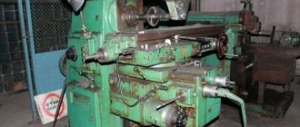
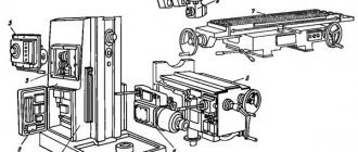
Feed box for 6P series milling machines. Purpose, scope
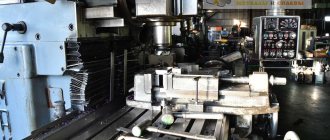
Cantilever milling machines of the P series have been produced by the Gorky Milling Machine Plant (GZFS) since 1972. The machines are similar in design, widely unified and are a further improvement of similar machines of the H series .
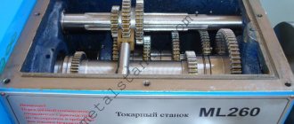
Design and principle of operation of the feed box of 6p series milling machines
The feed box is an independent unit mounted on the left side of the console. It is the same for the entire range of machines - 6Р12, 6Р12Б, 6Р13, 6Р13Б, 6Р82, 6Р82Г, 6Р82Ш, 6Р83, 6Р83Г, 6Р83Ш.
The feed box provides working movements of the table along 3 coordinates.
The feed movement is produced by the M2 electric motor (N = 2.2 kW; p = 1430 rpm). The feed box of the machine allows mechanical movement of the table in three directions:
- longitudinal (perpendicular to the spindle axis)
- transverse (parallel to the spindle axis)
- vertical
Special locking devices ensure that several movements cannot be activated simultaneously.
Eighteen longitudinal feeds are carried out according to the following scheme: electric motor M2, constant transmission (26/50)(26/57), triple moving block (18/36)(27/27)(36/18), second triple block (18/40) (21/37)(24/34), X shaft.
From shaft X, motion can be transmitted either to shaft XI, either directly through the wheels (40/40) (clutch M2 is on), or through overdrive (13/45)(18/40)(40/40) (M2 is off).
Further movement is transmitted according to the following scheme: shaft XI, gear (28/35), shaft XII, gears (18/33)(33/37)(18/16)(18/18), lead screw with a pitch of 6 mm.
Transverse and vertical movements of the table are carried out in a similar way by two other lead screws.
Equations of kinematic chains for the maximum and minimum values of longitudinal feed:
Smax = 1430·(26/50)(26/57)(36/18)(24/34)(40/40)(28/35)(18/33)(33/37)(18/16)( 18/18) 6 = 1250 mm/min
Smin = 1430·(26/50)(26/57)(18/36)(18/40)(13/45)(18/40)(40/40)(28/35)(18/33)( 33/37)(18/16)(18/18) 6 = 25 mm/min
Rapid movement of the table in all three directions is carried out from the same electric motor without a feed box, directly through a gear train (26/50)(50/67)(67/33), an M4 friction clutch on shaft XI and further along the kinematic chains of working feeds. In this case, the M3 dog clutch is turned off and the M4 friction clutch is turned on.
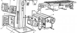
Feed box couplings of a cantilever milling machine
In Fig. 12.6 shows the couplings of the last shaft XI of the machine feed box. On the left side of the shaft there is a ball safety clutch 1 with a toothed rim (z = 40). The working feed is carried out when the claw clutch 7 is turned on to the extreme left position, when its cams engage with the cams of the safety ball clutch. In this case, the movement from the gear 8 (z - 40) is transmitted to the gear ring of the safety clutch and then to the jaw clutch 7, which is installed on the shaft XI on a sliding key.
When clutch 7 moves to the right, its cams are separated from the cams of the safety clutch, and the working feed stops. With further movement to the right, clutch 7 engages friction clutch 6, and shaft XI receives rapid rotation from wheel 5 (z = 67) through gear 4 (z = 33), friction clutch housing 3 and compressed friction discs 2.
Turning on the high speed table of a console milling machine
The feed box has a single-handle selective control (Fig. 12.7). Feed switching is carried out by moving gear blocks or individual gears using forks mounted on the corresponding racks. The racks receive longitudinal movement from two disks with holes, mounted on the same axis with the shift handle. The slats that move the blocks can occupy three different positions relative to the disks.
Feed switching mechanism diagram
In Fig. Figure 12.8 shows a diagram of the operation of this mechanism using the example of switching a triple block of gears. In position I, rack 1 rests on disk 3, and rack 2 passes through the holes of both disks 3 and 4. In position II, both racks enter the holes of disk 3. Position III is the opposite of position I. Between the racks there is a gear 5, which provides coordinated movement of the slats.
To set the required feed, the shift handle with the disks is first pulled out of the feed box, then turned to the right or left around the axis to the required position until the selected feed on the handle dial coincides with the pointer arrow on the feed box body. After this, the handle is pushed back and, pushing the protruding ends of the racks with disks, the racks, and therefore the gears that are engaged, are moved to positions that provide the selected feed.
History of production of machine tools by the Gorky plant, GZFS
In 1937
, the Gorky
Milling Machine Plant produced the first cantilever milling machines of the 6B series, models 6B12 and 6B82 , with a work table of 320 x 1250 mm (2nd standard size).
In 1951
6N of cantilever milling machines was launched into production 6N13PR machine received the “Grand Prix” at the world exhibition in Brussels in 1956.
In 1960
6M cantilever milling machines
was launched into production In 1972
6P of cantilever milling machines
was put into production In 1975
year, copying cantilever-milling machines were launched into production:
6Р13К .
In 1978
In 2009, copying cantilever-milling machines
6Р12К-1 , 6Р82К-1 .
In 1985
6T-1 of cantilever milling machines
was put into production In 1991
6T of cantilever milling machines was put into production
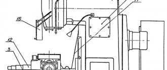
Lubrication system
The location of lubrication points is shown in Fig. 26. Table 5 contains a list of system elements and lubrication points.
Description of the lubrication system
Careful attention to lubrication and normal operation of lubrication systems are a guarantee of trouble-free operation of the machine and its durability.
The machine has two isolated centralized lubrication systems:
- gear wheels, gearbox bearings and gearbox elements;
- gears, feed box bearings, console, slides, console guides, slides and table.
The oil reservoir and gearbox lubrication pump are located in the frame. Oil is poured into the reservoir through cover 5 to the middle of oil indicator 9. If necessary, the oil level must be replenished. The oil is drained through pipe 6.
The operation of the gearbox lubrication system is monitored by oil indicator 7.
The oil reservoir and lubrication pump for the units that provide the feed movement are located in the console. Oil is poured into the reservoir through elbow 2 to the middle of oil indicator 1. It is not recommended to exceed this level: filling above the middle of the oil indicator can lead to oil leaks from the console and feed box. In addition, when the reservoir is overfilled, oil flows through the racks into the gearbox housing, which can lead to damage to the limit switch for short-term activation of the feed motor. When the oil level drops to the lower point of the oil indicator, the reservoir must be refilled. Oil is drained from the console through plug 3 at the bottom of the console on the left side. The operation of the lubrication system of the feed box and console is monitored by oil indicator 10.
The operation of the lubrication system is considered satisfactory if oil flows out of the supply tube in drops; the presence of a trickle or filling of the indicator niche with oil indicates good operation of the oil system.
The guides of the table, slide, console and longitudinal drive mechanisms located in the slide are periodically lubricated by a pump located in the console. The oil to lubricate these components comes from the console reservoir. The console guides are lubricated from button 11, and the guide slides, table and longitudinal drive mechanisms are lubricated from button 12.
The sufficiency of lubrication is assessed by the presence of oil on the guides.
Lubrication should be carried out taking into account the degree of loading of the machine, as a rule, before work (approximately twice a shift for a duration of 15-20 seconds.
The end support bearings (point 4) of the longitudinal feed screw are lubricated by extrusion.
Features of Numerical Control Machine
The basis of CNC horizontal milling machines is the same bed as on station wagons. They differ radically in the organization of the coordinate drive and the tool. The place of mechanical feed speed control elements is taken by high-torque servos, and optical encoders appear instead of dials. The main movement drive is replaced with a frequency-controlled one, which makes it possible to completely get rid of intermediate mechanisms between the motor and the spindle.
This design of the machine is dictated by the need to control the current position of all systems and mechanisms by the CNC rack. This data is entered into the computer's memory, and based on it, movement commands are issued.
The design of CNC machines has become simpler and more reliable due to the absence of a large number of mechanisms. Their functions have been transferred to software. Since unreliable gear transmissions have been replaced by direct drives, the processing speed and accuracy have increased, and it has become possible to simultaneously move a part in all coordinates with adjustable feed speed.
6M12P vertical cantilever milling machine with a rotating head. Video.
- Vertical cantilever milling machines 6Р12, 6Р12Б, 6Р13, 6Р13Б. Operating manual, 1977
- Cantilever milling machines 6Р82, 6Р82Г, 6Р83, 6Р83Г. Manual,
- Widely universal cantilever milling machines 6Р82Ш, 6Р83Ш. Operating manual 6Р82Ш.00.000 РЭ. Part 1, 1984
- Avrutin S.V. Fundamentals of Milling, 1962
- Avrutin S.V. Milling, 1963
- Acherkan N.S. Metal-cutting machines, Volume 1, 1965
- Barbashov F.A. Milling 1973
- Barbashov F.A. Milling work (Vocational education), 1986
- Blumberg V.A. Milling machine handbook, 1984
- Grigoriev S.P. Practice of coordinate boring and milling work, 1980
- Kopylov R.B. Working on milling machines, 1971
- Kosovsky V.L. Handbook of a young milling operator, 1992
- Kuvshinsky V.V. Milling, 1977
- Nichkov A.G. Milling machines (Machinist's Library), 1977
- Pikus M.Yu. A mechanic's guide to repairing metal-cutting machines, 1987
- Plotitsyn V.G. Calculations of settings and adjustments of milling machines, 1969
- Plotitsyn V.G. Setting up milling machines, 1975
- Ryabov S.A. Modern milling machines and their equipment, 2006
- Skhirtladze A.G., Novikov V.Yu. Technological equipment for machine-building industries, 1980
- Tepinkichiev V.K. Metal cutting machines, 1973
- Chernov N.N. Metal cutting machines, 1988
- Frenkel S.Sh. Handbook of a young milling operator (3rd ed.) (Vocational education), 1978
Bibliography:
Related Links. Additional Information
- Milling machines: general information, classification, designation
- Comparative characteristics of cantilever milling machines of the 6N, 6M, 6R, 6T
- Feed box for console milling machines of the 6M : 6M12P, 6M13P, 6M82, 6M83, 6M82Sh, 6M83Sh
- Feed box for console milling machines of the 6P : 6P12, 6P13, 6P82, 6P83, 6P82Sh, 6P83Sh
- Feed box for console milling machines 6T : 6T12, 6T13, 6T82, 6T83, 6T82Sh, 6T83Sh
- Milling machine repair technology
- Adjustment of milling machines
- Friction clutch. Friction shaft. Friction clutches in metal-cutting machines
- Automatic cycles of milling machines (6P12)
- Testing and checking metal-cutting machines for accuracy
- Directory of universal milling machines
- Manufacturers of metal-cutting machines in Russia
- Manufacturers of milling machines in Russia
- Electrical equipment of milling machines 6T12, 6T13, 6T82, 6T82G, 6T82Sh, 6T83, 6T83G, 6T83Sh
- Electrical equipment of milling machines 6P12, 6P13, 6Р82, 6Р82Г, 6Р82Ш, 6Р83, 6Р83Г, 6Р83Ш, 6Р12Б, 6Р13Б
- Electrical equipment of milling machines 6M12P, 6M12PB, 6M13P, 6M13PB, 6M82, 6M82Sh, 6M82GB, 6M83, 6M83Sh
- Electrical equipment of milling machines 6T10, 6T80, 6T80G, 6T80Sh
- Electrical equipment of milling machines 6Р10, 6Р80, 6Р80Г, 6Р80Ш
- Electrical equipment of milling machines 6N10, 6N80, 6N80G, 6N80Sh