How to make a homemade support for a lathe with your own hands?
In metal work, a lathe is used to produce cylindrical (conical) shaped parts.
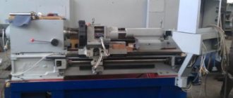
There are many models of this production device, and all of them have almost the same layout of similar components and parts. One of these is the machine support. Homemade lathe
To better understand the functions performed by a lathe support, you can consider its operation using the example of the common 16k20 model. After reading this information, perhaps some home craftsmen will have the idea to create a homemade lathe for metal work with their own hands.
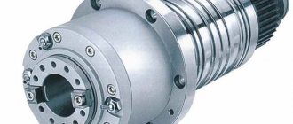
Spindle as an element of a lathe
The most important structural component of a lathe is its spindle, which is a hollow metal shaft with a conical inner hole. What is noteworthy is that several structural elements of the machine are responsible for the correct functioning of this unit. It is in the inner conical hole of the spindle that various tools, mandrels and other devices are fixed.
Spindle drawing of screw-cutting lathe 16K20
In order to be able to install a faceplate or a lathe chuck on the spindle, its design includes a thread, and to center the latter there is also a collar on the neck. In addition, to prevent spontaneous unscrewing of the chuck when the spindle is quickly stopped, some models of lathes are equipped with a special groove.
The results of machining parts made of metal and other materials on the machine largely depend on the quality of manufacturing and assembly of all elements of the spindle assembly. In the elements of this unit, in which both the workpiece and the tool can be fixed, there should not be even the slightest play that causes vibration during the rotational movement. This must be carefully monitored both during the operation of the unit and when purchasing it.
In spindle units, which can be immediately determined from their drawing, sliding or rolling bearings can be installed - with roller or ball elements. Of course, rolling bearings provide greater rigidity and accuracy; they are installed on devices that process workpieces at high speeds and with significant loads.
Şərh • 40
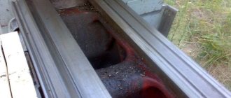
Maybe it’s worth turning it over so that the chips don’t get stuffed inside
a lot of letters, and a lot of fingers))) “friend-friend” - “brother-brother”)))
What happened as a result. Can I have a video of how the machine sharpens?
There are plenty of them, look for them on my channel
Not only collective farms. State farms too, everything will be fine, everything will be fine, everything will be fine, I know, I know, I know, I know, I know, I know, I know, I know, I know, I know, I know, I know, I know, I know, I know, I know, I know, I know, I know. I know I know I know I know I know I know I know I know I know
Work worthy of respect. I wish you success and health.
In my case, on the rods of the shock absorber, 20mm on a cut, how did you do it?
+Vladyk Naz just bought a channel for the bed today. There is a video, I'll start collecting it
What did you use to cut the plate out of the slab? Somehow too smooth for a simple grinder.
I also made a dovetail from a corner, vibration appeared almost immediately. As I understand it, plain metal is still not suitable for the loads of a lathe. My advice is, you shouldn’t waste money, effort and nerves on a homemade lathe, no matter how much you would like to make it yourself. It's better to buy a factory one. This is my personal experience. and I wish you good luck
so that the metal does not move when welding long seams, the seam must be welded in a REVERSE STEP method “weld a few cm, step back a few cm and weld back to the welded seam, etc.
Alim, where is the continuation? I want to see what happens. I did it on shock absorber struts, so at 200 rpm it crushes on blanks over 30 mm. It jumps like on springs. I'm thinking about how to make the tails.
car shock absorbers, the rod itself is used.
What kind of shock absorbers are they from?
Kirill Gaidukovich there is no continuation yet unfortunately
idea 5 execution 2 as they say. Very flimsy, especially the base of the flipper and tail. on steel he will vomit immediately.
Yuriy Klevchuk won’t throw up right away, but if something happens we’ll strengthen it. I am making a machine for myself, I will not make money from it. Everything will get stronger along the way, work will show
and if you add clamping bolts through a powerful spring, vibrations will be dampened. but you will have to make more passes.
An interesting approach to the solution. ) But I would do one more thing: 1. I would place a sanded strip(s) (for example, from wood planing knives) between the moving part and the fixed part and tighten them with bolts (with a lock nut) - to reduce friction forces, to remove gaps and make it easier installation work 2. Transverse welded ribs on inclined fixed plates (dovetail) - so that the plates do not bend. 3. I would definitely install the dial on the transverse screw - practice shows that without it it’s difficult to make anything more precise than a millimeter (if you don’t use additional stops, of course.) I wish you good luck!
Electrical part of a lathe
All modern lathes and screw-cutting lathes for metal, which are characterized by a fairly high complexity of their design, are driven by a drive, which uses electric motors of various powers. Electric motors installed on such units can be asynchronous or powered by direct current. Depending on the model, the engine can produce one or more rotation speeds.
Electrical diagram of a 1K62 lathe (click to enlarge)
Most models of modern metal lathes are equipped with squirrel-cage motors. To transmit torque from the engine to the elements of the machine's gearbox, a belt drive or direct connection to its shaft can be used.
On the modern market there are also models of lathes in which the spindle rotation speed is controlled in a stepless manner using electric motors with independent excitation. The shaft rotation speed of such a motor can be adjusted in the range of 10 to 1. However, due to their large dimensions and not very economical electricity consumption, such electric motors are used extremely rarely.
Two-speed motor with flat belt pulley
As mentioned above, electric motors operating on direct current can also be used to drive lathes. It is these electric motors, characterized by large dimensions, that provide a stepless change in the speed of rotation of their output shaft.
The electric motor is the main part of the electrical system of any lathe, but it also includes a lot of additional elements. All of them, functioning in a complex, provide ease of control of the machine, as well as the efficiency and quality of the technological operations that are performed on it.
Screw-cutting lathes are multifunctional metalworking equipment capable of performing a whole range of technological operations, including turning, boring, end processing, countersinking, reaming and trimming.
This article discusses the design, functional purpose, operating principle and capabilities of lathe group machines. We will study the market for the most common models and get acquainted with their technical characteristics.
What tasks can a home machine perform?
Before making a mini metal lathe with your own hands, you need to carefully understand the functions of the future unit.
Can he do what a person needs in the first place? After all, not everyone can work with metal, which cannot be said, for example, about such a material as wood.
In general, the list of available works is as follows:
- Processing parts with a round cross-section (for example, wheels, round furniture parts, handles for construction tools, etc.);
- Precision processing of ends and grooves;
- Using the countersinking process, that is, enlarging existing holes (for example, in order to screw in a screw of a larger configuration, etc.);
- Trimming parts to required sizes;
- Creating a relief surface (using the rolling technique);
- Creating internal and external threads on parts.
What can we say in general? It is perhaps worth mentioning the fact that purchasing a serial lathe, which, by the way, is a rather impressive piece of equipment, is not entirely advisable.
And it is extremely difficult for a beginner to use it. Therefore, assembling such a unit on your own is the best choice, especially since with the right approach it will be able to process metal, wood, and even plastic.
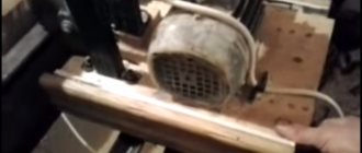
How to choose a motor for a homemade metal machine
The most important part of a lathe, photos and videos of the assembly of which can be found on the Internet, is considered to be an electric motor .
With its help, the working part of the product moves. Thus, the maximum power of the machine depends on the power of this part. This indicator must be selected depending on the dimensions of the iron blanks that will be processed in the future. When you need to process small workpieces on a lathe, an electric motor with a maximum power of up to 1.4 kilowatts, which can be taken from a simple sewing machine or other electrical device, is sufficient. To work with large workpieces, you need an electric motor with a power of up to 2 kilowatts.
How is it built?
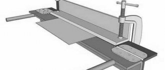
The caliper design consists of the following mechanisms:
The longitudinal support is a slide (lower slide) on which all the mechanisms of the unit are mounted. Drive from a lead shaft or lead screw, through switching devices located in the apron, as well as manually. The lower slide of the caliper moves the entire unit along the bed guides.
The transverse support is a mechanism coupled with the guides of the longitudinal support. Drive: mechanical - from a carriage screw or manually. Sets the direction of the rotary plate and the upper support with the tool holder.
The rotating plate is secured with a nut on the cross slide. The mechanism of the upper slide (upper support) is installed on the rotary plate.
The upper support is a carriage with a slide (upper slide) connected to the guides of the rotary plate. The rotary plate is designed to install the upper support at an angle to the axis of the cross slide (cutting cones).
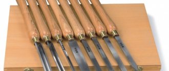
Cutting head (tool holder) is a movable mechanism installed on a horizontal platform of the upper slide with four platforms for fastening a cutting tool or processing units (for example, a grinding head) or devices for fastening the workpiece itself.
The apron is the main control unit for the entire operation of the caliper. On it are mounted the switching and switching controls of the machine mechanisms, which directly communicate the feed amount to the cutting tool.
Caliper mechanisms provide the cutting tool with movement in the horizontal plane:
Machines weighing more than 1000 kg are equipped with devices for accelerated movement of the support. Lightweight machines, as a rule, do not have such devices, but craftsmen successfully solve this problem on their own.
Headstock
The parts located in the headstock serve to support and rotate the workpiece during processing. There are also units here that regulate the speed of rotation of the part. These include:
The headstock is separate from the machine
The main part of the headstock in a lathe is the spindle. On its right side, facing the tailstock, there is a thread. Chucks that hold the workpiece are attached to it. The spindle itself is mounted on two bearings. The accuracy of the work performed on the machine depends on the condition of the spindle assembly.
Gearbox top view
In the headstock there is a guitar of interchangeable gears, which is designed to transmit rotation and torque from the output shaft of the gearbox to the feedbox shaft for cutting various threads. Adjustment of the caliper feed is carried out by selecting and rearranging various gears.
Guitar of replacement gears of an Optimum lathe Guitar of a Soviet metal lathe Maintenance