Functional purpose and device
As previously noted, a ball screw is used to transmit force and convert rotation into translational motion. The device is characterized by the presence of several elements:
- Rod with helical grooves.
- Nut with suitable thread and size.
The most widely used versions are those characterized by threads with a semicircular profile. Ball screws are quite simple in design, which determines their reliability and long service life.
Ball screw device
Ball screw application
Ball screws are used in various equipment that require converting the rotation of the drive into translational motion of a certain unit. They are in demand in the metallurgical sector, mechanical engineering, the automotive industry, aircraft manufacturing, rocketry, the food industry and light industry.
Based on such elements, linear ball screw modules are created containing a metal housing, measuring components, servo drives and automatic control devices. They are used to equip CNC machines and 3D laser printers. High demands are placed on the quality of these components, because the processing speed, smoothness of operation, equipment operating efficiency, positioning accuracy and repeatability of operations depend on them.
Principle of operation
The screw pair is characterized by a fairly simple design, which works as follows
- As the nut rotates, the balls roll along the created channels.
- The balls are capable of progressively moving the nut, pushing it out of the thread. In this case, there is a bypass channel, due to which the balls return to their original position.
- The ball moves along a closed contour, which is located inside the nut.
- The most widespread variants are ball screw gears, in which the return channel connects two adjacent turns.
There are a variety of options for the design in question. They are selected depending on operating conditions and purpose. An example is that in machine tool construction a ball screw with a three-circuit nut is used. For this purpose, a special liner is created, for which an oval-shaped window is created. To reduce friction and increase efficiency, three liners are used at once, placed at an angle of 120 degrees relative to each other.
Ball screw diagram
Ball screw maintenance, preload adjustment
The ball screw is a popular and useful design solution. Compact, reliable design, used wherever precision movement of actuators is required. For example, moving a milling machine table along three coordinates. But over time, the screw-nut pair wears out, axial and radial play and even wedging appear. As a result, the quality of the processed surface suffers: both geometry and roughness. For maintenance and adjustment of the ball screw, it must be disassembled and then reassembled, controlling the preload, i.e. clearance between rolling elements, nut and screw. This is not at all easy to do, but if you know the intricacies, anyone can do it.
Disassembly
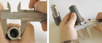
One of the reasons for the unsatisfactory performance of ball screws is poor quality assembly by the manufacturer. This applies to ball screws made in China. You need to check the build quality immediately after purchase, without installing the ball screw on the machine. To do this, you need to remove the dust rings installed on each side of the nut and try to move a row of balls in the outer contours of the nut. A gap should appear as wide as the diameter of one ball. This is how it should be for the ball screw to work properly. But sometimes there are simply not enough balls (there is room in the circuit for 2 more balls), which will lead to very rapid wear of the ball screw. To check or service the internal ball circuit, the nut must be removed. This is done by simply twisting to the nearest end of the screw. The balls should not fall out; they are held inside the grooves by the lubricant. You can remove them using tweezers of a suitable size.
Flushing, lubrication, preload adjustment
Now the nut needs to be washed to remove small chips and wear products. Using a syringe, generously apply a lubricant such as lithol, cyatim 201, onto the surface of the grooves. If the reason for servicing the ball screw is backlash, and the nut design is one-piece, you need to select balls with a diameter one size larger in the manufacturer’s ball size range. Important: the balls must be from the same package (same series). If the nut is assembled, select (reduce) the thickness of the adjusting ring between the nut halves.
Assembly
Place the balls into the grooves with tweezers, starting from the middle (inner) contour, until the contour is closed and remove the last ball. Place the balls in the outermost contours using the same principle. Insert a plastic sleeve-device into the nut (usually included with the nut). The purpose of the bushing is to hold the balls in the grooves as the screw moves inside the nut. If you don’t have a bushing, you can make it yourself on a lathe; it’s a simple part. Place the screw and start screwing it into the nut. As the screw moves, it will push the sleeve out of the nut. If you feel resistance or wedging when moving the screw, you need to roll it back and continue screwing again. When finished, check the preload. If everything is satisfactory, install the dust protection rings of the nut in place.
High-speed or high-speed ball screws
Modern machines and other equipment are characterized by high productivity and versatility in use. As a rule, the force is created by a motor that makes a rotational movement. In order to convert rotation into reciprocating motion, a screw gear is used. The conventional screw and nut combination is less efficient than newer high-speed designs.
The high-speed ball screw has the following features:
- In production, a material is used that is characterized by high wear resistance. Too much wear results in loss of accuracy.
- A special ball screw drive ensures fast movement of the nut.
Most often, high-speed ball screws are installed on CNC machines. Their use ensures rapid movement of the executive bodies.
What is a ball screw?
A ball screw, abbreviated as ballscrew, is a functional mechanism that converts rotation into linear translational motion.
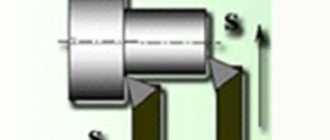
Structurally, it consists of a long screw and a ball nut moving along it. There are balls between their threaded surfaces. They move along a trajectory in the shape of a spiral, after which they return to their original position through the channels of the nut thread and the raceways of the screw. Most often, the ends of the screw are fixed on bearing supports, and a nut is connected to the moving unit. When the propeller rotates, it moves linearly along it together with the payload. But there are also ball screws of a different design - with a rotating nut. In such models, the screw moves progressively relative to the nut.
Classification
A variety of technologies can be used in the manufacture of ball screws. Depending on their features, the following types of structures are distinguished:
- Rolled ones are obtained by applying the cold rolling method. As a rule, such technology is characterized by lower costs when using it. Due to this, the price-quality ratio is as high as possible, but the accuracy of the resulting products is low.
- Ground – precision products that are ground after threading and hardening. This ensures a high degree of smoothness. Most products from this group are characterized by increased accuracy. However, the process of hardening and grinding determines a significant increase in the cost of the product.
Types of Ball Screw
- The classification can also be carried out according to design features:
- When manufacturing standard ball screws, DIN standards are used.
- Precision ones are obtained by using grinding technology. The design may consist of one or two nuts that are pre-tensioned.
- There are versions obtained by grinding, with a separator. This design is characterized by the presence of a structure that ensures the return of the balls to their initial position.
- The ball screw drive with a rotating nut has a built-in bearing that ensures precise movement of the moving element.
- This category also includes a splined shaft with ball-type bushings. This ball screw design is compact and easy to install.
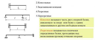
- Console type version. Used when compact transmission is required.
This classification is taken into account when choosing the required design.
Ball screw technical characteristics
When choosing a ball screw, its main characteristics are taken into account. As a rule, they are as follows:
- Length of the rod. The characteristics of ball screws for CNC equipment are characterized by a maximum length of about 2 meters. This is due to the fact that a product that is too long can become deformed when subjected to a single point impact.
- Linear speed movement is the main indicator that is worth considering.
- The diameter and pitch of the screw can also be called important indicators. They determine what kind of load can be applied.
- The accuracy of the product, which varies from C1 to C10.
Ball screw technical characteristics
You can also find tabular information that is used to determine the main characteristics.
Gear Setting
The selection of ball screws can be carried out in the process of analyzing the structure and preliminary design. Before installing the rack and pinion ball gear, the following calculations are carried out:
- Table stroke values.
- The required force that should be on the screw.
- The most suitable screw length is selected.
- Accuracy determines whether a ground or cold rolled ball screw needs to be installed.
- The design features of the nut are determined: the return of the balls to their original position, whether a bearing is needed, what the nut should be like. An example is that a design with a single nut is much cheaper, but the double nut version is more wear-resistant.
- It is clarified whether the free end should be securely fixed.
- How the ball screw connects to the housing is determined.
Ball screw before installation
After selecting the appropriate ball screw design, its installation is carried out. Fastening can be done using screws and rivets or by welding.
Application area
The main characteristics determine the widespread use of ball screws. An example is various components of automobiles and machine tools. More obvious applications of ball screws include the following cases:
- Manufacturing of CNC machine drives. Modern versions have several linear drives. An example is the case where the Tornos machine has 14 controlled axes.
- KAMAZ and some other automakers use a similar rack in the manufacture of the steering mechanism. This simplifies the process of changing the position of heavy wheels that are burdened with dirt.
- During the production of printers and other printing equipment, a similar rail is installed.
Ball screw on CNC machine
As previously noted, the engine is installed as the main source of force. The rotation is converted by the rack into a reciprocating motion, which is quite common.
Advantages of ball screws over other types of gears
Ball screws have quite a lot of advantages. This design is characterized by the following advantages:
- Low coefficient of friction, which is achieved through the use of balls.
- Higher efficiency value. If we compare other analogues that can transmit translational motion, they are significantly inferior. For many versions, the ball screw has an efficiency rate of 90%.
- There is no sliding due to the use of grooves with balls. This also significantly increases the service life.
- Ease of maintenance and repair. If necessary, you can quickly add oil to the propeller travel area. The lubricant is evenly distributed over the surface, thereby increasing the service life.
- High speed of movement, which can be achieved through the use of special versions of ball screws.
- Reduced power requirements for the drive. This is due to the low resistance of the propeller.
However, there are several significant disadvantages that must be taken into account when choosing a drive. An example is the high probability of reverse motion when installing a screw at a large angle or vertically. This disadvantage is due to the fact that friction is minimal.
The ball screw in question is not recommended for use when creating manual feeds. In addition, the high cost of the product can be considered a negative factor, since it consists of several precise elements. To ensure a low degree of wear, the surface is hardened, which also increases the cost of the product.
Ball screw selection. The most important parameters.
In today’s article we will look at such a typical machine tool assembly as a ball screw (an abbreviated name from the words: ball screw, ball screw, ball screw drive, or also from the common spelling variations “ball screw”, “ball screw”, etc. ). This, often irreplaceable, element is quite ordinary for a design engineer with experience in machine tool design, but very extraordinary for those who encountered it for the first time. We will look at ball screws from the perspective of a person who does not have a special education in this field, but wants to assemble a CNC machine for himself or maybe for commercial purposes. We will not describe the general principles of operation, describe and sketch how the balls roll in the nut, what shape these same nuts come in - you can easily find all this information on the Internet. Let's consider the ball screw parameters that directly affect the quality characteristics of the machine: speed, accuracy, load capacity.
It is difficult to highlight the main thing, so let’s imagine ourselves in the role of a buyer who wants to purchase such an important part that determines a significant part of the technical characteristics of the machine - a ball screw. After a quick look at a lot of sites, we learn that the determining parameters are the diameter and pitch of this very ball screw. From any of the sellers we will find: a 16x5 ball screw (for example) - the length is such and such, the type of nut and... And everything seems to be clear, but is it so simple? Why do these experienced engineers look so serious when choosing a ball screw? And are sellers really honest with us, focusing only on these parameters? The drawing of a conventional ball screw will make you think about this. By the way, it is clickable (PDF format, 105 kB).
In the future, we will provide only fragments to make it easier to read and so that each time we do not end up with a full-size PDF document. This is a standard drawing with a lot of standardized parameters, according to which real production is carried out. It is important to note that the parameters of the nut and screw are closely related and inextricably linked. That is, by replacing the nut with another, seemingly “same screw”, you will already get slightly different - but seemingly “same” characteristics. If you purchase a product with parameters not specified in the illustration, or a separate nut and screw, think about whether you bought this for a machine or do you need a screw jack? There is a screw here and there.
There is probably no point in describing geometric parameters and tolerances. Everyone at school had drawing, and compensating for gaps in basic education is not the purpose of this article, so let’s look directly at the characteristics (technical data) indicated in the tabular section. With the exception of one small icon - a half-filled circle.
This is a transitional vacation zone. The raceways in this zone have lower hardness compared to the rest of the hardened part. And this is the limit beyond which it is not recommended to overdrive the nut during operation. The presence of this part is due to technological processes during processing of ball screws for the bearing assembly. The length of this part is variable and depends both on the diameter of the screw and on the tempering scheme used. All you need to remember is that this is the end point of the path for the end of the nut.
Next, in order, let's start directly with the notation.
4 – number of screw passes. For the consumer, this information does not properly convey anything. One can, of course, argue that this increases the maintainability of the ball screw later in relation to, for example, the 2nd starts of the screw, since it allows you to install a new nut on new (unused) raceways, but, firstly, this depends on the design features of the nut, and secondly, as noted earlier, it is not easy to comply with the characteristics of the screw-nut when installing a new one, although it is possible if you initially had a complete drawing. To summarize, this parameter (the number of propeller passes) is rather informational.
R - speaks of right-hand thread. By the way, the left-hand one is not used often, and mainly where it is necessary to ensure synchronous convergence and divergence of the mechanism without significantly complicating the kinematics.
20 – screw size. A value often taken as the outer diameter of the screw, but not always 100% corresponding to it, especially in rolling screws. The differences between the actual size are usually small from the overall size, but can be critical in precise mechanisms - please pay attention.
20K3 - values related to the nut indicating the overall size of the screw (20) for which it is intended, the recirculation scheme of the rolling elements and the number of circulating circuits (K3). Again, the values for the end user are not very interesting, but nevertheless they determine some technical parameters. In particular, the maximum possible speed of rotation of the propeller, indirectly load characteristics, as well as noise.
FSCNW – the nut itself with a seal. In this case, FSC: flanged, single with cassette type of recirculation. NW – synthetic rubber seal. It is worth noting that a very common type of seal is fluoroplastic, but it can be called a seal at a stretch, since it does not provide a tight fit to the screw profile and, accordingly, the necessary sealing of the inside of the nut. Considering the fact that one of the most common reasons for nut failure is clogging of the recirculation channels and their subsequent squeezing out by balls, it makes sense when choosing a ball screw to pay close attention to the seal.
2380 – length of the screw part.
2500 – total length of the screw.
0.05 – indicates the accumulated error per 300 mm of the length of the screw part. Those. These numbers directly characterize the accuracy. In this case, the deviation can be up to 50 microns for every 300mm of stroke.
More detailed information on the types of nuts, screws, their types and design features can be found in the manufacturers' catalogs, which are usually freely available.
Now to the tabular part. Let's look at it in parts.
As you can see, some lines are empty. This is data provided by the client during the production of ball screws for specific design requirements. In our case, there were no special requirements for the ball screw.
Support method – fixed-fixed. Indicates the mounting pattern of ball screws in bearing supports - two fixed ones.
Critical speed – maximum permissible rotation speed. From this value we can easily calculate the maximum linear speed of the nut by multiplying it by the pitch of the screw. In our case, 668x20 = 13,360 mm/min. It is important to know that this value depends on the diameter of the screw, its length and the fixation pattern in the bearings. If you change the type of bearing support on one side, the permissible speed will be different.
V300p – accumulated error per 300 mm screw length. In our case, this is 0.05 mm - the most typical value for general purpose machines. In practice, this means that the deviation over a 300 mm screw length will not exceed 50 microns. This may seem like a lot, but this is a deviation from the ABSOLUTE value at 20ᴼС ±1ᴼС! Those. for example, instead of the specified 300 mm, in reality, the machine axis can travel 300.05 mm. How critical this will be is up to you to decide. You can always buy a ball screw with a higher accuracy class. But is this really necessary? High accuracy also implies high accuracy of the remaining elements of the system, including the machine base itself. We’ll leave discussions on how to create an ultra-precision machine for later, but as for typical applications, in our opinion, this class of ball screw accuracy is more than enough. In our projects we use this exact accuracy class.
ep is the maximum total error of the screw over its entire length. Essentially, this is a calculated value equal to the length of the screw part divided by 300 and multiplied by V300p. It is more of an informational nature for a specific screw. The rest of the part indicates the general accuracy standards (normal tolerance) for dimensions whose tolerances are not indicated in the drawing.
Let's move on to the most informative tabular part.
For convenience, we present the geometric parameters of the screw indicated in the table in the form of a single illustration with symbols indicated in English and Russian.
Only one value in this figure requires explanation - root diameter (RD) - this is the internal, also called root, diameter of the screw. This value is needed to calculate the critical rotation speed. Often the critical speed is calculated by the outer diameter of the screw, which is not entirely correct.
Preload – preload. A value indicating the equivalent load applied to the ball screw nut. The larger it is, the higher the rigidity of the screw-nut pair. The very presence of this parameter indicates that the system is backlash-free. Those. the nut does not have free play. This is extremely important for machines built using linear guides. Despite the fact that even hobby CNC systems make it possible to take into account the backlash of the mechanical system in order to compensate for it, this does not work as well as we would like, or rather, does not work at all. The reason for this is the movement of the mechanism through the working tool (milling cutter, for example) during processing of the part. It's funny that CNC backlash compensation can work quite well in systems built on dovetail slideways. Again, we won’t delve into the theory of why this happens, it’s just worth remembering that in machines on rolling guides, the screws must be preloaded. Preload itself is not a free thing, because... to ensure it, it is necessary to maintain high precision parameters for the screw-nut pair, and even more so to normalize it within specified limits, as in our case - 40 kg. It would seem, why ration? We take it with reserve! However, it's not that simple. An increase in preload leads to a reduction in the service life of the ball screw, because as we remember, this is the equivalent of the applied load, which means that even without load from the mechanism, the ball screw is already working with a load. Additionally, the torque required even for idle rotation of the propeller also increases, which will lead to an increase in drive power. Based on many years of accumulated experience, for general industrial use we consider the most optimal choice of interference to be 4-5% relative to the dynamic load capacity of the ball screw (as in our case). In systems with shock and severe vibration loads, preload should be selected in the range of 7-10%. Well, for systems that require special smoothness - no more than 2%. What is described above does not mean at all that ball screws with a gap do not have the right to life. There are many mechanisms where a gap within reasonable limits will not affect the result of the work at all, but in the version of constructing the machine that we were given earlier, the gap is not acceptable.
SF (starting force) – the force of starting the nut (without load). It is measured with a dynamometer tangentially to the circumference of the nut when pulling on one of the mounting holes. Expressed in kilograms of force. If the shape of the nut is different from round - for example, square, then the load application point is additionally indicated in the drawing.
DRAG TORQUE - just like starting force, indicates the force required to pull out (start movement) the nut without load, only expressed in kilograms of force per centimeter. A value more convenient for use in the calculation part than SF. These values are easily converted into each other, so even if one of them is indicated, this can be considered sufficient.
DIRECTION OF TURN - indicates the direction of the propeller entry. In our case, “R” is right-handed.
BACKLASH - Indicates end play. We have “0”, which means a system with preload.
CIRCUIT – number of ball coils carrying the load.
LEAD ANGLE – angle of elevation of the helical groove.
DYNAMIC (kgf) – dynamic load capacity of the propeller in kilograms of force. The value, when applied, the life of the screw will be 1,000,000 revolutions (with 90% probability). This value is important purely for the calculation part and is not recommended. The recommended operational load on the propeller is 20-25% of the dynamic load. In this case, the estimated resource will be 64 - 125 million revolutions (again with a 90% probability). However, depending on the specific operating conditions, the designer can use other values of applied loads.
STATIC (kgf) – static load capacity of the propeller in kilograms of force. The force at which the permanent deformation between the ball and the raceway will be 0.0001x the diameter of the ball. As you yourself understand, it is not worth loading the ball screw to this value, even for a short time.
The final part of the table contains information about the materials, the hardness of the raceways, who drew, who checked... The undoubted benefit that you can get from this table is the name of the customer in the CUSTR column, in this drawing - KUGEL (Kyugel). This is the name of the client who placed an order with the manufacturer’s plant and, accordingly, if you buy a ball screw from our company, then there is only one link between you and the manufacturer, and it is official, which allows you to have no doubt about the quality of the purchased product. You can buy ball screws at a competitive price in the relevant sections of our online store:
Ground ball screws
Rolling ball screws
Ball screws for repair needs (for the most common machine models)
Articles
09 Nov 2020