This article describes the technology for repairing the spindle of a 16K20 .
The spindle is an expensive and difficult part to manufacture, so it should be changed only in exceptional cases, especially on large machines. On spindles, journals, end holes, places for ball and roller bearings, threads and keyways wear out more often.
Spindle journals . The wear of the journals largely depends on their quality. If the journals are damp, then the wear can be very significant and large scuffs around the circumference are possible. If the spindle design allows, the journal should be sharpened, ground and polished with GOI paste or presses with fine emery cloth, while generously moistening the journals with oil. If there are no grinding machines, then the journals should be cleanly processed with a wide spring cutter on a lathe, removing very thin chips, and then polished to a mirror finish.
If it is not possible to reduce the diameter of the journal, you can machine it and fit a bushing made of the appropriate steel onto it with a shrink fit. If this is not possible, then the spindle must be replaced with a new one.
With hardened or nitrided journals, deep scuffing does not occur. Usually there are risks and uniform or uneven wear. In these cases, the journals need to be ground and polished to a mirror finish, but before polishing it is necessary to check whether the hard layer has been removed in whole or in parts. The test can be carried out by puncture with a small file. If the neck is soft, it should be chrome-plated with a thin layer (up to 0.01-0.03 mm of chromium). If the spindle steel can be hardened, the journals can be hardened with high frequency currents. If it is impossible to increase the hardness of the journals, the issue of replacing the spindle must be decided depending on the operating conditions of the machine.
Due to the negligence of workers, the spindle taper This also occurs from turning the tool shank or mandrel. You can check the correctness of the cone by caliber. To do this, you need to first clean the cone from nicks and sand it with an emery cloth, and then wipe it well, apply three or four chalk lines to the gauge along the cone forming lines, insert the gauge into the spindle cone and carefully turn it several times. By the way the chalk lines on the caliber are erased, one can judge the correct shape of the spindle cone.
If the cone needs to be ground, then it is best to do this on the machine itself with a portable grinding device or, in extreme cases, with a scraper manually according to the caliber. If you need to bore the cone, it is better to bore it for the adapter sleeve, whose internal cone is made standard so that it is suitable for normal centers and mandrels.
Lathe spindle 16K20. Lathe spindle repair
The spindle is one of the critical parts of the machine, the accuracy and rigidity of which determines the quality of the operations performed on the machine. Deviations from the shape and dimensions of the spindle surfaces are allowed within a very narrow range, therefore increased requirements are placed on the repair of spindles. The specifics of repairing the ends of spindles that have a conical hole and thread, a landing journal or a cone for mounting technological equipment have been determined. If during repairs the dimensions of the surfaces of the spindle end are changed, then the technological equipment supplied with the machine will need to be changed or altered. Therefore, during repairs, they strive to restore it to its original dimensions, especially for the surfaces of the spindle ends.
The choice of method for restoring the main surfaces of the spindle is made depending on the amount of wear.
When the spindle surfaces are worn down to 0.05 mm per side, preliminary grinding is first performed to restore the geometric shape of the surfaces and chrome plating, after which they are finally ground, removing a layer up to 0.03 mm per side.
The surfaces of the spindles, which have wear of more than 0.05 mm per side, are subjected to metal build-up using one of the known methods, and then to mechanical processing.
During restoration, the conical hole at the end of the spindle is usually ground, then the end of the spindle is trimmed to a conical gauge. The end of the spindle flange is also trimmed after restoration by grinding the conical journal at the end of the spindle.
During repairs, the threads of spindles are usually cut to a full profile, and non-standard nuts for them are made anew.
When restoring spindles, it is necessary to choose repair methods that, in parallel with restoring the original dimensions, would ensure an increase in the wear resistance of the surfaces.
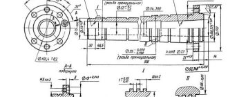
A repair drawing of a lathe spindle is shown in Fig. 27. In table. 14 shows the technological route for repairing the spindle.
Manufacturing of spindles
The spindle of a metal-cutting machine is structurally a multi-stage shaft, in most cases hollow. The outer surface of the spindle consists of cylindrical, conical, threaded and splined sections, flanges, collars, keyways, grooves, holes and similar elements.
Cylindrical and conical surfaces act as support journals for bearings in which the spindle rotates. Pulleys, gears, couplings and other parts and assembly units are mounted on cylindrical, conical and splined sections. Flanges are used to accommodate technological equipment (for example, chucks). Burts, threads, mounting holes, grooves of various types and purposes are used to orient and secure parts and assembly units mounted on the outer surface of the spindle in a strictly defined position.
The internal cavity of the hollow spindle consists of a conical or cylindrical section with support flanges for installing chucks or mandrels or other technological equipment; cylindrical, threaded sections, grooves, ledges used for installing and securing parts of the clamp drive and control of chucks, mandrels, etc.
The spindle , together with the parts mounted on it (spindle assembly), largely determines the accuracy of the products processed on the machine. Technological requirements for the accuracy of the spindle assembly are established based on the conditions of its operation and purpose. Particularly high demands are placed on the stability of the position of the spindle rotation axis, and therefore on the correctness of the geometric shape of the journals (supports) and their relative position (alignment), as well as on the perpendicularity of the base ends to the spindle rotation axis; to the correctness of the geometric shape of the conical hole or cylindrical belt centering the chucks, mandrels and their alignment with the supporting (base) journals of the spindle.
According to manufacturing accuracy spindles , like machine tools, are divided into five groups: H, P, B, A, C. Tolerances for the shape of the spindle journals (ovality and taper) should not exceed:
- for spindles of normal accuracy (N) - 50% tolerance of the diametric dimensions of the journals;
- for spindles of increased (P) accuracy - 25% tolerance;
- for precision spindles (B, A, C) - 5-10% tolerance.
Deviations from the roundness of the support journals, depending on their size and the accuracy group of the machine, range from 0.3 to 4.0 microns. The permissible taper is 1.25-1.5 microns over a length of 300 mm. The end runout of the supporting flanges relative to the axis of rotation is 0.002–0.008 mm. The alignment tolerance of the threads and bearing journals must be within 0.025 mm.
The surface roughness of the bearing journals is Ra = 0.32 ... 0.04 µm, for mounting surfaces for cartridges, mandrels Ra = 0.63 ... 0.04 µm.
Depending on the purpose and production volume, forgings, steel castings, rods, pipes, cut products, and cast iron are used as blanks for spindles. for the manufacture of spindles : nitriding, case-hardening and hardening steels, gray high-strength and modified cast iron.
Ensuring high requirements for the accuracy of external and internal surfaces and their relative position is achieved through the correct design of the technological process and the use of high-precision finishing equipment.
A typical technological process for manufacturing spindles involves the following steps:
- production of blanks;
- preliminary turning of external surfaces based on center holes;
- pre-processing of the central hole, small and mounting holes in the flanges;
- finishing turning of external surfaces finally and for grinding, based on the center holes of the plugs, and with long spindles - along one of the central journals (in the rest);
- processing of spline and key surfaces, turning of the least precise external threads;
- heat treatment;
- grinding of external surfaces - cylindrical, threaded, end surfaces based on the center holes of the plugs and, if necessary, along the neck:
- grinding of internal surfaces based on bearing journals.
For particularly precise spindles, alternating stages of grinding and turning of external and internal surfaces are repeated twice. The operations of stabilizing tempering, straightening or grinding the center holes of the plugs can be repeated several times. In order to ensure accuracy, it is recommended that all final finishing operations on external surfaces be performed without dismantling the technological plugs, and processing operations on internal surfaces should be carried out on the support journals of bearings that determine the position of the spindle axis in the housing.
Procurement operations for processing spindles are performed in the same way as operations for processing other types of shafts. Steel spindle blanks are usually subjected to heat treatment (improvement, normalization). Preliminary turning of external surfaces is performed on CNC lathes , hydrocopying or multi-cutting machines.
The central hole is pre-processed on special machines for deep drilling. The following high-performance deep drilling methods are used:
- a) drilling with special feather drills with mechanical fastening of the cutting part and internal supply of cutting fluid (Fig. 3.19);
- b) drilling with a single-edge drill with internal coolant supply and removal of chips along a straight drill channel;
- c) drilling according to the BTA method is carried out with a head with carbide cutting elements; supply of coolant between the tool shank and the workpiece hole; Are coolant and chips removed through a hole in the tool?;
- d) ejector drilling is carried out with a carbide tool; Coolant is supplied to the cutting edge through channels between the outer and inner surfaces of the tool; chips and coolant are removed through the inner hole of the tool.
Feather drills are used to process holes with a diameter of 25-120 mm, single-edge drills - with a diameter of 2-30 mm, lengths up to 100D$ using the BTA method when drilling in solid material - with a diameter of 10-300 mm, with the ejector method when drilling in solid material - with a diameter of 25-65 mm in depth up to 900 mm.
When using twist and spade drills, deep central holes in the spindle are usually drilled from both sides and the workpiece is reinstalled. Pre-turned spindle journals are used as technological bases. One of the necks is fixed in the machine chuck, and the other is installed in a stationary rest.
The central hole on both the front and rear sides of the spindle is bored on CNC lathes or on lathes using a hydrocopying support. Bored conical holes are used to install technological plugs with center holes.
Finish turning of external surfaces, including threading, starts from the center holes of the plugs. Splines and spline grooves are processed in the same way as on shafts.
The type and modes of heat treatment depend on the material of the spindle, its purpose and technological requirements. Heat treatment, as a rule, should ensure the hardness of the working surfaces HRCϑ = 47 ... 59, and the surfaces for installing the tool up to HRCϑ - 63 ... 66 and the absence of spindle deformation during long-term operation. The most common type of heat treatment of spindles is surface hardening with high-frequency heating and nitriding. Before nitriding, it is necessary to pre-grind all thermally hardened surfaces.
External surfaces are ground on CNC cylindrical grinding machines or manually operated cylindrical and thread grinding machines. Long parts are ground using steady rests (Fig. 3.20). The center holes of the plugs serve as bases. In the manufacture of precision machine spindles, it is advisable to grind these center holes on center grinding machines with planetary and oscillating wheel movements. For spindles of lesser precision machine tools, it is allowed to replace the grinding of the center chamfers by lapping them with special laps.
The internal surfaces of the spindle are ground on internal grinding machines when the spindle is installed on the support journals in the steady rests. Support journals with a roughness requirement of Ra < 0.15 µm are subjected to superfinishing.
High-speed spindles undergo static or dynamic balancing. With dynamic balancing, imbalance is removed by drilling metal in predetermined places on the part. Balancing is usually done in the spindle assembly with all rotating parts. The permissible imbalance of the spindle of the 16K20 machine is 25 g•cm at a rotation speed of 33.3 s-1.
The spindles are controlled as follows: first, the errors in the shape of the support journals are controlled, then the dimensions and position of all other surfaces. The measuring bases are the support journals. A special stand for spindle control is shown in Fig. 3.21.
Technological route for spindle repair
When checking the spindle (Fig. 27), it was found that:
- surface runout 2 - [Ø50k6]1 is 0.04 mm
- surface runout 6 — [Ø70k6] — 0.06 mm
- surface bead runout 6 - 0.06 mm
- surface wear 1 - [M48]x1.5 is 0.4 mm per side
- surface wear 2 - Ø49.96 mm [Ø50k6]
- surface wear 3 - Ø59.95 mm [Ø60k6]
- surface wear 4 - [M64]x6 - thread jammed 0.3 mm per side
- surface wear 5 - Ø74.97 mm [Ø75k6]
- surface wear 6 - Ø69.87 mm [Ø70k6]
- surface wear 7 - [M68]x2 - thread jammed 0.35 mm per side
- surface wear 8 - nadirs and nicks up to 0.8 mm
- surface wear 10 - 6.07 mm [6j86]
- surface wear 11 - 6.07 mm [6j86]
1 The nominal dimensions of the spindle (before wear) are indicated in square brackets
To perform spindle repairs, you must have the following equipment:
- screw cutting lathe
- vertical milling machine
- cylindrical grinding machine
- repaired machine with a spindle installed on it
- workbench with bench vice
- galvanic bath
Features of spindle repair
Making a new spindle is a complex and expensive operation. However, in cases where its repair also entails the repair or manufacture of parts mating to it, replacing the worn spindle with a new one may be more economical. This issue is resolved by comparing the cost of repair work and the cost of manufacturing a new spindle. In most cases, it makes more sense to repair the spindles; in this case, the most rational restoration method is chosen, for example, a mechanical processing method (method of repair dimensions), installation of wear compensators on glue (Fig. 57), galvanic coating, etc.
Spindle repair by machining
. The essence of repair by mechanical processing is to restore the geometric accuracy of a worn surface, for example, mating with sliding bearings (supports). This is done by removing a minimum layer of metal from it (by grinding, grinding, turning) until traces of wear are removed (without maintaining nominal dimensions) and ensuring the required accuracy and roughness of the surface of the new spindle. Mechanical processing is used not only as an independent repair method, but also as an auxiliary operation during surfacing, metallization, chrome plating, etc.
Mechanical processing with chip removal is used: to restore the fit of mating parts or eliminate individual defects; cutting new repair threads (on shafts and spindle); boring or reaming holes in spindles for tools; finishing of working journals of shafts, etc. In a number of cases, restoration of the required gaps in mating parts is associated with the need to convert them to the repair size. In this case, a more labor-intensive and expensive part is brought to a given size by mechanical processing, and the part mating with it is manufactured anew. Such repairs of a mating pair can be carried out several times. (The criterion for repair repeatability is the strength of the parts. The repair size must be specified in advance.)
Rice. 57. Schemes for repairing spindles of turning (a, c) and drilling (b) machines: 1, 2, 3, b, 8, 9 and 10 - compensation parts; 4 and 5 - conical spindle holes; 7 - pin; 11 - insert
Particularly high demands are placed on the spindles, so their landing journals are processed by grinding, allowing deviations from coaxiality and cylindricity equal to 5 microns. The processing of the conical surface of the bearing must meet the same requirements. The conical holes 4 and 5 of the spindle (Fig. 57, a) should be concentric with the journals; Allowed runout is 0.01 ... 0.02 mm per 300 mm length. Spindle necks for sliding bearings (including those with axial microcracks) are restored by installing thin-walled compensation pads 7, 2, 3, 6, 8, 9, 10 or inserts 11 on glue (Fig. 57, b, c). Practice shows that such spindles last longer, and in some cases even better than new ones, if the fittings (“shirts”) and inserts (bushings) are made of materials with higher performance properties. At the same time, significant savings in materials are achieved and repair costs are reduced.
To install compensation fittings or inserts, a layer of metal is ground off from the surface of the spindle in order to fit the corresponding compensator part in the form of a bushing with a nominal size or an increased repair size of the restored surface (in this case, the removed layer of metal should be minimal - up to 10... 15% of the nominal diameter of the solid section shaft or wall thickness of the hollow spindle).
To restore a fixed fit, for example, the surface of a spindle under a rolling bearing, the expansion pad can be thin-walled (0.5...2 mm), and when restoring the spindle journal under a plain bearing, its thickness must be at least 2.5 mm. Compensatory thin-walled extensions are made of metal that matches the material of the shaft being repaired or meets increased requirements. The internal diameter is made locally with a gap of 0.05 mm in diameter (with a surface roughness of Ra 20 µm), and the external diameter is made with an allowance
3…5 mm. The final treatment is carried out with intensive cooling 24 hours after installing the sleeve and curing the glue.
Expansion bushings with a thickness of 2.5 ... 3.5 mm and more expediently made of case-hardened steel. The restored diameter is made with an allowance of 0.3 mm, and the diameter of the sleeve mating with the shaft, spindle or axis is processed with an allowance of 3...4 mm. After carburization, the carburized layer of metal is removed from this surface and the bushing is hardened to HRC 58... 60. The unhardened surface of the bushing is processed on a lathe according to the size of the prepared shaft surface with a gap in diameter of 0.05 mm (surface roughness Ra 20 μm). The hardened restored surface of the bushing is finally ground after installing it on the shaft and curing the glue.
Schemes for repairing machine spindles by installing expansion joints and inserts using epoxy glue are shown in Fig. 57. At the spindle of a lathe, the rear journal (see Fig. 57, a) for the rolling bearing is restored with compensation fitting 7, with fitting 2 - the supporting hardened surface for the sliding bearing, and with fitting 3 - the conical surface of the chuck.
The spindle necks of the drilling machine (see Fig. 57, b) are restored with thin-walled (less than 1 mm thick) expansion pads 6 and 8 (pad 6 is made of two half-bushes, at the edges of which two pins 7 are placed on glue). Also (see Fig. 57, c) with fitting 9 the conical surface of the roller bearing of the 3182100 series is restored and with fitting 10 the guide for the cartridge is restored. The conical hole of the spindle is restored by insert 11 with a hardened hole.
Spindles whose journal wear in diameter is 0.01...0.02 mm are repaired by lapping on a lathe, performed with a special tool - a clamp (Fig. 58), consisting of a clamp ring 7, a clamping screw 2, a split lapping sleeve 3 (with a cut) and handle-holders (not shown in the figure). The lap sleeve is made of cast iron, copper or bronze, and the hole in it is made according to the size of the journal being processed.
When starting to grind the neck, apply a thin layer of a mixture of fine emery powder and oil on it, after which
and 0.02 mm - at a length of 300 mm. Surface 4 (see Fig. 57, a) of the spindle can have a maximum permissible runout of 0.01 mm.
To prevent shafts from bending and deformation, it is recommended to place them vertically in special rack racks. The best way to store shafts is hanging vertically.
Preparing a hollow spindle for repair by mechanical processing involves first selecting unworn surfaces, which are taken as the basis for centering, which is carried out by installing the spindle on special technological plugs (Fig. 59). This operation, which is very important and requires precise execution, creates the conditions for high-quality repairs. When installing the plugs, check the condition of the holes at the ends of the spindle 5. They are cleaned of nicks, checked with control plugs for paint (paint prints must cover at least 70% of the area in contact with the plug) and, if necessary, finished by lapping, turning or grinding. Plug 3 has a threaded part onto which a nut is screwed (not shown in the figure); with its help, the plug is pressed out without damaging the spindle. The plug 7 is made with a thrust collar to rest against the end of the spindle.
Centering of the spindle is carried out in the following sequence: blank 2 of the split trunnion, clamped in the chuck, is bored to the size of the spindle shank, which is installed in the trunnion (the front journal is supported by steady rest 4); adjust the position of the spindle with the help of steady rest crackers, monitoring it using the indicator (runout tolerance 0.01 mm); finally clamp the trunnion and center the front plug; remove
spindle, additionally bore the trunnion along its front base surface; the spindle is reinstalled on the machine and secured in the trunnion, and the shank is placed in the steady rest; Additionally, the spindle is aligned with the steady rest and the second plug is centered. They complete the preparation of the spindle, monitoring the accuracy of its installation with an indicator. Then perform the operations specified in the spindle repair technological route map.
Rice. 59. Installing the spindle on technological plugs: 1 and 3 - plugs; 2 - workpiece; 4 - steady rest; 5 - spindle
Spindle repair with chrome plating
. Chrome plating is the electrolytic application of chromium coating to the surface of metal products. This process is based on the property of some metals, under the influence of an electric current, to be deposited from solutions of their salts (electrolytes) on the surfaces of parts in the form of a dense layer. Chrome plating is a labor-intensive, expensive and time-consuming process (it takes from 6 to 16 hours to deposit 0.1 mm thick chromium).
Porous chromium plating consists of two operations - electrolytic deposition of chromium and the formation of porosity on the surface of the coating, which is achieved under certain electrolysis conditions. Such coatings restore worn surfaces of parts, including spindles. Electrolytic chrome coating is characterized by high hardness (HRC 64), low friction coefficient and high wear resistance. The increased hardness of electrolytic chromium is explained by the distortion of the crystal lattice caused by internal stresses and the introduction of hydrogen* Failure of chrome-plated parts most often occurs due to peeling of coatings, which is one of the disadvantages; this recovery method. It should also be borne in mind that with an increase in the thickness of the chromium layer, the strength of the coating decreases (the maximum permissible thickness of the chromium layer after grinding for the sliding surfaces of the spindle should not exceed: 0.12 mm - at a pressure of up to 50 MPa; 0.05...0 .1 mm - at a pressure of 50...200 MPa; 0.03 mm - at a pressure exceeding 200 MPa, and dynamic load with heating).
When restoring the original dimensions of the spindles, you should! choose a repair method that simultaneously increases the wear resistance of surfaces.
The following requirements apply to repaired spindles:
the deviation from the cylindricity of the journals for the bearing should not exceed: for machine spindles of precision A and C - 10% of the tolerance for the diameter of the journal; for precision machines P and V - 25% and precision machines N - 50% tolerance on the neck diameter;
When checking a cone hole with a cone gauge, the length of unpainted areas should not exceed 5 mm around the circumference. Four longitudinal marks applied to the gauge at 90° intervals should be rubbed evenly, unpainted areas should not exceed 3 mm. The end of the spindle must be within two marks on the cone gauge;
a reduction in the diameter of the main surfaces of the spindle during turning and grinding is allowed within 5%, and a reduction in the thread diameter is allowed to the next smaller standard size;
It is undesirable to increase the size of the keyway; the spindle should rotate by hand without play or jamming; When the spindle is positioned vertically, its axis must be perpendicular to the table surface.
In table Figure 21 shows the route technological process for repairing the spindle of machines models 3A15I, ZA 161.
Table 21
Route technological process for repairing the spindle of machine tools models ZA151, ZA161
To repair the spindle, the following equipment, devices and tools are required: screw-cutting lathe; cylindrical grinding machine; cutter 2130-0313, VK6, GOST 18884-73; cutter 2112-0035, T15K6, GOST 18871-73; cutter 2102-0079, T15K6, GOST 18877-73; grinding wheel PV 25Х20Х6-64С-25-12-СМ2-С2-7К; grinding wheel PP 600Х160Х305-24А-40-25-СМ2-7К, GOST 2424-83; cartridge GOST 2675-80; lunette; centers GOST 13214-75; clamp GOST 16488-70; tripod ShM-PN-8, GOST 10197-70; micrometer MK, GOST 6507-78; surface roughness samples, set No. 1; caliper ShTs-11; sample; indicator I402 class. 0; iron blue.
content .. 51 52 58 ..
Lathe spindle. Repair process route 3
Technological route 3 for lathe spindle repair
Technological equipment for spindle repair:
- four-jaw chuck 7103-0049 (GOST 3890-72)
- driving chuck 7108-0055 (GOST 2572-72)
- fixed steady rest
- machine screw self-centering lever vice 7200-0154 (MN 5790-65)
- internal grinding device, spindle mounting mandrel
- bent through cutter 2102—0055—T15K6—IV (MN 575—64)
- boring cutter 2140—0010—T15K6—1
- thread cutter δ = 60° 2131—0506—T15K6
- center (GOST 13214-67)
- double-sided wrench (GOST 2839-62)
- copper pads, clamp (GOST 2578-74)
- end mill 2220-0007-Р18 (GOST 17025-71)
- grinding wheel PP400x40x127-E5-K GOST 2424—75
- keyed plug 6.5js6 MH2978—61
- caliper ShTs-II (GOST 166-73)
- lever micrometer MP 50-75 (GOST 4381-68)
- indicator GOST 9695-75
- Morse cone gauge 5
Kinematic diagram of screw-cutting lathe 16K20
Kinematic diagram of a screw-cutting lathe 16K20
The kinematic diagram is given to understand the connections and interactions of the main elements of the machine. The numbers of teeth (g) of the gears are indicated on the callouts (the asterisk indicates the number of starts of the worm).
The number I indicates a support with mechanical movement of the cutting slide
Design of the spindle (front) headstock with gearbox of a 16K20 screw-cutting lathe
All gearbox shafts and the spindle rotate on rolling bearings, which are lubricated both by splashing (the gearbox is filled with oil) and by force, using a pump. The feed movement from the spindle is transmitted to the bit shaft and then to the feed mechanism.
Spindle revolutions per minute - forward rotation (22 pcs): 12.5-16-20-25-31.5-40-50-63-80-100-125-160-200-250-315-400-500 -630-800-1000-1250-1600.
Spindle revolutions per minute - reverse rotation (11 pcs): 19-30-48-75-120-190-300-476-753-1200-1900.
Adjusting the spindle head of the machine 16K20
The spindle head is rigidly mounted on the bed when assembling the machine. If it is necessary to adjust the spindle headstock in the horizontal plane, it is necessary to remove the feed box lining, loosen the screws securing the headstock, and use a special adjusting screw to adjust the position of the spindle axis using test grooves to the required accuracy.
When the pulley 74 is loosened on the conical part of the shaft 69, screw 70 must be tightened (Fig. 14).
When the torque decreases, you must first check the tension of the main drive belt drive (see paragraph 13.6). If the belt tension is sufficient, the main drive friction clutch located in the spindle head should be adjusted. To do this, you need to open the cover 99 (Fig. 15) of the spindle head and remove the oil distribution tray 162 Fig. 16).
By turning nut 62 (Fig. 14) clockwise with recessed (pressed) latch 80, you can tighten the direct rotation clutch of the spindle, and by turning nut 59 counterclockwise, you can tighten the reverse rotation clutch. To facilitate adjustment of the spindle forward rotation clutch, handle 8 (Fig. 9) must be turned to the left; to facilitate adjustment of the spindle reverse rotation clutch, it must be turned to the right.
Usually it is enough to turn nuts 59 and 62 by 1/16 of a turn, i.e. by one tooth. Upon completion of the adjustment, you need to make sure that the latch 80 fits securely into the grooves of the nuts 59 and 62.
When turning the nuts by more than 1/16 of a turn, it is necessary to check whether the torque on the spindle does not exceed the permissible one according to the table. 1 (see section 12).
If, at the maximum number of revolutions of the spindle without the product and the chuck, its braking time exceeds 1.5 s, then you need to tighten the brake band using nuts 145.
ATTENTION! Spindle bearings are adjusted at the factory and do not require additional adjustment.
In case of emergency, the consumer can resort to adjusting the spindle supports using highly qualified specialists.
However, before this it is necessary to check the rigidity of the spindle assembly. To do this, a jack with a laboratory-tested dynamometer is installed on the frame under the spindle flange, and a force directed vertically from bottom to top is applied to its flange through a gasket that protects the spindle from damage. The spindle displacement is controlled by a certified indicator with a division value of no more than 0.001 mm, installed on the spindle head and touching the upper part of the spindle flange with its measuring tip. A spindle deflection of 0.001 mm should occur with an applied force of at least 45-50 kgf.
Note. The machines are equipped with front spindle bearings No. 3182120 class 4, GOST 7634-56 and rear spindle bearings No. 46216L class 5, GOST 831-62 (see Fig. 14) or front bearings No. 697920L class 2 and rear bearings No. 17716L class 2 according to TUST 5434 (see Fig. 17). Spindle bearings are not regulated by order.
Currently, the machine is equipped with front spindle bearings No. 3182120, GOST 7634-75, and rear spindle bearings No. 46216, GOST 831-75.
- remove cover 99 (Fig. 15) and oil distribution tray-162 (Fig. 16);
- set handles 8 and 16 (Fig. 9) to the neutral position;
- unscrew the clutch nuts: nut 62 counterclockwise, nut 59 clockwise;
- remove the locking screw of the cartridge guard from engagement with part 6 by loosening the locknut and unscrewing the screw;
- set rail 9 and sector 10 relative to each other according to the zero marks marked on them;
- install coupling 4 symmetrically relative to rocker arm 5;
- check the clutch stroke when turning handle 8 on the right and left (the amount of movement of clutch 4 must be at least 16 mm in both directions);
- with the left and right positions of handle 8 on, tighten nuts 59 and 62 until the disks of the right and left clutches are fully engaged;
- with the clutch in the right position, close the cartridge casing and, by rotating the locking screw, lower the locking pin until it comes into contact with the rack shaft 9;
- Place the oil distribution tray and close the cover 99.
In the case when the friction clutch is not completely closed, it is necessary to adjust its control circuit in the following order (adjustment should only be done when the power supply to the machine is turned off):
Device
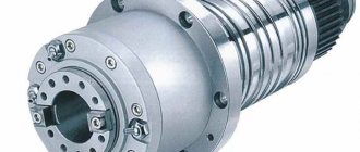
The spindle is a steel shaft, in front of which there is a mount for the working tool. In the classic style, the spindle is mounted on high-precision rolling bearings. To ensure the required accuracy of operation during operation, a special ring is installed on the spindle support. The ring is adjusted using an adjusting nut, which, when tightened, moves the nut along the spindle, which ensures the elimination of gaps formed during operation.
The design of the spindle depends on many factors, usually on the application, the type and design of the machine, the size and speed of operation. Previously, the basis of this unit was bearings, the deviation on which reached 1 micron. Today, the requirements for spindles have increased, so modern samples are made using magnetic or air supports. This solution makes it possible to achieve a minimum deviation not exceeding 0.2 microns.
For higher precision, at which the processing error is below 0.03 µm, a special drive method is used. The spindle is driven and accelerated by the flywheel, but the work is performed after the flywheel is turned off and the spindle operates due to inertia.
The design of the unit must meet the following requirements:
- Accuracy. It is selected based on the machine model, the material being processed and technological requirements.
- Speed. Different types of spindles rotate at different speeds, the faster the speed of processing the workpiece, the higher the quality of the work performed.
- Rigidity. It is determined by the ratio of the spindle deflection and the level of radial runout. The lower this indicator, the higher the quality of work.
- Durability. The service life of the unit primarily depends on the quality of the bearing used.
- Vibration resistance. The spindle must be vibration tolerant to the external vibration of the machine, which ensures high precision of the tool.
- Permissible heating. It is determined by the maximum heating temperature of the unit at which the operating characteristics of the spindle do not change.
- Load bearing capacity. Characterizes the recommended weight and dimensions of the working tool.
Typically the spindle is not considered as a separate structure. Most often, the entire complex of a screw-cutting lathe is considered, including an electric motor, drive, headstock and spindle. The electric motor can be changed, even power plants operating on direct current can be used. The main thing is that all components correspond to the electrical circuit of the machine.
Download GOST 12593-93
Technical characteristics of the lathe 16K20
| Parameter name | 16K20 | 16K20P |
| Basic machine parameters | ||
| Accuracy class according to GOST 8-82 | N | P |
| The largest diameter of the workpiece installed above the bed, mm | 400 | 400 |
| Height of the center axis above the flat guides of the frame, mm | 215 | 215 |
| The largest diameter of the workpiece processed above the support, mm | 220 | 220 |
| Maximum length of the workpiece installed in the centers (RMC), mm | 710, 1000, 1400, 2000 | 710, 1000 |
| The greatest distance from the axis of the centers to the edge of the tool holder, mm | 225 | 225 |
| The largest diameter of the drill when drilling steel parts, mm | 25 | 25 |
| Maximum mass of workpiece processed in centers, kg | 460..1300 | 460..1300 |
| Maximum mass of workpiece processed in the chuck, kg | 200 | 200 |
| Spindle | ||
| Spindle hole diameter, mm | 52 | 52 |
| The largest diameter of the rod passing through the hole in the spindle, mm | 50 | 50 |
| Spindle rotation speed in forward direction, rpm | 12,5..1600 | 12,5..1600 |
| Spindle rotation speed in reverse direction, rpm | 19..1900 | 19..1900 |
| Number of forward spindle speeds | 22 | 22 |
| Number of spindle reverse speeds | 11 | 11 |
| Spindle end according to GOST 12593-72 | 6K | 6K |
| Tapered spindle bore according to GOST 2847-67 | Morse 6 | Morse 6 |
| Spindle flange diameter, mm | 170 | 170 |
| Maximum torque on the spindle, Nm | 1000 | 1000 |
| Caliper. Submissions | ||
| Maximum length of longitudinal movement, mm | 645, 935, 1335, 1935 | 645, 935 |
| Maximum length of transverse movement, mm | 300 | 300 |
| Speed of fast longitudinal movements, mm/min | 3800 | 3800 |
| Speed of fast transverse movements, mm/min | 1900 | 1900 |
| Maximum permissible speed of movement when working on stops, mm/min | 250 | 250 |
| Minimum permissible speed of movement of the carriage (support), mm/min | 10 | 10 |
| Price for dividing the longitudinal movement dial, mm | 1 | 1 |
| Transverse movement dial division price, mm | 0,05 | 0,05 |
| Longitudinal feed range, mm/rev | 0,05..2,8 | 0,05..2,8 |
| Transverse feed range, mm/rev | 0,025..1,4 | 0,025..1,4 |
| Number of longitudinal feeds | 42 | 42 |
| Number of cross feeds | 42 | 42 |
| Number of threads to be cut - metric | ||
| Number of threads to be cut - modular | ||
| Number of threads cut - inch | ||
| Number of threads to be cut - pitch | ||
| Limits of metric thread pitches, mm | 0,5..112 | 0,5..112 |
| Limits of pitches of inch threads, threads/inch | 56..0,5 | 56..0,5 |
| Limits of modular thread pitches, module | 0,5..112 | 0,5..112 |
| Limits of pitch thread pitches, diametric pitch | 56..0,5 | 56..0,5 |
| The greatest force allowed by the feed mechanism on the cutter is longitudinal, N | 5884 | 5884 |
| The greatest force allowed by the feed mechanism on the cutter is transverse, N | 3530 | 3530 |
| Cutting slide | ||
| Maximum movement of the cutting slide, mm | 150 | 150 |
| Movement of the cutting slide by one division of the dial, mm | 0,05 | 0,05 |
| Maximum angle of rotation of the cutting slide, degrees | ±90° | ±90° |
| Scale division of the tool slide rotation scale, deg | 1° | 1° |
| The largest cross-section of the cutter holder, mm | 25 x 25 | 25 x 25 |
| Height from the supporting surface of the cutter to the axis of the centers (cutter height), mm | 25 | 25 |
| Number of cutters in the cutting head | 4 | 4 |
| Tailstock | ||
| Tailstock quill diameter, mm | ||
| Cone of the hole in the tailstock quill according to GOST 2847-67 | Morse 5 | Morse 5 |
| Maximum movement of the quill, mm | 150 | 150 |
| Movement of the quill by one division of the dial, mm | 0,1 | 0,1 |
| The amount of lateral displacement of the headstock body, mm | ±15 | ±15 |
| Electrical equipment | ||
| Main drive electric motor, kW | 11 | 11 |
| Electric motor for fast movement drive, kW | 0,12 | 0,12 |
| Coolant pump electric motor, kW | 0,125 | 0,125 |
| Dimensions and weight of the machine | ||
| Machine dimensions (length width height) RMC=1000, mm | 2795 x 1190 x 1500 | 2795 x 1190 x 1500 |
| Machine weight, kg | 3010 | 3010 |
Criterias of choice
Choosing a milling machine begins with an analysis of the material it will have to work with: metal or wood.
Then technological operations and the scope of work are analyzed. When choosing a spindle, pay attention to its main characteristics:
- rotation frequency;
- power;
- design;
- speed adjustment;
- method of attaching the tool;
- work performed;
- type of cooling.
It is worth paying attention to the current connected to the equipment
Power
The choice of spindle power is determined by the hardness of the material being processed. For wood and boards made from its waste - chipboard, MDF, a power of up to 3 kW is sufficient. The equipment can process plastic, plywood, and do engraving.
Non-ferrous metals and their alloys are relatively soft, but have a high viscosity coefficient. A clean cut is obtained only with a power of up to 6 kW and a rotation speed of 18,000 rpm. Machining steel and cast iron requires a spindle with a power of more than 6 kW and a rotation speed of up to 22,000 rpm. Depending on the hardness and viscosity of the material, the modes are selected by a combination of rotation speed and feed rate.
Milling method
Milling is done in a counter and reverse manner. The rotation of the tool is directed against the movement of the part or coincides with it.
There are processing modes:
- power;
- express
In the power mode, processing occurs with a large feed, at low speeds, due to the power of the spindle. The cutting edge captures a thick layer of material every time. The high-speed mode assumes the ability of the tool to rotate at high speed. The table service is small. The mode is suitable for non-ferrous metals and wood and guarantees high cleanliness of the treated surface.
Important! Cast iron can be processed well at low speeds and low feed rates. He doesn't like high speeds.
Cooling
Milling spindles have 2 types of cooling:
- air;
- water
For cooling by air flows, special slots are made in the unit body. When the shaft rotates, turbulence occurs and cold air is drawn in from outside. The water cooling system is complex in design. It must be sealed. Air-cooled spindles installed on home equipment last longer.
On industrial equipment, bearings reduce friction and heating of the spindle. Enough air flow. The gearbox is lubricated and cooled with oil. The engine has its own cooling system - an impeller on a shaft.
Workpiece material
Cutting modes and sharpening angle of the cutting edge are selected according to the characteristics of the workpiece material.
Tree
A clean cut is obtained when processing wood with a rapidly rotating tool. Feed and cutting depth are small. The spindle is suitable for high-speed, with a power of up to 1.5 kW.
Important! When processing wood in a power mode, chips and cracks between the fibers form on the part, and the surface becomes rough.
Metal
Cutting metal requires a lot of power and high strength of the unit. During machining of a part, in addition to the torque, resistance acts on the spindle. Its force is directed perpendicular to the axis of rotation.
Metal spindles have a durable, massive body, mostly cast iron. The shaft is equipped with thrust and radial bearings. The rotation speed of the tool should be adjusted between 20–18,000 rpm.