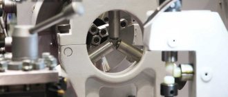
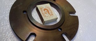
Extension method without welding with modification
In this review, the author shows how to lengthen the shaft of an electric motor if it is not possible to do this work on a lathe. The information will be useful to all DIYers.
An electric motor from a washing machine is used as a “test subject” - one of the most affordable motors today.
First of all, the master resolders the wires so that the motor shaft rotates in the opposite direction. Then we turn on the motor, and using a drill with a diameter of 5 mm, we drill a hole in the center of the shaft (depth - at least 30 mm).
We gradually drill out the hole, bringing it to 8.5 mm in diameter. Next you will need to cut a thread for the M10 bolt.
We tighten the bolt until it stops, and then unscrew it one turn back. To do this, it is necessary to fix the second end of the shaft.
Main stages of work
At the next stage, mark and drill a through hole in the M10 bolt (or stud). At the end of the shaft it is necessary to make two grooves opposite each other with a depth of approximately 1.5-2 mm.
Then we shorten the bolt to the required length, and we get a stud, which is a continuation of the engine shaft.
We screw it into the shaft (you can just do it, you can use epoxy glue). You can even use thread locker.
Details on how to lengthen the shaft of an electric motor with your own hands can be seen in the video on our website.
Andrey Vasiliev
Ask a Question
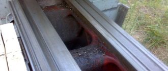
How to reduce the diameter of a bar without a machine?
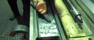
The topic is outdated, BUT! If you don’t have a machine, and you desperately need to reduce the diameter, I used the following method: a groove is milled in a flat piece of wood into which the rod is placed (the groove is needed as a guide, but you can do without it (the main thing is that the piece of wood is as smooth and flat as possible). The rod is fixed to area not to be processed. To the left and right of the part of the bar to be processed, plates are placed of such a height that their height is lower than the height of the bar by the amount that needs to be removed. To control the removal, the bar is painted with a permanent marker. Next - a face file. After After removing metal to the level of the plates that limit the height, the rod is loosened in the fastening and rotated at the angle required for processing. And so - many, many times. The smaller the height difference between the planes of the limiting plates and the processed rod, the closer the profile is to a perfectly round one. For To limit the processing length, you can wrap a ring of electrical tape around the rod, or put on a sleeve of a suitable diameter.
After making a “full circle,” the rod is painted again with a marker and the procedure is repeated. It is advisable to remove no more than 0.02 at a time (that is, the average amount of facial file removal per pass). The more approaches, the more accurate the result will be. That is, the thinner the file cut and the more revolutions.
Finishing - the sandpaper, folded with a “sling”, the working surface inward, grinds the processed end of the rod clamped in a vice.
The method is extremely labor-intensive and is applicable to extremely small processing areas, however, depending on the number of passes, it gives an extremely accurate result, comparable to processing on a high-precision lathe, or better. In my case, I managed to get into flight when processing a stud on which an SKF angular contact bearing was attached for auto repair of a BMW engine (the stud was made from a rod with a diameter of 18 mm, it was necessary to grind down the part inserted into the engine block to 16.5 mm, bearing seat - up to 12 mm).
The same result can be achieved faster by using a rigidly fixed grinder with a grinding wheel, under which the rod being processed is brought clamped in the block.
After the rod has completely rotated in the block, the block is set higher by placing measuring probes under it. This will already be a kind of “desktop version” of a surface grinding machine - the block can be mounted on furniture ball guides, for example... The accuracy will be lower, but still extremely acceptable. Modified October 12, 2021 by ichnevmon1
Boring the jaws of a lathe chuck: how to grind it correctly, video
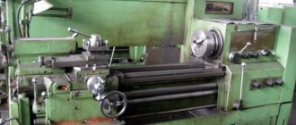
When working on a lathe, craftsmen are faced with wear and tear on the main components of the equipment. Intensive work at high speeds, the level of wear on the mat is very high.
This leads to beating of the workpiece. In this case, it is not necessary to replace in detail a new one. Sometimes, to correct the situation, it is enough to simply bore the jaws of the lathe chuck.
Why do you need a boring
The purpose of boring is to align the axis of the working surfaces of the chuck jaws with the axis of rotation of the spindle. The cams need to be bored when they are in the clamped position. If the process is carried out in a free state, the beating will not be eliminated.
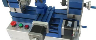
How to turn a shaft without a lathe?
» Other »
Question for experts: It is necessary to machine a shaft with a length of 744 mm and a diameter of 45 mm into a size with a diameter of 42 mm without a rest and a second frame. Tell me the cutting modes and conditions, then I thought I’d get “Amur waves.” And what is needed is cleanliness and disrepair.
Best regards, Vovan
Best answers
The shafts must be centered on both sides, no matter what modes you set, this length will “go away”. This is not a question of modes, rather a question of a 740+mm lever that will respond to any pressure from the cutter. The maximum I can offer you is to move the workpiece if the machine allows it (through headstock with a diameter of 42/45).
That is, fasten in the middle, and then re-fasten with the other side. At least it won’t be 744, but 370+. Or even sharpen in pieces in the chuck area, move inward, sharpen the next piece, shift again. . If it doesn’t allow it, make a homemade steady rest, or simply buy the cheapest one - there will actually be less fuss and damage to the workpieces.
No, of course, you can shoot in hundreds, feed in hundreds and make 3000 cycles. To essentially “scratch” the shaft. The CNC will do this, it will make noise for a long time, but it will do it, but if you dig in manually, you won’t get clean anyway.
PS For advice on cutting conditions, come with information about the material and available cutters.
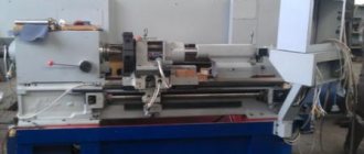
Machining shafts on lathes
Turning of metal parts is the process of removing allowance from the surface of the workpiece due to chip formation. In this case, mechanical deformations occur, accompanied by friction and, as a consequence, heating of the product and working tool. One type of turning is shaft turning.
A shaft is a round cylindrical part whose length is much greater than its diameter. The shape of the shafts is divided into smooth and stepped. When processing smooth shafts, the specified dimensions and roughness parameters must be maintained. Additional requirements are imposed on stepped shafts: the alignment of individual cylindrical sections and compliance with the perpendicularity of the shoulders to the axis of rotation.
General information
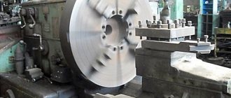
For the manufacture of shafts, blanks with a large allowance are used, which are clamped in a chuck and pressed by the rear center. When roughing, it is necessary to remove the allowance as much as possible, using the greatest depth of cut, determined by the power of the machine. The remaining allowances for final processing are calculated based on the configuration and dimensions of the part, and subsequent processing methods.
When the ratio of the shaft diameter to its length is more than 1:15, movable and fixed rests are used. These supporting devices absorb the reaction of the cutting forces, preventing deformation of the workpiece. This increases the rigidity of the cutting system and reduces the likelihood of unwanted vibrations.
Finishing of shafts is carried out in centers, while the end of the shaft is fixed in a driving chuck or a clamp is used. When processing single products, one side of the shaft is passed in one installation using all the necessary tools. Large batches of products are manufactured on various machines using a minimal set of tools.
Finishing is carried out using high-precision equipment. In this case, processing begins with the largest diameter, successively moving to the next smaller size.
Machining smooth shafts
Making a smooth shaft involves turning the outer cylindrical surface. The work is performed with a through cutter using longitudinal feed. In this case, the workpiece is installed in the centers.
Center holes are made on various machines: lathes, drills, turrets. On special double-sided centering machines, simultaneous turning of opposite centers is carried out. In any case, twist drills, countersinks or a combined centering tool are used for this operation.
The quality of manufacturing of the entire part depends on the accuracy of the centering holes, called mounting bases.
When manufacturing a smooth shaft, the following operations are performed:
- Cutting a workpiece from a common rod.
- End surface processing followed by centering
- Making the opposite end plane and centering it.
- Roughing one half of the workpiece located in the centers.
- Roughing of the second part of the workpiece.
- Consecutive finishing of the first and second parts of the workpiece.
It must be said that the most economical way to make a smooth shaft is to use calibrated steel. In this case, there is no need to process the outer cylindrical surface. But in most cases, long products are used. Therefore, when choosing a workpiece, you need to take the outer size of the rod with the diameter closest to the maximum cross-section of the future shaft.
Manufacturing of stepped shafts
Stepped shafts are manufactured according to two schemes:
- Dividing the allowance into parts.
- Dividing the length of the workpiece into several segments.
The first scheme involves processing a workpiece with a small depth of cut. In this case, the total distance traveled by the cutter is greater. In the second case, the allowance is removed in one pass with a large cutting depth. With this approach, a more powerful electric drive of the machine is required.
Before processing the cylindrical surface, the ends are trimmed. The operation is carried out with a scoring cutter with feed in two directions. Cutting from the center to the surface of the shaft has a less rough surface quality.