How the bed and headstock of the machine are arranged
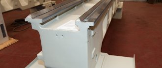
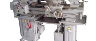
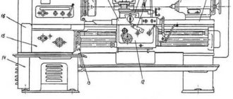
The frame is a supporting element on which all other structural elements of the unit are installed and fixed. Structurally, the frame consists of two walls connected to each other by transverse elements that give it the required level of rigidity. Individual parts of the machine must move along the bed; for this purpose, it is equipped with special guides, three of which have a prismatic section, and one has a flat section. The tailstock of the machine is located on the right side of the bed, along which it moves thanks to internal guides.
Read also: Repair of chain sharpening machines
The cast lathe bed is reinforced with stiffening ribs and has ground and hardened guides
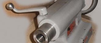
The headstock simultaneously performs two functions: it gives the workpiece rotation and supports it during processing. On the front part of this part of the lathe (it is also called the “spindle head”) there are gearbox control handles. With the help of such handles, the machine spindle is given the required rotation speed.
In order to simplify the control of the gearbox, next to the shift knob there is a plate with a diagram that indicates how to position the handle so that the spindle rotates at the required frequency.
Speed selection lever for BF20 Yario machine
In addition to the gearbox, the headstock of the machine also contains a spindle rotation unit, in which rolling or sliding bearings can be used. The device chuck (cam or drive type) is fixed at the end of the spindle using a threaded connection. It is this unit of the lathe that is responsible for transmitting rotation to the workpiece during its processing.
The frame guides along which the machine carriage moves (the lower part of the support) have a prismatic cross-section. They are subject to high demands on parallelism and straightness. If these requirements are neglected, it will be impossible to ensure high quality processing.
bed
The main fixed part of the machine is the bed, consisting of 2 vertical ribs. Between them there are several transverse crossbars that ensure the rigidity and stability of the stator.
The bed is located on legs, their number depends on the length of the bed. The design of the cabinet legs is such that they can store the tools necessary for the operation of the machine.
The upper transverse rails of the frame serve as guides for the movement of the caliper and tailstock along them. Comparing machine diagrams, it is easy to notice that in some designs two types of guides are used:
- prismatic for moving the caliper;
- flat guide for tailstock travel. In very rare cases it is replaced by a prismatic type.
Purpose of the tailstock of turning equipment
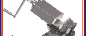
The tailstock of a lathe, the design of which can include several design options, is necessary not only for fixing parts of considerable length, but also for fastening various tools: drills, taps, reamers, etc. An additional center of the machine, which is installed on the tailstock, can be rotating or stationary.
Tailstock structure: 1, 7 – handles; 2 – handwheel; 3 – eccentric; 4, 6, 9 – screws; 5 – traction; 8 – quill; A – counterbore
A scheme with a rotating rear center is used if the equipment is used for high-speed processing of parts, as well as when removing chips that have a large cross-section. When implementing this scheme, the tailstock is made with the following design: two bearings are installed in the quill hole - a front thrust bearing (with tapered rollers) and a rear radial one - as well as a bushing, the inner part of which is bored to a cone.
Axial loads arising during processing of a part are absorbed by a thrust ball bearing. Installation and fixation of the rear center of the equipment is ensured by the tapered hole of the bushing. If it is necessary to install a drill or other axial tool in such a center, the sleeve can be rigidly fixed with a stopper, which will prevent it from rotating with the tool.
Rotating center KM-2 of a table lathe Turner-250
The tailstock, the center of which does not rotate, is fixed to a plate that moves along the guides of the machine. The quill installed in such a headstock moves along the hole in it using a special nut. In the front part of the quill itself, into which the center of the machine or the shank of the axial tool is installed, a conical hole is made. The movement of the nut and, accordingly, the quill is ensured by the rotation of a special flywheel connected to the screw. What is important is that the quill can also move in the transverse direction; without such movement it is impossible to process parts with a flat cone.
Feed mechanism
The feed mechanism tells the caliper the required direction of movement. The direction is set with a bit. The bit itself is located in the headstock housing. It is controlled via external handles. In addition to the direction, you can also change the amplitude of movement of the caliper using interchangeable gears of different numbers of teeth or a feed box.
In the scheme of machines with automatic feed, there is a lead screw and a roller. When carrying out high-precision work, a lead screw is used. In other cases, a roller is used, which allows you to keep the screw in ideal condition longer for performing complex elements.
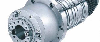
Spindle as an element of a lathe
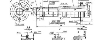
The most important structural component of a lathe is its spindle, which is a hollow metal shaft with a conical inner hole. What is noteworthy is that several structural elements of the machine are responsible for the correct functioning of this unit. It is in the inner conical hole of the spindle that various tools, mandrels and other devices are fixed.
Spindle drawing of screw-cutting lathe 16K20
In order to be able to install a faceplate or a lathe chuck on the spindle, its design includes a thread, and to center the latter there is also a collar on the neck. In addition, to prevent spontaneous unscrewing of the chuck when the spindle is quickly stopped, some models of lathes are equipped with a special groove.
The results of machining parts made of metal and other materials on the machine largely depend on the quality of manufacturing and assembly of all elements of the spindle assembly. In the elements of this unit, in which both the workpiece and the tool can be fixed, there should not be even the slightest play that causes vibration during the rotational movement. This must be carefully monitored both during the operation of the unit and when purchasing it.
In spindle units, which can be immediately determined from their drawing, sliding or rolling bearings can be installed - with roller or ball elements. Of course, rolling bearings provide greater rigidity and accuracy; they are installed on devices that process workpieces at high speeds and with significant loads.
Toolholder control
The tool holder is a fairly precise mechanism that ensures rigidity of the tool attachment in specified positions. The correct position of the tool holder handle when clamped should correspond to the clockwise position at 3-4 o'clock. This position is ensured by the position of the spacer washer under the nut of the tool holder handle. The lever is clamped with an average elbow force. And pressing the handle cannot be done using your own weight to avoid weight loss. Squeezing the handle is done with one or more short pushes with the heel of the palm in a counterclockwise direction. Before rotating the tool holder, make sure there are no obstructions to the tool holder or the tool attached to it. Obstacles from the rotating elements of the machine pose a great danger.
Caliper structure
A lathe support is a unit that ensures the fixation of the cutting tool, as well as its movement in the inclined, longitudinal and transverse directions. It is on the support that the tool holder is located, moving with it due to a manual or mechanical drive.
Read also: Converting a computer power supply to 12 volts
Support with carriage for machine Optimum D140x250
The movement of this unit is ensured by its structure, which is characteristic of all lathes.
- The longitudinal movement, for which the lead screw is responsible, is performed by the caliper carriage, while it moves along the longitudinal guides of the frame.
- Transverse movement is performed by the upper - rotating - part of the support, on which the tool holder is installed (such movement, due to which the depth of processing can be adjusted, is carried out along the transverse guides of the support itself, which are shaped like a dovetail).
Quick-change tool holder MULTIFIX cartridge type
The tool holder, also called the cutting head, is installed on the top of the support. The latter can be fixed at different angles using special nuts. Depending on the need, single or multiple tool holders can be installed on lathes. The body of a typical cutting head has a cylindrical shape, and the tool is inserted into a special side slot in it and secured with bolts. There is a protrusion on the bottom of the cutting head that fits into a corresponding slot on the support. This is the most typical tool holder mounting scheme, used primarily on machines designed to perform simple turning work.
How to repair a caliper carriage
Technical characteristics of the lathe DIP 500, diagrams
A major overhaul of the caliper carriage involves restoring its lower guides connected to the frame guides. In addition, when restoring this unit, it is necessary to ensure that the plane of its movement is perpendicular to the planes on which the apron of the lathe and its feed box are fixed. To determine the degree of deviation of these planes from the norm, a level and probes of various thicknesses are used.
As a result of a major overhaul, the lathe carriage must be aligned parallel to the transverse travel of the support with an accuracy of 0.02 mm over a length of 300 mm. This parameter is checked using a special indicator, which is fixed in the tool holder of the lathe.
The support (see Fig. 1a) is designed to move the cutting tool fixed in the tool holder during processing. It consists of a lower slide (longitudinal slide) 1, which moves along the frame guides using a handle 15 and ensures the movement of the cutter along the workpiece. On the lower slide, transverse slides (transverse slide) 3 move along guides 12, which ensure the movement of the cutter perpendicular to the axis of rotation of the workpiece (part). On the transverse slide 3 there is a rotary plate 4, which is secured with a nut 10. The upper slide 11 moves along the guides 5 of the rotary plate 4 (using the handle 13), which together with the plate 4 can be rotated in a horizontal plane relative to the transverse slide and ensure the movement of the cutter at an angle to the axis of rotation of the workpiece (part). The tool holder (cutting head) 6 with bolts 8 is attached to the upper slide using a handle 9, which moves along the screw 7. The support movement is driven from the lead screw 2, from the lead shaft located under the lead screw, or manually. Automatic feeds are turned on using handle 14.
Rice. 1a. Lathe support 16K20
Technical jaw chuck
On lathes, two-, three- and four-jaw chucks with manual and mechanized clamping drives are used. Various shaped castings and forgings are secured in two-jaw self-centering chucks; The jaws of such chucks are usually designed to secure only one part. Three-jaw self-centering chucks hold round and hexagonal workpieces or large diameter round rods. In four-jaw self-centering chucks, square-section rods are fixed, and in chucks with individual adjustment of the jaws, parts of rectangular or asymmetrical shape are fixed. A three-jaw self-centering chuck with a manual clamp is the most common device for fastening parts on lathes. Possessing a powerful but sensitive mechanism, the chuck allows you to reliably fasten parts with high accuracy of their centering, both for high-speed processing and for more delicate work. The lathe chuck can be mounted on the spindle of a machine tool or device. The most widely used is a three-jaw self-centering chuck (figure below). Cams 1, 2 and 3 of the cartridge move simultaneously using disk 4. On one side of this disk there are grooves (shaped like an Archimedean spiral) in which the lower projections of the cams are located, and on the other there is a cut bevel gear mated to three bevel gears 5. When you turn one of the wheels 5 with a key, disk 4 (thanks to gearing) also turns and, by means of a spiral, simultaneously and evenly moves all three cams along the grooves of the cartridge body 6. Depending on the direction of rotation of the disk, the cams move closer to the center of the chuck or move away from it, clamping or releasing the part. The cams are usually made in three stages and are hardened to increase wear resistance. There are cams for securing workpieces on the internal and external surfaces; when fastening on the inner surface, the workpiece must have a hole in which the cams can be placed.
Electrical part of a lathe
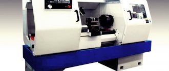
All modern lathes and screw-cutting lathes for metal, which are characterized by a fairly high complexity of their design, are driven by a drive, which uses electric motors of various powers. Electric motors installed on such units can be asynchronous or powered by direct current. Depending on the model, the engine can produce one or more rotation speeds.
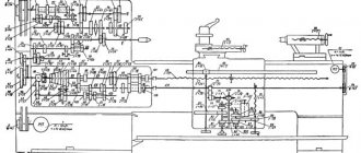
Electrical diagram of a 1K62 lathe (click to enlarge)
Most models of modern metal lathes are equipped with squirrel-cage motors. To transmit torque from the engine to the elements of the machine's gearbox, a belt drive or direct connection to its shaft can be used.
On the modern market there are also models of lathes in which the spindle rotation speed is controlled in a stepless manner using electric motors with independent excitation. The shaft rotation speed of such a motor can be adjusted in the range of 10 to 1. However, due to their large dimensions and not very economical electricity consumption, such electric motors are used extremely rarely.
Two-speed motor with flat belt pulley
As mentioned above, electric motors operating on direct current can also be used to drive lathes. It is these electric motors, characterized by large dimensions, that provide a stepless change in the speed of rotation of their output shaft.
The electric motor is the main part of the electrical system of any lathe, but it also includes a lot of additional elements. All of them, functioning in a complex, provide ease of control of the machine, as well as the efficiency and quality of the technological operations that are performed on it.
Screw-cutting lathes are multifunctional metalworking equipment capable of performing a whole range of technological operations, including turning, boring, end processing, countersinking, reaming and trimming.
This article discusses the design, functional purpose, operating principle and capabilities of lathe group machines. We will study the market for the most common models and get acquainted with their technical characteristics.
Table of contents
Lathes are widely used in modern industry, for example, models such as the TV-320 screw-cutting lathe, as they allow you to perform many operations on processing cylindrical parts. Their design largely depends on the models, but there are always similar elements, since the main parts are the same for all, even if they have their own characteristics. The lathe support is one of the most important parts of the machine as it is responsible for mounting the cutter. It was its appearance that made a revolutionary step in machine tool building. This element is intended to move the cutting tool, which is located in the tool holder, when processing the workpiece in several planes.
photo: lathe support
Movement is carried out in three main directions relative to the machine axis:
Movements in given directions are carried out both manually and mechanically.
Lathe support device
photo: lathe support device
The lathe support has the following components:
- Lower slide (or longitudinal support);
- Lead screw;
- Cross slide (or cross slide);
- Rotary plate;
- Guides;
- Cutting head (tool holder);
- Screw;
- Fastening bolts;
- Fastening handle;
- Locking nut;
- Upper slide;
- Guides;
- Handle for moving the rotary plate;
- Handle for turning on automatic feeds;
- A handle that provides control of movement along the bed;
The principle of operation of the caliper
The support of a lathe has a very complex control system, since it includes many parts. Each of the elements performs its own function, ensuring the overall performance of the mechanism. For example, the support of a screw-cutting lathe has a lower slide No. 1, which can move along the bed guides during operation to get to the workpiece. Movement is regulated by handle No. 15. Thanks to movement on the slide, longitudinal movement along the workpiece is ensured.
The transverse support of the T3 lathe also moves on the same slide, which carries out transverse movements along its guides No. 12. Thus, all this covers the movement area, which lies perpendicular to the axis of rotation of the workpiece. By the way, if you are interested in the architectural design of buildings and structures, go to the website https://aec-project.ru/services/proektirovanie/.
On the cross slide there is a rotating plate No. 4, which is attached to it with a special nut No. 10. Guides No. 5 are installed on the rotating plate, along which the upper slide No. 11 runs. The upper slide is controlled using the rotary handle No. 13. The upper slide rotates in a horizontal plane simultaneously with the plate. It is this unit that ensures the movement of the cutter, which is carried out at an angle to the axis of rotation of the part.
The cutting head, or as it is also called - the tool holder, No. 6 is fixed on the upper slide using special bolts No. 8 and handle No. 9. The movement from the caliper drive is transmitted through lead screw No. 2 to the drive shaft, which is located under this same screw. This can be done either automatically or manually, depending on the model.
Basic caliper movements
- Transverse movement is carried out perpendicular to the axis of rotation of the workpiece and is used in cases where it is necessary to machine something deep into the surface of the workpiece;
- Longitudinal movement is carried out along the workpiece and is used in cases where it is necessary to remove the top layer or grind a thread on the workpiece;
- Inclined movement is carried out along an inclined plane and significantly expands the processing capabilities of this equipment.
Adjusting the lathe slide
The support of a lathe wears out during its operation and requires adjustment of individual parts to continue working correctly:
- Adjusting the gaps. As the slide guides wear, a gap appears that should not exist. Its appearance can cause interference in the uniform movement of the sled, jamming in one place and lack of swaying when lateral forces are applied. To correct this situation, it is necessary to move the guides to the proper position and eliminate the excess gap. This is done using wedges, and the carriage is pressed against the guides.
- Backlash adjustment. If play appears in the screw drive, it can be easily eliminated by adjusting the fastening nut located on the device.
- Adjusting the seals. During prolonged work at the ends of the carriage protrusion, the seals become clogged and worn out, which can be easily seen by the appearance of dirty streaks that remain when the frame moves. In this case, to adjust the device, you should wash the felt padding and then soak it in oil. If it is completely worn out, it is easier to replace it with a new one.
Lathe support repair
The support of the 1K62 lathe wears out over time and may break. Most wear is noticeable along the guides of the device. Over time, the surface of the guide slide can form small depressions that interfere with normal movement. To prevent this, it is necessary to ensure timely care and lubrication, but if this does happen, then the surface of the guides must be leveled or replaced if repair cannot be achieved.