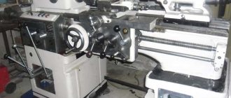
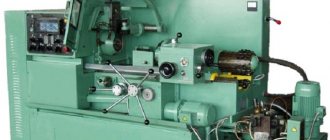
Lathe equipment is popular both in large enterprises and in home workshops. With their help, you can perform various technological processes: work with wood, plastic, metal. However, beginners often have problems processing long workpieces. They sag and bend. To hold parts during processing, it is recommended to use a lathe rest.
Steady rest for lathe
Do-it-yourself steady rest for a lathe
In the mechanical engineering industry, a steady rest is a device that is an additional support for a metal-cutting machine for rotating workpieces. The steady rest prevents bending of the part, which can occur due to the force during cutting, which can also be caused by its own weight. This device serves to provide greater vibration resistance to the part. It is usually used in the processing of long parts. These include long non-rigid shafts; we can also talk about parts with protruding parts.
Usage
In normal practice, the steady rest is used on the following machines:
- cylindrical grinding;
- slot milling;
- thread milling;
The device in question, depending on the processing method and technological conditions, may be stationary in nature if, as is usually the case, it is attached to the frame or has mobility. In the latter case, the steady will move in the same way as the carriage, support and other parts of the machine.
All these devices are divided into two types, depending on the type of support. If there is a support that uses rolling during movement, then we are talking about roller rests, and if sliding, then cam rests. Shoes are a type of special steady rest, the field of use of which is grinding, to which rings of bearings or rollers are subjected in a manner called centerless.
The most common devices in simple machine tools are devices that have manual, independent movement of the cams. If we are talking about machines with numerical control, then devices equipped with a hydraulic drive are most often used here. In this case, the operating principle of the steady rest is self-centering.
Undoubted advantages
The main positive property of the devices in question is the significant degree of impact on the part during its processing. The accuracy of the operation increases, while form errors are transferred to the workpiece being processed. These parameters are determined in coefficients, which are different for each steady rest design. They are minimal for corrective devices.
Source: specural.com
Weaving Looms › DIY Handloom
We offer frames for hand weaving produced by Klass&Gessmann (Germany). The range includes products for both adults and little needlewomen. Name.
DIY machine › Homemade Lathe
A homemade foot-operated lathe is an excellent alternative to modern lathes and can be used for the manufacture of simple products even where.
Movable steady rest and its structure
This device is located on the longitudinal support of the machine. Thanks to this arrangement, the mobile steady rest performs movements with the same trajectory as the machine cutter. Thus, the pressure on the part from the turning tool is reduced. The movable type of device also has its own classification:
- According to the clamp system. There are roller and cam fixation systems. Fastening with rollers ensures convenient sliding of the workpiece during work, while cams provide better control over the position of the part.
- According to the specifics of processing. Different types of tools can be used for grinding, turning or creating bearings.
- By type of clamp settings. In these devices, the cams or rollers can be adjusted manually or using a hydraulic drive.
- By the number of fasteners. Most devices are manufactured with three cams, but there are models with more clamps.
The mobile steady rest is attached to the support carriage and is used in cases where there is a need to perform clean turning or make threads on long workpieces. Like a fixed steady rest, thanks to adjustable cams, it has the ability to fix parts of completely different diameters.
The maximum diameter of the workpiece being processed depends on the device model and ranges from 20 to 250 mm. Key elements of the movable steady rest design:
- Hinged lid.
- Blank for processing.
- Pads.
- Screws for installation.
- Frame.
Design and principle of operation
The steady rest is not a universal device, so its capabilities are determined by the design and technical characteristics of the lathe. However, its design must contain the following details:
- The housing through which the lathe's steady rest is connected to its carriage or support.
- Top clamp that prevents the cutter from lifting onto the holder.
- A lower stop that compensates for the deflection of the workpiece under the influence of its own weight.
- Support cams (or balls) that directly contact the surface of the workpiece, positioning it relative to the center.
A set of replaceable stops is usually supplied with the steady rest, the number and dimensions of which depend on the standard size of the machine. For example, the 1M63 fixed steady rest is distinguished by its maximum load capacity, and the steady rest for the 16K20 machine is distinguished by the ability to replace the supporting elements from bushings to ball ones. In this case, the sliding friction of the workpiece turns into rolling friction, which accordingly reduces friction and wear of the guide parts.
Starting with model 1K62, steady rests are produced not only in fixed, but also in movable versions. The latter, although more complicated, allow the stop to be moved along the axis of the workpiece as the cutter moves. The latter, by the way, moves the lathe rest along the carriage using the movement of the tool holder. The turner's hands can thus perform other, more complex adjustment transitions at this time.
What does it consist of?
The fixed steady rest is rigidly fixed to the machine bed. The correct orientation relative to the chuck is organized by installing a frame on a flat and prismatic guide along which the tailstock moves.
Composition of the device:
- base;
- pressing bar;
- fixing screw;
- hinged lid;
- hinge;
- hinged bolt;
- screw;
- supports - 3 pieces;
- screw mechanisms;
- heads.
The operating principle is as follows: having installed the steady on the frame, it must be secured at the required distance from the chuck. To do this, a pressing bar is used, which is tightened with a screw and rests against the lower surface of the guides. After which the lid is opened and the workpiece is secured.
After fixing the workpiece, the lid is closed . A reliable connection is ensured by a nut with a hinged bolt. The turner, rotating the heads of the screw mechanisms, moves the supports towards the shaft. The final fastening is carried out with the part rotating.
It is worth remembering that when processing round-rolled , after forging or stamping, before starting work, the place where the supports come into contact with the workpiece must first be ground. The outer surface of the workpiece is uneven and the steady will not perform its function. But if finishing processing is carried out, then there is no need for grooving.
The movement of the supporting surfaces is carried out not only manually with a screw pair , but also with the help of drive devices. In most cases, a hydraulic drive and hydraulic cylinders are used for this. The clamping force is regulated by pressure in the hydraulic system.
The movable steady rest is so named because it moves with the carriage on which it is attached. For this purpose, manufacturers have provided two threaded holes. It moves along with the cutter in the longitudinal direction, so processing stepped shafts is difficult or is limited in processing length.
The lathe and steady rest are installed separately. The use of movable devices is typical for thread cutting and finishing turning over long distances.
The structure includes the same elements as the fixed one, with the exception of the pressing bar and the fixing bolt.
DIY lunette
Many home craftsmen have lathes for processing metal and wood. And, faced with the problem of turning long parts, they ask themselves: how to make a homemade steady rest?
First, you need to find on the Internet and download a drawing of the original design designed for the type of equipment used. To make a steady rest for a lathe with your own hands, you need to select the material. While wood is sufficient for a woodworking machine with minimal loads, steel blanks are required for a metal-cutting lathe.
Factory models are made of cast iron and have significant weight. Homemade designs will be lightweight. A profile pipe or steel sheet of sufficient thickness is used.
A base with an internal hole is cut out of the sheet, the diameter of which should be slightly larger than the parts being processed. The pressing elements are made of thicker-walled material. The screw pair for supplying supports can be replaced with sliding elements. But they must have guides and reliable clamping with a bolt and nut.
Many people use a roller from roller skates or simple rolling bearings as rotating support elements. After manufacturing the structure, it must be centered relative to the processing axis. Any significant displacement will result in structural failure.
A steady rest for a wood lathe can perform a dual function. The first is the support of the wooden workpiece. The second is to use it as a tailstock. After external turning is completed, the tailstock is removed and the end is fixed in the rest.
There is free access to the end of the workpiece and internal boring can be done.
Whatever the steady rest, it must contain three support points located in a circle at 120° intervals. This ensures the necessary clamping of the workpiece. After making a homemade structure, it must be checked.
Initially, the positions are checked: perpendicularity to the bed and parallelism to the machine chuck. Then a dynamic test is carried out with a rotating part. First, the minimum speed is set, and then the speed gradually increases to the maximum.
Installation and adjustment of the steady rest
Lathe equipment can only be installed in cases where:
- The part at the installation site has an ideal cylindrical surface. This can be a ready-made round blank, or in the contact area the blank is specially turned on a lathe for a support device.
- The workpiece does not have an irreparable deformation (it was not stored in a bent state for a long time and did not have time to take the shape of the deflection), otherwise it will be very difficult to align the steady.
All this is relevant when rough rough work is carried out. In this case, a certain layer of metal will be removed from the entire surface of the blank and all possible shape defects can be leveled out.
First, the lower cams are placed under the part, and using a measuring device, the distance along the entire length is checked: from the workpiece to the bed of the lathe (meaning the distance from sections of the blank with the same diameters). Using cams, the part is raised to the level so that all distances are extremely equal. Next, the part is fixed from above with the third cam.
In the case when you need to install a turning rest for finishing the product, the installation and configuration method differs from that discussed above:
- First, determine the location on the part where the turning device will be installed.
- Measure the diameter of this place and select or grind a special short mandrel that ideally matches the measured diameter.
- The mandrel is fixed in the headstock and the rest is positioned along it.
- The mandrel is removed, and the workpiece being processed is placed in its place. The lunette is fixed to a pre-selected place, maintaining strict parallelism with the place where it was adjusted using the mandrel.
Do-it-yourself steady rest for a lathe
- Types of homemade lunettes
- Advantages and disadvantages
- Technical requirements for making a homemade steady rest
- Work order
- Examination
- Video
Steady rests are additional devices that are used on lathes and serve for additional fixation of workpieces during processing. Experts know that not all parts can be processed without additional devices, since they can jump out during the process or bend, which sometimes happens even from their own weight. Thanks to the steady rest, you can provide an additional level of protection that will help you avoid troubles that happen when machining cylindrical parts. Naturally, the main options are factory ones, but some experts can make a steady rest with their own hands, which could be used for the same purpose and are not inferior to the original ones.
There are several types of execution, which differ in the method of application, method of placement and type of clamping devices, since they can be cams or sliding rollers, usually in the amount of three pieces. Basically, such devices are used in the mechanical engineering industry, since there are a large number of cylindrical parts. It is also indispensable for modifications and repairs. Movable varieties are suitable for finishing and handling long parts.
photo: do-it-yourself steady rest for a lathe
Steady rests are created in accordance with GOST 21190-75, 15760-79 and others, depending on the model and type. Each machine has its own models, so if you are going to make a steady rest for a lathe with your own hands, then you should take into account the physical dimensions, features of the arrangement of parts and other important factors of the equipment so that there is complete compatibility.
Varieties
Steady rests are divided according to various factors: dimensions, methods of fastening the product on a lathe, additional structural elements, weight, number of fasteners.
Fixed rest
A fixed steady rest is used to hold long parts. The part is secured to the equipment using mounting bolts that are screwed into the support plate.
The peculiarity of fixed structures is that it has three cams, one of which supports the top, the other two - the bottom. For fastening to workpieces, the fixed steady rest has a folding hinge, which simplifies this process.
When you need to rough a part, you need to clamp the jaws as tightly as possible. Otherwise, vibrations may appear that will disrupt the accuracy of the cutters and lead to defective parts.
Movable steady rest
The moving parts have several differences from the previous ones. The lathe has a longitudinal support on which the steady rests are attached. Thanks to this, the movement of the cutters with the additional part occurs simultaneously. This allows for more uniform processing. The cutting tool does not jam and maintains its integrity for a long period of time.
Another feature of the moving part is the presence of two cams to stop the part. One is located on the top of the structure, the other on the side. The role of the third stop is performed by the cutter.
Movable steady rest on the machine
Pros and cons of steady rests
When working on a lathe, you need to know that the use of a steady rest in some cases is simply necessary. This primarily applies to very long workpieces that sag under their own weight. Therefore, when using a device, it is important to make the most of its advantages and, if possible, avoid negative effects that may appear during the work if done incorrectly.
A steady rest for a lathe, installed according to all the rules, greatly facilitates the operator’s work:
- Processing is easier, since the load on the cutter becomes the same at all points of contact;
- The risk of defects is reduced due to more accurate alignment of the part;
- Processing accuracy increases;
- Increases operational safety by eliminating part runout, the risk of damage and jamming of the cutter;
- Processing speed increases;
- The possibilities of using a lathe are expanded;
- The device is easy to install and requires only precise alignment of the adjusting bolts.
There are certain difficulties in working with a steady rest, which can be avoided with the proper approach to installing the device:
- A poorly aligned mechanism leads to product defects, since the center of rotation of the workpiece shifts relative to the cutter;
- The lunette can only be installed on a pre-treated surface, or a groove can be made for it;
- Devices for a machine with retractable jaws are best used for rough turning of parts;
- For finishing turning, you must have in your arsenal a device with retractable rollers that does not leave marks on the workpiece;
- The installation and adjustment time of equipment reduces the intensity of the production process;
- Purchasing a steady rest is an additional financial cost.
Purpose
Lathes can process workpieces of different lengths. This depends on the dimensions of the equipment. Many people do not know why a steady rest is used. Purpose of the element:
- Preliminary turning of the workpiece neck.
- Processing of long products. It sags in the middle. The steady rest is fixed to the central part of the workpiece to prevent the occurrence of vibrations and the formation of irregularities.
- Processing the end of the blank. In such situations, there is no way to secure the clamp to this part of the part. The steady rest should be fixed closer to the treated area, at the last stage of the work.
The additional element can be moved depending on where additional fastening is needed.
Design and installation of static steady rests
The main task of a static steady rest is to support large parts while working with them. The stationary device is installed on the frame using the lower gearing. This device helps improve the accuracy of the workpiece and avoid unnecessary vibration. A static device has several key elements:
- base;
- hinged lid.
The design of the device for working fixation is equipped with a hinged bolt with a special head. There are three cams on the lid of the steady and at the base, designed for fixation. By adjusting them, the operator has the opportunity to adjust the device to the size of the part being processed.
Lunette clamps are most often made of cast iron. This helps avoid damage to fragile parts. A special coating is installed on the cams, which serves as protection. Most often, such a protective coating is created by the manufacturers of steady rests themselves.
However, not only the workpieces can suffer from the clamps, but also the cams themselves wear out during operation. Therefore, they are also produced on the basis of hard alloys.
Static steady rests are installed in several stages:
- The workpiece is fixed in the center of the machine.
- Pre-set three cams of the device.
- Grind the neck of the workpiece at the point of its contact with the cams.
- Fix the workpiece.
Advantages and disadvantages
When using steady rests, the following positive qualities are noted:
- machine operator safety;
- accuracy of product dimensions;
- vibration reduction;
- prevention of workpiece and tool destruction;
- expansion of the range of sizes of processed parts;
- simple design;
- reliability.
Among the shortcomings, the short service life of the elements directly in contact is noted. To reduce loads, the supports are made of cast iron or bronze. Roller bearings are more durable, but support bearings are quickly destroyed, especially if their feed is mechanized.
Machining parts in steady rests
Long and thin parts, the length of which is 10-12 times greater than the diameter, bend during turning under the influence of their own weight and cutting forces, as a result of which they receive a barrel-shaped shape - thicker in the middle and thinner at the ends. This can be avoided by using a special support device - rests. When using steady rests, you can grind parts by removing chips of a larger cross-section, without fear of their deflection.
Lunettes can be fixed or movable.
Fixed rest
The fixed steady rest (Fig. 339) consists of a cast iron body 1, to which a hinged cover 6 is attached using a bolt 7, which makes installation of the part easier. The base of the body of the steady rest is shaped according to the guides of the frame, on which it is secured with a bar 9 and a bolt 8. Two cams 4 are moved in the body using adjusting bolts 2, and one cam 5 is moved in the cover. Screws 3 are used to secure the cams in the required position. The device allows you to install shafts of various diameters into the steady rest.
Rice. 339. Fixed steady rest
Before installing the workpiece into the steady rest, you need to machine a groove in the middle for the cams, a width slightly larger than the width of the cam (Fig. 340). If the workpiece has a large length and a small diameter, then when turning such a groove, deflection of the workpiece itself is inevitable. To avoid this, first machine an additional groove closer to the end of the workpiece and, having installed a steady rest in it, machine the main groove in the middle.
Fig. 340. Turning a part using a fixed steady rest
Sometimes the workpiece can be so long and thin that one main groove is not enough. In such cases, two or more additional grooves are machined.
Machining in a steady rest
Processing in a steady rest is carried out as follows: grind the part to the groove, i.e., to the place where the steady rest is located, then turn the part over, install it again in the centers and, again securing it in the steady rest, grind the rest of the shaft.
In some cases it is not practical to grind additional grooves; then apply the method shown in Fig. 341 and 342. Cylindrical bushing 2 (Fig. 342) is put on the middle part of the workpiece 1 and, using bolts 4, is installed concentrically with the axis of the workpiece. The concentricity of the bushing is checked with indicator 3, as shown in Fig. 342.
The workpiece with the sleeve in place is installed in the steady rest (Fig. 341), and the ends are placed in the centers and ground to the steady rest. After this, the steady rest is opened, the workpiece is removed from the centers and the sleeve is removed. Then the workpiece is turned over and, having installed the cams of the steady rest along the diameter of the turned part, the remaining section of the workpiece is turned.
Fixed steady rests are also used for cutting ends and trimming the ends of long parts. In Fig. 343 shows the use of a stationary rest when cutting the end: the part is fixed at one end in a three-jaw chuck, and the other is installed in the rest.
Rice. 342. Checking the concentricity of the installation of the bushing for processing a part in a stationary rest
Fig. 341. Turning a part with a bushing in a stationary rest
