Classification of lathe chucks
There are several types of classifications: according to the number of cams, type of clamp, fixation mechanism, type of execution, accuracy class.
By the number of jaws in the chuck
Cams are responsible for the quality of fastening of parts. They are made of high quality metal.
Double cam
Options secure asymmetrical parts that are not processed. But they are also used for standardized workpieces.
Four-jaw
The 4 jaw chuck consists of four units that function independently. Used for processing rectangular and square options.
By type of workpiece clamp
The chuck jaws are divided into direct and reverse. Virtually no effect on performance. Selected depending on the type of cartridge input.
Reverse
Clamping occurs from the inside, from the inside. The object being processed is chosen to be hollow, so that it can catch on.
According to the workpiece fixation mechanism
The fixation mechanism is an important characteristic that determines the quality of work.
Wedge
Fastening occurs using three cams on a straight platform. Wedge variations are used for digitally controlled equipment.
Collet
There are no standard clamps. Their role is played by bushings with pliers (up to six pieces). Can be used on standard mechanical machines.
Lever
The part is processed by moving the mechanism with a lever. Quite a costly and lengthy process. Used to work with special, complex textured parts.
Drilling
The parts are secured by the pressure of the wrench. The principle of operation is similar to the operation of a drill, only in the opposite direction.
Thermal cartridges
An extraordinary look, which is practically not used in machines made in Russia. For fastening, the hole is heated, and for removal, too.
Hydraulic chucks
The mechanism is the same as the previous one, but not temperature is used, but the hydrosphere. The liquid medium additionally dampens vibrations.
Such options are practical. The design includes clamps that are tightly fixed to the workpiece independently.
General concepts about lathe chucks
Lathe chucks are selected depending on the technical characteristics of the device and the spindle, in particular. They represent the main components of the equipment. The mechanism is a cam effect. Dimensions are selected depending on the parameters of the unique workpiece.
The cams ensure reliable fixation of the mechanism. Due to the action of mechanical force, which determines the tightness of the fastening, installation and fastening occurs. The workpiece is fixed using a chuck.
It should be taken into account that the parts that need to be processed have different sizes and diameters.
A low-quality cartridge will not hold as tightly as possible; as a result of strong mechanical movement, it can fly off, and the workpiece with it. The chuck ensures smooth movement of the fastener, while the workpiece will not move relative to the center. In the simplest sense of the word, a chuck is a mechanism that is responsible for rotating the workpiece, making its processing efficient and smooth.
GOST 2675-80 SELF-CENTERING THREE-JAW CHUCKS
1. The standard applies to self-centering spiral-rack three-jaw chucks of accuracy classes N, P, V, A, installed on machine spindles through adapter flanges and directly on the flanged ends of the spindles.
2.Cartridges must be made of the following types:
Type 1 - with a cylindrical, centering belt and with fastening through an intermediate flange in accordance with GOST 3889-80.
Type 2 - with fastening directly to the flanged ends of the spindles under a rotary washer in accordance with GOST 12593-72;
Type 3 - with fastening directly to the flanged ends of spindles in accordance with GOST 12595-85.
1, 2. (Changed edition, amendment No. 1).
3. Cartridges of all types are manufactured in the following versions:
- with solid cams,
- with assembled cams.
4. The main dimensions of cartridges of types 1, 2, 3 must correspond to those indicated in drawing 1 and table 1.
An example of a symbol for a type 1 chuck, 200 mm in diameter with solid jaws, accuracy class H:
Cartridge 7100-0007 GOST 2675-80
The same, type 2 chuck with a diameter of 200 mm, mounted on a spindle with nominal size 5, with prefabricated jaws, accuracy class P:
Cartridge 7100-0032-P GOST 2675-80
Types of lathe chucks
Heavy industry is currently gaining more and more momentum, because the production of parts, from a simple nut to the components of a spacecraft, requires the use of new technologies for the manufacture of woodworking and metal-cutting equipment itself. And, of course, in this case, not the last place belongs to the lathe. To hold the part at high spindle speeds, lathe chucks are used, the varieties of which depend on the purpose of the surface being processed, the shape of the workpiece and the type of cutting.
Choosing a lathe chuck
Lathe chucks are intended for installation on special and universal lathes. The design of such a chuck ensures the transmission of greater clamping force with much less torque on the clamping keys compared to spiral chucks. All domestic and foreign manufacturers produce chucks for lathes based on a hardened steel body; they include a set of hardened jaws.
In order to select a lathe chuck for the machine, you need to know the following data:
- Chuck outer diameter
. - Number of jaws in the chuck
(2,3,4,6); - Execution
(with solid cams, with prefabricated ones); - Type of fit
(with a cylindrical centering belt and fastening through an intermediate flange, with fastening directly to the flanged ends of spindles under a rotary washer in accordance with GOST 12593-93, with fastening directly to the flanged ends of spindles in accordance with GOST 12595-93, with fastening to the flanged ends of spindles of the Camlock type according to GOST 26651); - Bore hole diameter
; - Diameter of mounting holes
; - Number of mounting holes
.
When purchasing lathe chucks, you should also pay attention to the jaws; they may have different methods for securing workpieces. Remember that the cams are self-centering and have independent movement. More modern and expensive models of lathe chucks are equipped with a built-in pneumatic drive, which is capable of reliably fixing workpieces. Such “consumables” are very often installed on machines for processing large-diameter pipe parts.
In addition to such specific characteristics, you need to know the height of the lathe chuck, the type of stroke of the rod and jaw, and the height from the edge to the main jaw. It will not be amiss if you indicate to the seller the total clamping force in the jaws and the maximum possible rotation speed. You can find this information in the technical data sheet of the machine you are using. Sometimes the marking of the required lathe chuck is also indicated there.
Classification of lathe chucks
Machine tooling with lathe chucks is represented by two-, four- and three-jaw chucks with manual and mechanized clamping. For various shaped castings, two-jaw self-centering chucks are used. Round and hexagonal workpieces are usually secured in three-jaw chucks. Four-jaw chucks are intended for rectangular and asymmetrical parts, as well as square bars. Let's take a closer look at the main types of chucks for lathes.
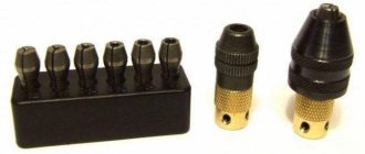
Collet chucks
The main working element of the collet chuck is a sleeve with several axial slots that divide it into petals, which, depending on the diameter of the workpiece, can be three, four or six. Such petals play the role of cams that compress the part that is inserted inside the sleeve. Collets are available as feeding and clamping. The feed collet is a hardened steel sleeve with three partial cuts that form petals with their ends pressed together. Solid clamping collets are made in the form of a bushing with spring-type petals.
Adhesion increases due to the narrowing of the slots during the procedure of pressing the collet into the cartridge with the conical part. From a technical point of view, the design of a lathe chuck with a collet has some advantages over other clamping devices - for a part that is fixed in a collet, the radial runout of the product is so insignificant that they can easily be ignored. The primary area of use for such chucks is clamping cylinders, short bars or bushings for processing. They are also used for fixing cutters, drills, wrench tips and taps. Collet chucks are popular for secondary clamping of surface-machined workpieces. If the profile of the workpiece does not match the shape of the collet hole, it is customary to use replaceable inserts.
Lever chucks
Lever chucks can be used in small-scale production because their changeover procedure is simple and can accommodate workpieces in a wide range of diameters. On the centering surface in the cartridge body there is a disk, on the side of which there is a thread along an Archimedean spiral, a conical gear rim is cut on the other side. The workpiece is secured in a lever lathe chuck by a hydraulic drive, which moves the rod with the coupling. The rods with crackers, which form a double-armed lever, are capable of rotating around the center of the cylindrical section of the cracker, moving the sliders with cams to the center and clamping the workpiece. Changing the lever chuck is simple and comes down to simultaneously moving all the jaws to the required radial position using a key.
This operation takes no more time than the procedure for securing the workpiece in a three-jaw chuck, which has a non-mechanized drive. Due to the moving elements that are provided in the drawings of lathe chucks and connect the slides to the main cams, errors in the centering of the workpiece are significant, so lever chucks are used mainly in roughing operations.
Wedge cartridges
Wedge chucks demonstrate higher accuracy of workpiece centering than lever chucks. The workpiece is secured using a pneumatic or hydraulic drive, which is located at the rear end of the flat spindle. The three main cams and the cams that are associated with them, during the axial movement of the wedge, move in the radial direction and clamp the product.
For CNC machines where a large batch of parts is processed, it is important to be able to quickly assemble the lathe chuck and change the chuck to a different diameter of the workpiece being fixed, which lasts no more than 2 minutes. For machines with GPS and CNC, chuck designs are being developed with automatic readjustment to a certain diameter of the workpiece. The use of high-quality heat-treated steel for the manufacture of main parts increases the reliability, durability and accuracy of the chuck.
Diaphragm cartridges
The highest accuracy of centering of parts is ensured by the diaphragm cartridge. Elastic membranes are attached to the cartridge flange with bolts. Such a membrane has from 3 to 8 cams with replaceable jaws. Some designs of diaphragm cartridges have cams that are bolted to the diaphragm. The workpieces are installed all the way into the unclenched jaws with their butts on the pins, the pneumatic drive is turned off, the membrane tries to return to its original state and clamps the workpiece with the jaws.
The large number of jaws on the diaphragm lathe chuck helps center the workpiece with an accuracy of 0.05 millimeters or better. Due to the low workpiece holding force, such chucks are used in finishing operations with a small cross-section of the chips being removed. When installing workpieces into a diaphragm cartridge, the pneumatic drive is used exclusively to open the jaws, so operations with such a cartridge are safe. In the event of a sudden decrease in pressure in the network during processing, the workpiece is still securely held in the chuck by the elastic forces of the membrane.
Three jaw chucks
Chucks that have three radial grooves have such a characteristic feature - centering, which occurs simultaneously with the workpiece being secured. The jaws move in a spiral synchronously under the action of a force that is applied at one point using a socket lever or key, depending on the transmission mechanism used in the design of the chuck.
The design of a three-jaw lathe chuck uses different types of jaws. Straight ones are installed in the groove outward in steps, and the part is clamped from above by the internal surfaces or the outer surface of the steps along the inner surface of the product. Reverse jaws are arranged in steps toward the center and are used for clamping workpieces with large diameters. The jaws are marked with a serial number, which must be followed when installed in the chuck.
Four jaw chucks
Four-jaw chucks are characterized by the presence of four grooves that are radially directed, into which the clamping jaws are installed. For the movement of each cam, a separate mechanism is provided in the design of the chuck, which makes it independent of the movement of the others. The purpose of a four-jaw wood lathe chuck with independent jaws is to secure and hold when processing workpieces with a non-cylindrical shape, or when the axis of the cylindrical surface that is being processed does not coincide with the fastening axis.
The cams are installed in reverse and forward positions. The reverse position is used if you need to clamp a workpiece with a large cross-sectional area. Four-jaw self-centering chucks are also used to secure rods that have a square cross-section.
Now you can safely give your preference to one of the varieties of lathe chucks. It is recommended to be guided primarily by the environment in which the products are used, the material and shape of the workpieces that will be secured using a lathe chuck.
Materials used:
- JSC "Grodno Lathe Chuck Plant "BelTAPAZ" https://beltapaz.com/
- https://strport.ru/instrumenty/vybor-i-vidy-tokarnykh-patronov
Drive cartridges with a sunken center
Drive chucks with a sunken center are designed for fastening parts on the outer untreated surface with simultaneous centering by the supplied center 1. By applying pressure to the part, the center is insulated and ensures that its end reaches the stop against the base surface of the nut 2.
The center is locked when clamped automatically by cams 5, which impart rotation to the nuts 4 and sliders 5 (relative to the axis of the chuck). Thanks to the inclined grooves, the sliders are imparted translational movement along the axis of the grooves. In this case, the crackers move along the inclined grooves and send the cams all the way to the nut 2.
| D | clamp d | H | |
| max | min | ||
| 170 | 50 | 10 | 70 |
| 220 | 70 | 20 | 90 |
Related Pages
- Diaphragm cartridges and mandrels
- Solid conical mandrels
- Mandrels and plugs for installation and fastening of workpieces on the external machined surface
- Mandrels and plugs for installation and fastening of workpieces on the internal machined surface
- Mandrels and plugs for installation and fastening of workpieces on the internal untreated surface
- Mandrels and chucks for fastening workpieces on a threaded surface
- Rotating centers
- Machine vice
- Machine tables
- Machine stands
- Dividing devices for machine tools
- Conductors and stands for overhead conductors
- Gripping devices for automatic lines
General design and arrangement of a lathe chuck for a metal machine
The following kits are supplied with the cartridge:
- straight cams;
- reverse cams;
- Cam racks are supplied outside the kit.
The most common is the three-jaw chuck, consisting of:
- monolithic or composite body with three radial grooves for cams;
- cams (direct and reverse) are made of high-quality hard, hardened steel of high strength, connected to the end thread of the spiral disk;
- spiral disk, with a large gear on its reverse side. Associated with the bevel gear gear;
- bevel gears, by rotating a key inserted into the square hole of this gear, a rotational movement is imparted to the spiral disk.
The simplicity of technological methods for basing parts has become the reason for the popularity and spread of the three-jaw chuck on machines used in production
Key
A metal rod, at one end of which a hole is drilled perpendicular to its axis with a metal lever installed in it. Exceeding the length of the lever by 35–40% relative to the height of the key is optimal.
At the lower end of the rod there is a tetrahedral tip, commensurate with the hole inside the bevel gear. Serves as a manual drive of the cams by rotating the spiral disk while securing the workpiece in the working area of the machine.
Spring
Installed on the tip of the key. Upon completion of the operation, the load from the efforts of the hand on the key is removed and the spring, straightening, removes the key from the cartridge socket. If the machine operator inadvertently does not remove the key himself, then the spring does it for him.
Sleeve
A hollow cylinder, in the upper part of which grooves are cut for half-ring crackers. Provides fixation of the bevel gear in the working body of the cartridge. The upper part of the bevel gear with a groove for half-ring crackers is installed in the inner diameter of the bushing.
Gear
The bevel (or small) gear is inserted into the small hole in the chuck body. Its upper part is connected to the grooves of the bushing by means of half-ring crackers.
The small gear is constantly meshed with the teeth of the large gear and is designed to transmit rotational motion to the helical disk of the chuck.
Flange
Adapter flange, faceplate. Designed for a strong and precise connection of the chuck with the working end of the machine spindle. For example, a thread is cut on the TV-4 spindle, an adapter flange (faceplate) is installed on it, onto which the lathe chuck is attached.
Spiral disk
Archimedes spiral, snail, planetary. A metal disk with large gear teeth on one side that are permanently meshed with the bevel gear gear.
On the other side of this disk, a spiral profile is cut out, which is in constant contact with the grooves (racks or combs) of the cams. The latter, moving synchronously, work to clamp, center and fix the part in the processing area of the machine.
The part clamped by the cams is removed by rotating the chuck key in reverse.
Reverse cam
Used for clamping large diameter parts. Each cam has two stages for fastening parts for expansion and one prism for compression.
Cam stages are used to eliminate end runout of the part. In addition, machine operators independently create an additional fastening base on the return cams that works to expand.
Frame
Depending on the design and methods of attachment to the spindle, it can be conditionally divided into monolithic (the body is one basic part) and composite, in which the body is divided into two basic parts:
- Monolithic with a cylindrical belt. It is attached to the spindle through an intermediate flange according to special GOST. Made from high-quality steel and less often from cast iron.
- Composite body. The base part is divided into two components:
- the front part or body (sometimes the front semi-body), it contains a spiral disk and slots for the cams;
- the rear part or flange (often the rear half-body), which houses bevel gears.
Top jaws
They are mounted on the cam rails of the lathe chuck. They are made from unhardened steel grades and are called “raw cams”. Designed for fastening large diameter parts.
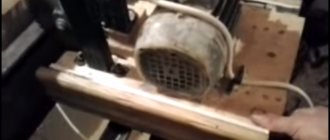
DIY vacuum chuck for wood
If your lathe's headstock spindle has a through hole for knocking out the gear center, you can add a homemade vacuum chuck to your arsenal. For this you will need:
- Powerful vacuum cleaner
- Closed bearing, approximately equal in outer diameter to a vacuum cleaner hose
- A piece of thick rubber hose for connecting the vacuum cleaner and the bearing
- Clamp
- Standard faceplate with hole in the center
- A small piece of MDF or thick plywood
- Textolite for adapter
A bushing is machined from the textolite, one side of which should be equal in diameter to the internal size of the bearing, the other - to the spindle. This homemade adapter is pressed into the bearing using glue; it will be held in the machine due to the tightness of the fit. The resulting structure is connected with a piece of hose to the vacuum cleaner and secured with a clamp.
A disk is cut out of MDF or plywood, attached to a faceplate and ground. It is better to make the surface slightly concave. To ensure a tight fit, linoleum or thin rubber is glued on top. The disk is drilled through the center to remove air. A similar self-made chuck provides a pressing force of 40 - 50 kg, sufficient to hold medium-sized parts during finishing.
State standards regulating the design and dimensions of lathe chucks
- GOST 1654 - General purpose lathe chucks. General technical conditions
- GOST 2571 - Drive lathe chucks. (for spindles according to GOST 12593-72 and GOST 12595-85)
- GOST 2675 — Self-centering three-jaw lathe chucks. Main Dimensions
- GOST 14903 — Self-centering two-jaw lathe chucks
- GOST 24351 — Self-centering lathe chucks 3- and 2-jaw wedge and lever-wedge
- GOST 24568 - Magnetic cartridges. Specifications
- GOST 3890 - Four-jaw chucks with independent movement of the jaws
- GOST 16157 — Membrane chucks for grinding holes in gears
State standards regulate the operational and technical parameters according to which lathe chucks for machine tools are selected:
- A number of possible outer diameters of chucks and, accordingly, a range of workpiece sizes: maximum and minimum diameter (outer and inner), depending on the method of fastening - on direct or reverse cams. The maximum permissible weight of the workpiece is taken into account;
- Method of attaching the chuck to the spindle. Connecting dimensions: diameter of the centering belt or centering cone;
- Location and dimensions of mounting holes in the lathe chuck;
- Limits of turning speed of the lathe chuck;
- The diameter of the hole in the chuck body for installing a rod or pipe;
- Lathe chuck accuracy
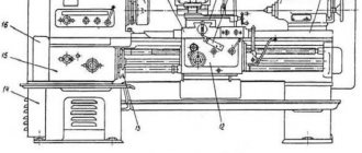
Workpiece processing scheme
Figure No. 1. Scheme of part processing. Designation of device elements: 1 - drive cartridge; 2 – fastening leash-clamp; 3 – fixing bolt; 4 – movable steady rest; 5 – product being processed.
Lathe driver chucks used in turning work are made in the form of a disk with four grooves and a threaded bushing having identical dimensions to the headstock spindle. When using a straight clamp, a movable pin is installed in the cartridge, fixed with a nut in the groove of the fastener. When processing the workpiece, the pin rests against the tail of the clamp. The cartridges used must comply with GOST 2571-71, GOST 13364-67, GOST 1435-99 and GOST 25557-2006 for all established parameters.
Download GOST 2571-71 “Drive-type lathe chucks”
If a curved clamp is used during a turning operation using a lathe, the pin is not used, since the tail of the clamp is installed in the groove of the locking element.
Drawing No. 2. Drive chuck design. Designation: the main elements that make up the fastening element of the workpiece being processed.
This design has protruding parts, which allows the possibility of injury to the specialist processing the product. To eliminate the possibility of injury, a closed cartridge is used, made in the form of a casing with a boss and a threaded sleeve identical to the open element. The clamp is hidden inside the casing, which ensures safe work.
Drawing No. 3. The design of the driving chuck, made with a closed body. Designation of elements: 1 - cap with tide; 2 – outer sleeve; 3 – clamp.
Fastening elements that do not provide for the use of a clamp are also used. In order to speed up the processing of products, instead of clamps, front centers are used, which simultaneously perform two operations: centering the workpiece and acting as a leader (Drawing No. 4). When the product is exposed to the rear center, the corrugated notches are pressed more tightly to the sides of the part and impart a rotational movement to it. When turning hollow products, external grooved centers are used, and when using rollers, internal grooved centers are used.
Drawing No. 4. Fixing the workpiece using a driving chuck. Designation: 1,2 – centers.
The workpiece to be processed is supported on the center, and the cams are used to transmit rotation to the workpiece. Moreover, the cams are made floating for more complete fixation of the part. The mandrel is fixed using the clamping force acting between the tailstock and the front center of the lathe mechanism, which moves to the left, as a result of which the cams take the optimal position and fix the workpiece more tightly. The conical support ring has a gap, which allows it to occupy a middle position due to springs. Rotational movements of the workpiece are ensured by cams with a grooved surface.
Safe and dangerous leash cartridges
Is it possible to make the part yourself?
Of course, making a full-fledged faceplate yourself will be extremely difficult, and even in some cases, too expensive, but there are options that you can make yourself without much expense. They won't fit all the pieces, but they can secure the basic pieces.
Preparation of the faceplate
Apply the parameters you need to the beam. Using a compass, mark a diameter slightly larger than the central hole. This is necessary so that when gluing you do not “eat” a few extra millimeters and make the part smaller than necessary.
Coat the parts you are going to glue with hot glue, stepping back a centimeter from the edge. Hold the parts properly so that they finally stick together.
To make it you will need:
- Tools: Lathe, cutters, plumbing kit, earplugs/earphones for shooting, shield, inverter and all its accessories, electrodes (2.5 mm), hot melt glue, machine.
- Details: Nuts, washers, dry birch firewood. Cut the extended nut in half with the machine running.
Next, take the body washer. Make sure the nut doesn't fall through. Place the nut with its ribs in the center of the washer. Weld half of the nut to the washer, welding first one side and then the other.
When the part has cooled, beat the glass crust and place it on the spindle. Drill several holes on the faceplate; they will help secure large objects in the future.
Next, paint the part before it gets rusty. For example, you can coat the bottom of the piece with ocher. Glue newspaper onto the disc and sanding paper on top. At this point your part is ready.
Typically, faceplates are sold in sets and have a relatively low price, but for those for whom buying a whole set may hurt their wallet, there are separate kits that contain 2-3 parts, including the faceplate itself:
- Faceplate 160 mm (lathe) - 2,500 rub.
- Faceplate for a screw-cutting lathe - 10,000 rubles.
- Chuck + faceplate - 14,000 rub.
- Faceplate 126 mm (from the manufacturer Record Power) - 3,400 rub.
- Chuck flange for installation - RUB 2,300.
- Set of clamps -1,700 rub.
- Faceplate for four-jaw chuck -2,700 rub.
Having disassembled such a number of faceplates, we can conclude how useful their use is when working with the machine. Of course, a faceplate, and even more so a professional faceplate, is not a cheap pleasure, but the result and quality justify the money spent.
Of course, if you are a fan of experiments, making a faceplate yourself is not difficult!
Three jaw chucks
The most common chucks are three-jaw chucks. They are installed on all turning equipment: in home workshops, garages, repair shops, small- and large-scale production.
The most common are 3 types of self-centering chucks:
- spiral:
- rack and pinion;
- eccentric with worm gear.
Three-jaw chucks are equipped with a traction (clamping elements are connected to a hydraulic or pneumatic drive) or a built-in drive. Up to thirty percent of auxiliary time is spent on clamping the workpiece during operation, so the devices are mechanized and reduce the time for installing the product. The most widely used in large-scale and mass production are powered jaw chucks with pneumatic drive. The hydraulic drive is rarely used and is used in situations where it is necessary to maintain small dimensions of the structure. The main advantage of mechanized units is speed and constant clamping force on the jaws.
Detailed video on clamping turning units
Spiral cartridges
3-jaw scroll chucks have been around for over 100 years and, due to their simple design and reliability, are still used in new equipment today. They provide a large range of cam travel and have high efficiency; it is possible to clamp eccentric and non-round workpieces. The disadvantages are rapid loss of accuracy and accelerated wear. The loss of initial accuracy occurs as a result of technological features: the volute is only improving and has low hardness, therefore, it quickly wears out - rapid wear of the centering mechanism occurs. Accelerated wear occurs due to chips and dirt getting into the wedge-shaped gaps between the teeth of the cams.
Used in single and small-scale production. Equipped with direct and reverse cams.
Rack chucks
3-jaw rack chucks get their name because of the principle of operation: a gear rim moves the racks, which simultaneously moves the jaws. More durable than spiral ones, because It is possible to harden and grind the teeth. The body is made of cast or forged steel, the remaining moving parts are alloyed, followed by hardening. They are universal and are used in single or small-scale production.
Advantages:
- stronger clamp;
- greater accuracy;
Flaws:
- Efficiency is lower than that of spiral ones;
- Possibility of clamping from only one position;
- complex design.
Eccentric chucks
3-jaw eccentric chucks are used in large-scale production. All parts of the unit are made of wear-resistant steels, and then undergo hardening and grinding. They have high precision and clamping force. They can be re-adjusted to clamp another part relatively simply - by rearranging the mounted cams.
Drive chuck
Double-jaw drive chucks are normalized (MH 4051 – 62); they can have a floating (spring-loaded) center.
A rapidly rotating drive chuck with a clamp can in some cases cause injury.
| Protective cover used when working with a driving chuck. |
A rapidly rotating drive chuck with a clamp is a source of increased danger and can cause injury.
The pneumatic lever driving chuck is used to secure and rotate workpieces mounted on centers.
The pneumatic lever driving chuck is used to secure and rotate workpieces mounted on centers.
A conventional universal drive chuck is shown in Fig. Under the influence of cutting forces, the workpiece rotates in a clockwise direction and the cams firmly jam the part. As the torque increases, the jamming, and therefore the clamping force, increases.
| Double jaw driver chuck with eccentric replaceable jaws, automatic action.| Chucks with two-jaw drive and sunken centers (dimensions in mm. |
Such leash cartridges, depending on their diameter, can accommodate loads with a total weight of 3 to 6 kg. Then, for example, with m – 3 kg, g 45 mm, n – 500, 1000, 2000 rpm, the centrifugal force pressing the cams to the workpiece will respectively be Rc 34, 138, 552 kgf.
Re-adjustable driving chuck designed by the Odessa Precision Machine Tools Plant. The changeover of the chuck is carried out by moving the strips 2 relative to the bushings 3 towards the center or away from the center of the chuck. The position of the strips is fixed with washers 7 and screws.
The adjustable pin driver chuck designed by NIIPTMASH (Kramatorsk) is intended for installation of workpieces such as shafts with diameters of 80 – 240 mm. The pointed pins can be reinstalled in the housing 8 along different circles depending on the diameter of the workpieces. Replaceable covers 10, fixed to the body 8, have corresponding oval holes that fit into the flats of the pins 9 to prevent them from turning. The pins 9 rest with their spherical ends on the spherical heel 6 mounted on the thrust bearing 5, which ensures self-alignment of the pins along the end of the workpiece. The extension of the floating center 11 and the adjustment of the spring force are carried out by rotating the glass 3 using the flats provided for this purpose. When installing the workpiece in the centers, the rotating center of the tailstock presses the workpiece in the axial direction and the pins cut into the end of the workpiece to the same depth, regardless of the non-perpendicularity of the end of the workpiece relative to its axis.
| Machining parts on rigid and floating front centers. |
The use of a drive chuck with a clamp is associated with a number of disadvantages.
The use of drive chucks eliminates the need to use clamps, which saves time on installing and securing the part and eliminates the possibility of vibration of the part during processing. In type A cartridges, cheeks 3 are mounted on plate 2, set to the size of the square end of the center mandrel. In type B chucks, driving cams 4 are installed to clamp raw parts.
The use of a driving chuck instead of a conventional clamp creates the opportunity to increase the rigidity of the installation of the shafts being turned. The workpiece, wedged between two eccentric cams, is, as it were, one whole with the moving part of the chuck. However, the presence of guaranteed gaps in the chuck mates (not selected when securing the workpiece) significantly reduces the rigidity of the entire system as a whole. Due to these gaps, the resemblance to a hinged support is maintained, since it remains possible to rotate the workpiece at a small angle.
Six-jaw self-centering chuck Soviet patent 1982 according to IPC B23B31/16
I
The invention relates to machine tool construction and can be used to secure thin-walled parts.
Six-jaw self-centering chucks are known, containing a 1st housing, main and additional cams located in the grooves of the housing, main and additional spiral disks that move these cams and are connected to the main and additional bevel wheels rotated by means of a drive bevel gear 1.
The disadvantage of the known devices is that they fasten only those parts that have strictly concentric outer and inner base surfaces.
The purpose of the invention is to expand technological capabilities and reduce clamping and releasing time.
This goal is achieved by the fact that the cartridge is equipped with a spring-loaded slider installed with the possibility of rotation around the axis of the cartridge in an arc groove made in the body, carrying a drive bevel gear, and a cross-shaped clutch placed with an additional spiral disk and an additional bevel gear, spring-loaded in two mutually perpendicular directions relative to the gear and
10 disks.
In fig. 1 shows a cross-section of the cartridge; Fig. 2 - section A-A in Fig. 1; in fig. 3 - view along arrow B in Fig. 1.
15
In the cartridge body 1 there are three evenly spaced radial grooves 2, in which the main 4 and auxiliary 5 clamping cams are placed movably along the guide 3.
20 By means of racks 6, the main cams 4 interact with the main spiral disk 7, on which the teeth of the wheel 8 are cut. By means of racks 9, auxiliary cams 5 interact with the auxiliary spiral disk 0, between the turns of which and the teeth of the racks a gap is formed, allowing the disk to move relative to cams On the disk 10 there is a key 11, movably installed in the groove of the cross coupling 12 (Oldheim coupling). Perpendicular to the indicated groove, the cross coupling is fitted with a key 13, movably installed in the groove of the auxiliary bevel gear 14. With two springs 153 located in the recesses made in the key 11 and in the body of the coupling 12, the auxiliary disk 10 is fixed coaxially with the coupling 12, and with two springs 16, located in the recesses made in the key 13 and in the body of the wheel 4, the coupling 12, and therefore the disk 10, is fixed coaxially with the cartridge body 1. The bevel wheels 8 and 14 interact with the drive bevel gear 17 (one or more), which is rotatably mounted in the slider 18, mounted movably in the arc groove 19, made on the periphery of the housing 1. The carrier 20 interacts with the slider, which is mounted rotationally on the hub 21 shank 22 cartridges. The hub 21 and the shank 22 are equipped with holders 23 and 24, in which the ends of the spiral spring 25 are fixed, made with a very flat characteristic. Pruzkina 25, together with the carrier 20 and the slider 18, provide fixation of the gear 17 in its original position, which is shown in Fig. 2, The cartridge works as follows. Product 26, which is a bushing with thin walls, is installed between the separated cams 4 and 5. Using a key (not shown), gear 17 is rotated in the direction of arrow B (clockwise). Driven by gear 17, wheels 8 and 14 and with them spiral disks 7 and 10 rotate in opposite directions, bringing cams 4 and 5 closer to each other. Product 26, when the cam Kat-sh 4 reaches its surface, is installed coaxially with the chuck and resists the further movement of the cams 4 towards the axis of the chuck. As a result of this reaction, a frictional force arises between the spiral turns of the disk 7 and the teeth of the rack 6 of the cams 4, as a result of which the torque on the gear 17 increases and a reaction occurs from the side of the wheel 8, directed in the direction of arrow G. The change in the indicated reaction in the magnitude of the elastic force of the spring 25 destabilizes the initial the position of the gear 17 and it, compressing the spring, will begin to roll planetarily along the stopped wheel 8, as a result of which the movement of the cams 4 towards the axis of the cartridge will stop, and the rotation of the wheel 14 and disk 10 will accelerate, and thus the movement of the cams 5 and the inner surface of the product will accelerate. If there is an eccentricity in the location of the hole in the product or if the product has different thicknesses, one of the cams 5 comes into contact with its surface and thereby forces the cross coupling 12, together with the disk 10 and the other two cams coupled to it, to move parallel to themselves and self-align on the surface of the product about Termination movements of cams 4 and 5 stabilizes the position of the drive gear 17 and, as it continues to rotate with the key, forces wheels 8 and 14 to rotate counter to each other, while activating a clamping force between the cams, which closes on the metal of the product without causing its deformation. The product is unfastened by rotating the gear 17 counterclockwise, and when the force on the product disappears, the spring 25 will return the carrier 20, the slider 18 and the gear 17 to their original position on the stop. The centering force of a thin-walled product is regulated by the elastic force of the spring 25, which eliminates the subjectivity of centering, and at the same time the possibility of pinching and the occurrence of defects. The automatic release of the product by an auxiliary centering mechanism ensures high-speed performance, increasing productivity regardless of whether the surfaces of the product are concentric or not. These design features provide technological
feasibility and
economic profitability
Claim
A six-jaw self-centering chuck containing a housing, main and additional cams placed in the grooves of the housing, a main and additional spiral disks moving said cams and connected to the main and additional bevel wheels rotated by means of a drive bevel gear, characterized in that, with a view to expanding technological capabilities and reduction of clamping-unclamping time, the chuck is equipped with an installation with the ability to rotate around the axis of the chuck in an arc groove made in the body with a spring-loaded slider carrying a drive bevel gear, and a cross-shaped clutch placed between the additional 1st spiral disk and the additional bevel gear, spring-loaded in two mutually perpendicular directions relative to the gear and disk.
Sources of information taken into account during the examination
1о Copyright certificate of the USSR No. 379331, class. B 23 B 31/61, 1972.
What other GOSTs are associated with lathe chucks?
For various turning parts for metalworking machines, their own standards have been developed that fix all the necessary parameters. Main GOSTs:
- GOST 24351-80 For self-centering three- and two-jaw wedge and lever-wedge elements.
- Standard 3890-82 For four-jaw parts with independent movement of the jaws" indicating the main and connecting dimensions.
- 14903-69 For self-centering two-jaw elements.
- Gosstandart 2848-75 Tool cones. Tolerances. Methods and means of control.
- Gosstandart 12595 – 2003 – metal-cutting machines.
- State Standard 3889 – Flanges for self-centering chucks.
- Standard 12593-72 – spindle flange dimensions
All this technical documentation allows us to summarize and classify the varieties of these basic elements of turning equipment.
Three-jaw options with a diameter of 250 mm are most often used in lathes, both at the industrial and domestic levels. Therefore, the standards for their production in all respects must be strictly observed.
The document regulating self-centering spiral rack elements contains detailed dimensions, as well as separate diagrams and drawings of this part, from which it is possible to determine compliance with the declared data. At the slightest violation of the parameters specified in GOST, the quality of the working process of the lathe is significantly reduced.
Intermediate flanges for self-centering cartridges GOST 3889-80
This standard applies to intermediate flanges intended for installation on the ends of spindles of metal-cutting machines with self-centering general purpose chucks.
Intermediate flanges (they are also called plan washers) are necessary for centering and fastening chucks with a centering belt (GOST 2675 type 1) on any of the 4 types of lathe spindle ends.
GOST 3889-80 (DIN 6350) Flanges must be manufactured in the following versions:
- Version 1 – installed on the threaded ends of spindles in accordance with GOST 16868;
- Version 2 – installed on the flanged ends of spindles in accordance with GOST 12593 under a rotary washer;
- Version 3 – installed on the flanged ends of spindles in accordance with GOST 12595 version 1;
- Version 4 – installed on the flanged ends of spindles in accordance with GOST 12595 version 3.
GOST 3889 Version 1. Intermediate flanges for threaded ends of spindles
GOST 3889 Intermediate flanges for threaded ends of spindles
GOST 3889 Intermediate flanges for threaded ends of spindles
In order to secure a lathe chuck at the front end of the spindle, it is necessary to make or purchase an intermediate (adapter) flange, which is also called a faceplate.
From the spindle side, the intermediate flange must be screwed onto the spindle thread d and very accurately slide onto the centering belt - a cylinder with a diameter of Ø d1 and a length of l mm.
On the side of the lathe chuck, the intermediate flange must have a centering belt - step D4 for precise installation and centering of the lathe chuck on the intermediate flange, and also have through holes for attaching the chuck. Obviously, for each standard size of lathe chuck there must be its own intermediate flange.
It is allowed to install 1 locking device against self-unscrewing on the intermediate flange of the design.
The lathe chuck installation process consists of the following steps:
- The intermediate flange is screwed onto the spindle thread until it stops. The hole in the flange should fit tightly onto the spindle collar
- The screws of the locking device are tightened against self-unscrewing
- Check the runout of the centering belt on the flange (D1) and the supporting end surface on the chuck side
- A cartridge is installed on the centering belt (D1) and secured with bolts
- The radial and axial runout of the chuck is checked
Example: intermediate flange for a TV-4 lathe
Intermediate flange for TV-4 lathe
An example of a designation for a flange of version 1, with a diameter of 100 mm:
Flange 7081-0592 GOST 3889-80
An example of a designation for a flange of version 1, with a diameter of 125 mm:
Flange 7081-0593 GOST 3889-80
Intermediate flange for a lathe with a threaded spindle end
Intermediate flange for a lathe with a threaded spindle end
GOST 3889-80 Intermediate flanges for rotary washer
GOST 3889-80 Intermediate flanges for rotary washer
GOST 3889-80 Intermediate flanges to the ends of spindles type A. Version 1
GOST 3889-80 Intermediate flanges to the ends of spindles type A. Version 1
Classification of lathe chucks
There are several types of classifications: according to the number of cams, type of clamp, fixation mechanism, type of execution, accuracy class.
By the number of jaws in the chuck
Cams are responsible for the quality of fastening of parts. They are made of high quality metal.
Double cam
Options secure asymmetrical parts that are not processed. But they are also used for standardized workpieces.
Four-jaw
The 4 jaw chuck consists of four units that function independently. Used for processing rectangular and square options.
By type of workpiece clamp
The chuck jaws are divided into direct and reverse. Virtually no effect on performance. Selected depending on the type of cartridge input.
The clamping occurs externally. The cams are located on top and grab the part.
Reverse
Clamping occurs from the inside, from the inside. The object being processed is chosen to be hollow, so that it can catch on.
According to the workpiece fixation mechanism
The fixation mechanism is an important characteristic that determines the quality of work.
Wedge
Fastening occurs using three cams on a straight platform. Wedge variations are used for digitally controlled equipment.
Collet
There are no standard clamps. Their role is played by bushings with pliers (up to six pieces). Can be used on standard mechanical machines.
Lever
The part is processed by moving the mechanism with a lever. Quite a costly and lengthy process. Used to work with special, complex textured parts.
Drilling
The parts are secured by the pressure of the wrench. The principle of operation is similar to the operation of a drill, only in the opposite direction.
Thermal cartridges
An extraordinary look, which is practically not used in machines made in Russia. For fastening, the hole is heated, and for removal, too.
Hydraulic chucks
The mechanism is the same as the previous one, but not temperature is used, but the hydrosphere. The liquid medium additionally dampens vibrations.
Self-clamping
Such options are practical. The design includes clamps that are tightly fixed to the workpiece independently.
Jaw chucks
The most convenient and functional. They work both in compression and expansion, so they can grip the workpiece both from the outside and from the inside. They differ in the number of cams and their drive mechanism. Unlike metalworking, two- and three-jaw chucks are practically not used for turning wood. Options with a spiral drive and non-removable cams are also not popular. The most common type of lathe chuck for woodworking is self-centering four-jaw, with a rack-and-pinion transmission mechanism and replaceable jaws. They are supplied to the Russian market by the brands Axminster, Jet, Barracuda and other, less well-known companies.
Jaw lathe chuck
4-jaw lathe chuck Ø150 mm
4-jaw lathe chuck Ø100 mm
Types of cams
According to their shape and purpose, replacement jaws for wood lathe chucks are divided into several types, which have special markings:
- A, G, M – for compression, differ in size and depth of grip;
- D and F – act on unclenching;
- C and H are universal. Different shapes of sponges;
- To work with soft, compression-sensitive wood, cams with rubber fastenings are used.
Classification of lathe chucks
There are several types of classifications: according to the number of cams, type of clamp, fixation mechanism, type of execution, accuracy class.
By the number of jaws in the chuck
Cams are responsible for the quality of fastening of parts. They are made of high quality metal.
Double cam
Options secure asymmetrical parts that are not processed. But they are also used for standardized workpieces.
Four-jaw
The 4 jaw chuck consists of four units that function independently. Used for processing rectangular and square options.
By type of workpiece clamp
The chuck jaws are divided into direct and reverse. Virtually no effect on performance. Selected depending on the type of cartridge input.
The clamping occurs externally. The cams are located on top and grab the part.
Reverse
Clamping occurs from the inside, from the inside. The object being processed is chosen to be hollow, so that it can catch on.
According to the workpiece fixation mechanism
The fixation mechanism is an important characteristic that determines the quality of work.
Wedge
Fastening occurs using three cams on a straight platform. Wedge variations are used for digitally controlled equipment.
Collet
There are no standard clamps. Their role is played by bushings with pliers (up to six pieces). Can be used on standard mechanical machines.
Lever
The part is processed by moving the mechanism with a lever. Quite a costly and lengthy process. Used to work with special, complex textured parts.
Drilling
The parts are secured by the pressure of the wrench. The principle of operation is similar to the operation of a drill, only in the opposite direction.
Thermal cartridges
An extraordinary look, which is practically not used in machines made in Russia. For fastening, the hole is heated, and for removal, too.
Hydraulic chucks
The mechanism is the same as the previous one, but not temperature is used, but the hydrosphere. The liquid medium additionally dampens vibrations.
Self-clamping
Such options are practical. The design includes clamps that are tightly fixed to the workpiece independently.