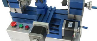
To expand the functionality of the lathe, it is recommended to use special milling parts. They are manufactured in a variety of variants, which makes it possible to perform a variety of tasks in the field of parts processing. Milling fixtures for a lathe come in several types; the complexity of their design depends on the characteristics of the task at hand.
Modern equipment is head and shoulders above Soviet analogues; the metal used in the construction is of high quality, strength and durability. The fasteners of the unit have quality certificates and are also durable.
To carry out work on such a unit, craftsmen require a specialized medical examination; the equipment requires attentiveness, scrupulousness, and good vision from the specialist. The finishing process of any metal fragment takes place in several stages.
Types and purpose
The device for a metal lathe is manufactured in three varieties:
- The first option is special. With its help, the operational capabilities of the unit are increased.
- The second option of additional parts is used to fix the tool.
- Thanks to the use of the third option of equipment, parts that are to be processed on a lathe are fixed.
Using various equipment, a wide range of work performed by the turning unit is provided:
- metal fragments are fixed qualitatively;
- the accuracy of processing metal workpieces increases;
- it becomes possible to perform milling operations correctly;
- The process of processing metal parts is accelerated.
The milling fixture for a lathe is manufactured in factories. It is characterized by a high level of strength, this feature ensures its long-term use.
Thanks to the use of high quality materials for the manufacture of equipment, its service life is significantly extended. At home, it is easy to use a homemade device for a metal lathe. Most often, a special attachment is used, thanks to which craftsmen can perform the following operations:
- mill planes;
- select grooves and grooves;
- process the base using face and end mills;
- contour processing of various products.
Milling attachment for a lathe
An attachment for a lathe makes it possible not only to expand the scope of application of the equipment, but also to perform metalworking work as accurately as possible.
Turning technology and tooling
Home » Articles » Professionally about metalworking » LathesWe recommend purchasing:
Installations for automatic welding of longitudinal seams of shells - in stock!
High performance, convenience, ease of operation and reliability in operation.
Welding screens and protective curtains are in stock!
Radiation protection when welding and cutting. Big choice. Delivery throughout Russia!
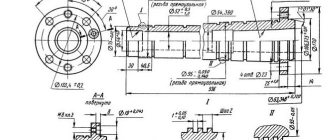
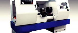
Turning is the most common cutting method and is used in the manufacture of axisymmetric parts such as rotating bodies (shafts, disks, axles, fingers, journals, flanges, rings, bushings, nuts, couplings, etc.). The main types of turning work are shown in Fig. 4.6.
Rice. 4.6. The main types of turning work (arrows indicate the directions of tool movement and workpiece rotation): a - processing of external cylindrical surfaces; b - processing of external conical surfaces; c - processing of ends and ledges; d - turning of grooves and grooves, a piece of workpiece; d - processing of internal cylindrical and conical surfaces; e - drilling, countersinking and reaming of holes; g - cutting external threads; h - cutting internal threads; and - processing of shaped surfaces; k - rolling of corrugations
In mechanical engineering, most parts receive their final shapes and overall dimensions as a result of mechanical processing of the workpiece by cutting, which is carried out by sequentially removing thin layers of material in the form of chips from the surface of the workpiece with a cutting tool.
Cutting tool
. When working on lathes, various cutting tools are used: cutters, drills, countersinks, reamers, taps, dies, threading heads, shaped tools, etc.
Turning cutters are the most common tool and are used for processing planes, cylindrical and shaped surfaces, cutting threads, etc. (Fig. 4.7).
Rice. 4.7. Turning cutters for various types of processing: a - external turning with a bent cutter; b - external grinding with a straight through cutter; c - turning with cutting the ledge at a right angle; g - cutting a groove; d — turning the radius fillet; e - boring a hole; g and h - cutting external and internal threads, respectively
Drilling is one of the common processing methods on lathes and is carried out to pre-process holes. Pre-cutting a hole in solid material can only be done using a drill. Depending on the design and purpose, drills are distinguished: spiral, feather, for deep drilling, centering, ejector, etc. Spiral drills are most widespread in turning.
The movement of the cutting tool during turning and its fastening on a screw-cutting lathe is ensured by several units (assembly units). Below is a brief description of how some of them work.
Rice. 4.8. Caliper: 1 - lower slide (longitudinal caliper); 2 — lead screw; 3 — transverse caliper slide; 4 - rotary plate; 5 - guides; 6 — tool holder; 7 — rotating head of the tool holder: 8 — screw for fastening the cutters; 9 — tool holder rotation handle; 10 - nut; 11 — upper slide (longitudinal support); 12 — guides; 13 and 14 — handles; 15 — handle for longitudinal movement of the caliper
The support (Fig. 4.8) consists of a lower slide (longitudinal support) 7, which moves along the frame guides using a handle 75 and ensures the movement of the cutter along the workpiece. On the lower slide, transverse slides (transverse slide) 3 move along guides 12, which ensure the movement of the cutter perpendicular to the axis of rotation of the workpiece. The upper slide 77 moves along the guides 5 of the rotary plate (using the handle 13), which together with the plate 4 can rotate in a horizontal plane relative to the transverse slide 3 and ensure the movement of the cutter at an angle to the axis of rotation of the workpiece. The cutter holder (also known as a four-position cutting head) is attached to the upper slide 77 using handle 9 and allows you to put the cutter into work with minimal time.
Rice. 4.9. Tool holder: 1 - washer; 2 - head; 3 - conical mandrel; 4 — handle; 5 — upper slide; 6 — four-sided cutting head; 7 - screw
The tool holder structure is shown in Fig. 4.9. A conical mandrel 3 with a threaded end is installed in the centering bore of the upper slide 5. A four-sided cutting head 6 is installed on the mandrel cone. When the handle 4 rotates, the head 2 moves down the thread of the conical mandrel 5. The washer 7 and the thrust bearing ensure a rigid fit of the cutting head 6 on the conical surface of the mandrel 3. Head 2 is attached to the cutting head 6 with screws 7. The cutting head is kept from turning when secured by a ball, which is wedged between the surfaces formed by the groove in the base of the conical mandrel 3 and the hole in the cutting head 6.
The tailstock of a lathe is primarily designed to support long workpieces during processing. It is also used to secure tools intended for processing holes (drills, countersinks, reamers) and for cutting threads (taps, dies, threading heads).
Rice. 4.10. Tailstock: 1 - body; 2 - center; 3, 6 — handles; 4 - quill; 5, 12 and 14 - screws; 7 - flywheel; 8 - traction; 9, 10 — levers; 11, 13 — nuts
The tailstock structure is shown in Fig. 4.10. In the housing 7 (when the screw 5 is rotated by the flywheel 7), a quill 4 moves, secured by a handle 3. A center 2 with a conical shank (or a tool) is installed in the quill. The tailstock is moved along the machine guides manually or using a longitudinal slide. In a stationary working position, the tailstock is fixed with a handle 6, which is connected to a rod 8 and a lever 9. The force of pressing the lever 9 with a rod 8 to the frame is adjusted with a nut 77 and a screw 72. A more rigid fastening of the tailstock is made using a nut 13 and a screw 14, which presses to bed lever 10.
On screw-cutting lathes designed for processing workpieces of complex configurations in mass production, various tools are secured in a multi-position rotary turret head. When rotating (indexing) the turret head, tools pre-set to size are sequentially put into operation.
Depending on the purpose, accessories for lathes can be divided into three groups:
- devices for securing workpieces;
- auxiliary tool for securing the cutting tool;
- devices that expand the technological capabilities of machine tools, i.e. allowing you to perform work that is not typical for these machines (milling, simultaneous drilling of several holes, etc.).
Devices for securing workpieces
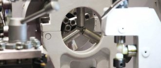
. For fastening workpieces on lathes, two-, three- and four-jaw chucks with manual and mechanized clamping drives are used.
Rice. 4.11. Three-jaw self-centering chuck: 1, 2 and 3 - jaws; 4 — disk; 5 - gear; 6 — cartridge body
The most widely used is the three-jaw self-centering chuck (Fig. 4.11). Cams 7, 2 and 3 of the cartridge move simultaneously using disk 4. On one side of this disk there are grooves (shaped like an Archimedean spiral) in which the lower projections of the cams are located, and on the other there is a cut bevel gear mated to three bevel gears 5. When you turn one of the wheels 5 with a key, disk 4 (thanks to gearing) also turns and, by means of a spiral, simultaneously and evenly moves all three cams along the grooves of the cartridge body 6. Depending on the direction of rotation of the disk, the cams move closer to the center of the chuck or move away from it, clamping or releasing the part. The cams are usually made in three stages and are hardened to increase wear resistance.
There are cams for securing workpieces on the internal and external surfaces; when fastening on the inner surface, the workpiece must have a hole in which the cams can be placed.
Three-jaw self-centering chucks hold round and hexagonal workpieces or large diameter round rods.
Various shaped castings and forgings are secured in two-jaw self-centering chucks; The jaws of such chucks are usually designed to secure only one part.
In four-jaw self-centering chucks, square-section rods are fixed, and in chucks with individual adjustment of the jaws, parts of rectangular or asymmetrical shape are fixed.
Rice. 4.12. Types of centers: a - persistent; b - reverse; c - persistent half-center; g - with a spherical working part; d - with a corrugated surface of the working cone; e - with a carbide tip; 1 - working part; 2 — tail part; 3 - support part
Depending on the shape and size of the parts being processed, different centers are used (Fig. 4.12). The angle at the top of the working part of the center (Fig. 4.12, a) is usually 60°. The conical surfaces of the working 1 and tail 2 parts of the center should not have nicks, as this leads to errors in the processing of workpieces. The diameter of the supporting part 3 is smaller than the small diameter of the tail cone, which allows the center to be knocked out of the socket without damaging the conical surface of the tail part.
Rice. 4.13. Rotating center: 1 - working part; 2, 3 and 5 — rolling bearings; 4 — tail section
When processing with high cutting speeds and loads, rear rotating centers are used (Fig. 4.13). In the tail part 4 of the center, an axis is mounted on rolling bearings 2, 3 and 5, at the end of which the working part 1 of the center is made, which ensures its rotation together with the workpiece being processed.
Rice. 4.14. Turning clamps: a - regular: 1 - screw; 2 - shank; b - self-tightening: 1 - stop; 2 - shank; 3 - spring; 4 - axis; 5 - prism
Clamps (Fig. 4.14) serve to transmit rotation from the spindle to the workpiece installed at the centers of the machine. The clamp is put on the workpiece and secured with screw 1 (Fig. 4.14, a), while the shank 2 of the clamp rests against the pin of the driving chuck.
When processing a workpiece at centers, movement can be transmitted to it by a driver chuck through a driver pin and a clamp, which is attached to the part with a screw. To reduce auxiliary time during roughing, self-clamping driver chucks are used in the centers of shafts with a diameter of 15...90 mm.
Collet chucks are used primarily for securing cold-drawn rods or for re-clamping workpieces on a pre-treated surface.
Diaphragm cartridges are used when it is necessary to process a batch of workpieces with high centering accuracy.
The method of installing and securing workpieces on the machine is chosen depending on their size, rigidity and required processing accuracy. With a ratio of l/D < 4 (where l is the length of the workpiece being processed, mm; D is the diameter of the workpiece, mm), the workpieces are fixed in the chuck, with 4 < l/D< 10 - in the centers or in the chuck with pressing at the rear center (Fig. 4.15), with l/D> 10 - in the centers or in the chuck and the center of the tailstock and supported by a rest (Fig. 4.16).
Rice. 4.15. Installation of workpieces in the chuck with pressing at the rear center: 1 - workpiece; 2 and 3 - incisors
Rice. 4.16. Lunettes: a - movable; b - fixed: 1 - upper (folding) part; 2 - screws; 3 - bolts; 4 - cams or rollers; 5 — bar; 6 - bolt with nut
The most common is the installation of the workpiece being processed in the centers of the machine.
The workpiece is processed in centers if it is necessary to ensure the concentricity of the processed surfaces when reinstalling the workpiece on the machine, if subsequent processing is performed on a grinding machine, also in centers, and if this is provided for by the processing technology.
Workpieces with holes are installed in the centers using turning mandrels (Fig. 4.17).
Rice. 4.17. Turning mandrels: a - mandrel with a small taper (usually 1:2000): 1 - center hole; 2 - clamp; 3 - mandrel; 4 - workpiece; b - cylindrical mandrel: 1 - workpiece; 2 - mandrel; 3 — pressure washer; 4 — washer; c - expanding (collet) mandrel: 1 - workpiece; 2 - conical mandrel; 3, 5 - nuts; 4 - hollow mandrel; g - spindle mandrel: 1 - collet; 2 - workpiece; 3 - expanding mandrel; 4 - cartridge; d - mandrel with an elastic shell: 1 - plan washer; 2 - bushing; 3 - workpiece; 4 — hole for introducing hydraulic plastic; 5, 6 - screw
To facilitate the working conditions of workers when securing workpieces to machines, mechanized drives are installed: pneumatic, hydraulic, electric and magnetic.
Auxiliary tool
. To install and secure the cutting tool on the machine, an auxiliary tool is used, which largely determines the accuracy and productivity of turning.
As an example, consider an auxiliary tool for turret lathes. The operating principle of this tool is common to all lathes; Only the tail part, with the help of which the tool is installed on the machine, changes. On turret lathes, cylindrical holders, prismatic holders with cylindrical shanks and holders of complex shapes with cylindrical shanks, as well as bayonet holders are used.
The stops used on turret lathes to limit the feed of a bar or the rotation of a turret head with a horizontal axis of rotation can be rigid, adjustable, or folding.
Product control operations and the measuring instrument required for this will be considered when describing the technology for processing specific elements of parts (for example, cylindrical outer surfaces, holes, conical outer and inner surfaces). There will also be technological equipment for processing these surfaces, expanding the technological capabilities of the machines of this group.
What equipment should I use?
It is necessary to select a device for a lathe in accordance with the tasks assigned to the operator. Most often, specialists use several parts.
Vibration mounts - ideal for metal lathes and grinding equipment. With its help, the quality of part processing is increased. Thanks to such a product, vibration is significantly reduced; this operating principle has a positive effect on the life of the machine.
Centers. Lathe units have a universal design, but it forces the master to use special equipment. Thanks to the centers, the highest quality setting of precision parameters is ensured.
Ammo. The device is most often used in woodworking units. Using such equipment, the most reliable fixation of the fragment is ensured. The cartridge is secured using a bolt through a clamp.
Fists. This type of part is characterized by the presence of several design options. With their help, reliable fixation of the part on the outside of the shaft is ensured.
Cam for lathe
Jaw lathe chucks - parts are used for fixing workpieces that have a rectangular, cylindrical or shaped shape. There are several types of chucks - two-jaw, three-jaw and four-jaw. The use of products with various types of turning installations is allowed.
The selection of equipment must take place after studying all the advantages of the unit, as well as analyzing the conditions of the room where the equipment will be installed. Additionally, you should determine where the cabinet with metal fragments and finished products will be placed.
Types of accessories for the machine
There are different types of lathe attachments. Accessories for lathes are produced in a wide range. This makes it possible for the master to choose the best option in accordance with the task.
Vibration mounts
Vibration mounts (aka vibration isolators) are designed for active or passive vibration isolation of different types of machines: small, medium or large. The use of vibration supports will help improve the quality of parts processing.
Centers
Lathe centers are used to fix the workpiece, which has a body of rotation on the tailstock of the lathe. The lathe center allows you to process parts at high speed and with minimal runout.
Ammo
These are devices for accurately securing a workpiece on a machine. Thanks to the use of lathe chucks, the functionality of the machine itself is significantly increased, and it also becomes possible to process complexly shaped parts. Mainly used to secure workpieces for metal cutting operations.
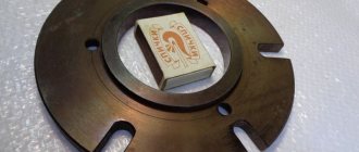
Fists
Lathe jaws can be:
- Straight - needed to clamp the workpiece from the outside for the shaft.
- Reverse - necessary for clamping the workpiece only from the inside.
- Overlays - necessary for fastening long or short workpieces of large diameters.
Typically, turning jaws are made of non-ferrous metals and steel without heat treatment.
Jaw chucks
Specialized for clamping rectangular and cylindrical workpieces.
- Two-jaw - necessary for securing complex workpieces with shaped parts. Double-jaw attachments can clamp a variety of surfaces into interchangeable jaws.
- Three-jaw chucks are one of the most common cartridges. They are installed on almost any lathe. In turn, they are divided into three types:
- Spiral.
- Rack and pinion.
- Eccentric.
Three-jaw chucks are equipped with a special drive. Three-jaw chucks with pneumatic drive are especially widespread. There is also a hydraulic drive, but it is rarely used.
- Four-jaw - used for clamping non-round and asymmetrical workpieces. The cams are self-adjusting and must be installed so that their axis coincides with the axis of the spindle. These cartridges are mainly used in repair shops.
Additional details
In addition to the basic accessories for a lathe, it is also worth paying attention to additional parts that may also be necessary for the master.
Lunettes
Additional equipment that is the main support when processing on a lathe. Most often they are needed to avoid damage to the workpiece and tool, as well as to avoid injury caused by beating due to high machine speeds.
Steady rests for a lathe are available with rolling (roller) and sliding (cam) supports. Shoes are special steady rests for grinding bearing rings.
Reference! Often, with long workpieces, it is impossible to do without a steady rest.
Tool holders
The tool holder is used to secure the cutting tool. It greatly simplifies the work and allows you to bore the holes as much as possible.
Tool holders are:
- Horizontal (along the spindle).
- Vertical (at right angles to the spindle).
- Mechanical.
- Electromechanical.
- Hydraulic.
- With servo drive.
- Two-position - allow you to fix two incisors.
- Four-position - allow you to fix four cutters on the machine at once.
- By means of a wedge block.
- VDI.
- TDC – fastening in a hole at a remote diameter of the disk.
- Simple - they have a special spherical gasket, which allows you to quickly change the cutter to the required one. The downside is that it only attaches with one bolt. It is necessary to constantly check the degree of fastening of the bolt and, if necessary, tighten the bolt completely.
- Rotary - allow you to place four incisors at once. Maximum efficiency when processing parts of complex geometric shapes. There are also rotary tool holders that carry 12 cutters at once.
- Quick-change - needed for minimal time losses when replacing cutters.
- Universal adapters - allow you to install large tools.
Turret
It is a rotary unit of the machine into which several tools are inserted. Typically, the turret has an indexing mechanism that accurately locks each installed tool as it rotates.
Rotation of the turret head and its fixation can be done either automatically or manually. Simultaneously with the turn, the speeds of the main movement and feed change.
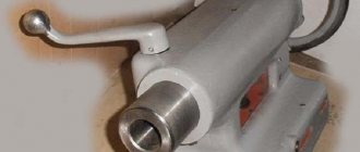
Cone ruler
The conical ruler is mounted on a carriage and is designed for processing conical surfaces. A special bracket is installed on the carriage of the machine, which is connected to this ruler using dovetail guides. The ruler can be rotated around your finger at the required angle to the axis of the workpiece. Two bolts are used to secure the ruler.
Additional details
The unit has minor, but quite important details in its design.
Lunetov. They are used in structures that process metal and wood. The scope of application of such units are milling, turning and grinding locks. The installations support long workpieces.
Tool holders. The units are used in metal lathes. Thanks to these devices, the cutters are secured to the caliper. The device has transverse and longitudinal movement in relation to the metal fragment.
Accessories for metal-cutting machines are produced in a wide range; this feature makes it possible for turners to select the most appropriate option in accordance with the tasks assigned.
The individual equipment passport always specifies the technical characteristics and departmental requirements for the operation of the installation on the territory of the enterprise. It is necessary to strictly comply with all conditions when installing the unit.
Failure to comply with safety precautions, as well as technical specifications, can lead to disruption of the technological process, as well as injuries to working personnel.
Features of using jaw chucks
The most commonly used chucks in metalworking machines are jaw chucks. In such a case, it is recommended to use two-jaw lathe devices. They are the best option if there is no need for the most precise centering.
With their use, small parts, castings, and forgings are fixed. Jaw chucks fix parts that have strictly defined geometric parameters. If it is necessary to process workpieces of arbitrary configuration, this requires the use of four-jaw chucks.
Homemade devices are characterized by the appearance of an individual drive; this design allows for the simplest possible centering.
When using chucks with such a drive, there is a chance to machine rectangular and asymmetrical parts. Square bars are processed using self-centering fixtures, which are equipped with four jaws.
Three-jaw chucks are often used in metalworking machines.
Three jaw chuck for lathe
With their help, high-quality work with rods with a large cross-section is ensured.
Additionally, they are used for processing parts that have a round or hexagonal shape. Such equipment is characterized by high clamping forces; thanks to the simplest design of the product, any craftsman can perform its readjustment in accordance with the dimensions of the workpiece.
If three-jaw chucks are actively used, this will lead to a loss of accuracy, which is their only drawback.
Jaw chucks
The most convenient and functional. They work both in compression and expansion, so they can grip the workpiece both from the outside and from the inside. They differ in the number of cams and their drive mechanism. Unlike metalworking, two- and three-jaw chucks are practically not used for turning wood. Options with a spiral drive and non-removable cams are also not popular. The most common type of lathe chuck for woodworking is self-centering four-jaw, with a rack-and-pinion transmission mechanism and replaceable jaws. They are supplied to the Russian market by the brands Axminster, Jet, Barracuda and other, less well-known companies.
Read also: Discs for sawing wood
Types of cams
According to their shape and purpose, replacement jaws for wood lathe chucks are divided into several types, which have special markings:
- A, G, M – for compression, differ in size and depth of grip;
- D and F – act on unclenching;
- C and H are universal. Different shapes of sponges;
- To work with soft, compression-sensitive wood, cams with rubber fastenings are used.
Advice from the experts
For large cross-sections of workpieces, it is recommended to use rotating and thrust centers. With their help, efficient work on metal is ensured; the workpiece is placed in the center only after it has been centered.
For this purpose, it is necessary to make special holes at the ends of the workpiece shaft. Thanks to the use of a clamp, the part receives rotating torque from the spindle.
Milling equipment is distinguished by scrupulousness and jewellery, the work takes place in a uniform rhythm, and the master is required to constantly monitor the movement of the shaft.
The cartridges, which are made of the drive type, are characterized by a small body. It is installed on the spindle of lathes.
The end part of the unit is equipped with a pressed pin, which is used to send the required torque to the clamp. The clamp is fixed to the part being processed using a bolt.
The use of a driving chuck is not carried out when the center hole of the workpiece is large. In this case, it becomes necessary to use a rotating center with a special design.
The working part of the additional parts is characterized by a pronounced corrugated surface. If, when processing a workpiece, it is necessary to cut off a layer of large thickness, then it is necessary to install a rotating rear center on the machine. It allows the equipment to operate at high speed.
Accessories for machine tools can significantly simplify the process of processing metal workpieces. To ensure quality work, it is recommended to select the product correctly. To this end, the turner must follow certain rules. He can buy a ready-made device or make it himself.
Additional supports
When processing workpieces of large length and small diameter, additional supports - rests - are used to ensure reliable fixation. They are necessary to increase the rigidity of the workpieces being processed. Depending on the design, the rests can be:
- mobile;
- motionless;
- modernized with a self-aligning coupling;
- self-aligning, with bearings built into the cams.
Fixed devices are used for processing shaft blanks whose length exceeds 10 product diameters. Before installing the steady rest, it is necessary to secure the workpiece in the centers and machine the neck for the cams. The steady rest itself consists of a cast iron body with a hinged lid to facilitate fixation of the workpiece. The body is attached to the frame with a strap and a bolt. The cams are moved using adjusting screws, and special screws are used to fix them in the desired position. Some designs use rollers instead of cams to reduce friction.
Movable rests are installed directly on the caliper carriage. This attachment is also used for turning long shafts, in particular for finishing, threading and other operations. The adjustable cam system allows the steady rest to be adjusted to the shaft size.