The spindle is one of the most important parts of a lathe. It would not be an exaggeration to say that without it the machine is just a pile of metal, because almost all the parts that are used in a lathe are designed to support the operation of the spindle.
Therefore, this article will talk about why it is needed, what requirements are imposed on it, and much more.
What is a spindle for a lathe?
The spindle for a lathe is a shaft with a hole in the middle. Blanks for future parts are inserted into it, into the hole. It is made of high-strength steel, since it is constantly under heavy load. Now a little more detail.
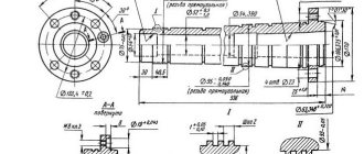
Drawing and design of the device
The design of the spindle depends on a large list of factors. For example, on what work will need to be completed, or on the speed at which the work will occur. You can also add types of machine to this list, since different types require different spindles.
Requirements for the spindle unit
In the past, the main support for this unit was the bearings on which the spindle rotates. The deviation on them reached about one micrometer. Now everything has changed: now the requirements for modern spindles have increased, and they are manufactured using either magnetic or air supports.
This allows you to achieve much better results than when using bearings: now deviations from the norm are only about two-tenths of a micrometer, which allows you to work with even the most complex parts without fear of producing defects.
However, two tenths of a micrometer is not a limit. Using a flywheel that accelerates the spindle, it is possible to reduce the error to three hundredths of a micrometer, which is much less than the previous result. True, such work must be performed after the flywheel is turned off. That is, work is performed due to inertia, with the help of which the spindle continues to move.
Here is a list of requirements that spindle units must meet:
- Accuracy. This requirement is checked based on the machine for which the spindle is needed and the application.
- Processing speed . Spindle units always rotate at different speeds (this depends on the type). To put it bluntly: the faster, the better. The speed determines the level of quality of the completed part.
- Stiffness . It's not the same with speed. That is, the lower, the better. It is calculated using the ratio of the spindle deflection and the level of radial runout. Having calculated the resulting number for two spindles, we can say which one is better.
- "Lifetime" . This indicator means how long the spindle can last when performing the intended work. It depends on which bearing is used during operation. Naturally, the worse it is, the faster the spindle assembly will break.
- Vibration resistance . Naturally, during operation the machine vibrates a lot, which can lead to defects if the spindle does not meet this requirement. If the spindle assembly does not tolerate vibration well, then the level of accuracy during operation will be noticeably lower.
- Maximum heating level . This is one of the most important requirements. During operation, the spindle assembly gets very hot due to the friction force, and therefore sometimes it needs, so to speak, to “rest” from work. If it gets too hot, it may begin to change and break, so you need to choose the one that is most resistant to high temperatures.
- Maximum carrying weight . Thanks to this requirement, it is possible to determine what weight the tools can be mounted on the spindle assembly. The size of the tool used also depends on this indicator.
Taking into account all these requirements for the spindle, you can choose the spindle unit that is best and most suitable for the job.
Purpose and principle of operation
The most important and, as a result, the main purpose of the spindle assembly is to attach a chuck to it, which in turn is intended for clamping the workpiece of the future part.
Reference! The workpiece is secured to the spindle using a special chuck, faceplate or collet clamp, which are attached to the end of the spindle.
Main parameters of VMS
The main parameters: engine power and torque, rotation speeds, permissible cutting forces, were assigned based on an analysis of the processing modes of steel and aluminum workpieces with face, long-edge, end, disk cutters, as well as boring, drilling and thread-processing tools (drills, reamers, cutters and etc.). Hard alloy and ceramics were used as tool materials. When choosing processing modes, we took into account the fact that when accelerating the above-determined rotation speeds, a gap may arise in the conical connection of the mandrel and spindle, which must be eliminated. The main parameters of the VMS developed within the framework of the state contract are presented in the table.
Fig.5. VMS HSK 100 (longitudinal section)
In Fig. Figure 5 shows the design of a VMS with a HSK-A100 cone. The rotor 1 of the electric motor is installed with interference to transmit torque to the spindle 2. The influence of the electromagnetic fields of the motor is reduced by rings 3 made of non-magnetic material, which can also be used for balancing. Spindle 2, together with the electric motor rotor and other rotating parts, is balanced until a residual imbalance is achieved, at which the center of gravity of the spindle shifts by no more than 1...2 µm. The stator 4 with a cooling jacket 7 is installed in the VMS housing 5 and is cooled when liquid is supplied to the cavity 6 of this jacket. The same system is used to cool the bearings. The front support of the spindle is double angular contact ball bearings 8 and 9, the tension in which is provided by springs 10 (at high rotation speeds) and pneumatic cylinder 11 (at lower frequencies and higher loads). The tool is installed in a mandrel 12, which is secured using a clamping mechanism 13 on the spindle, based in a connection 14 of the HSK-A type. The release of the mandrel 12 is carried out by supplying oil under pressure into the right cavity 15 of the hydraulic cylinder 16, the movable body of which is connected to the spindle 2 through the clamp 17. Thus, when the mandrel 12 is released, the axial force of the spring release is perceived only partially by the spindle supports. The angular position of the spindle is monitored by a sensor, which consists of a magnetized disk 18 mounted on the spindle and a reading head 19 mounted on the housing flange. The vibration sensors 20 and the movement of the front end 22 are located in the VMS housing. Temperature sensors are located in close proximity to the outer rings of the supports and in Fig. 5 are not shown. The coolant supply is carried out through the nozzles 23 or through the hole in the rod 24 of the clamping mechanism 13.
User manual
Before using a spindle with a lathe chuck to work with workpieces at all, it is necessary to carry out a break-in, which will be discussed a little later.
After the running-in has been completed, you can begin the work itself. If bearings are used in the spindle assembly, they are lubricated with a special lubricant, which helps to use the spindle's full capabilities at high speed.
This allows the spindle assemblies to last for as long as the manufacturers allot them. The spindle is designed so that this putty can lubricate all moving parts without allowing it to escape from the bearing.
Also, thanks to the design, not only the lubricant cannot get out, but also various dirt cannot get inside the spindle assembly.
Washing must be done with careful adherence to measures to ensure the cleanliness of the workplace and tools. When washing the bearing, if extreme or excessive play is detected, as well as wear of the running tracks or chipping of the textolite separator, it is recommended to completely replace the spindle bearings.
In addition to the above, in a number of cases when the spindle has a high degree of technological load, and its operating mode is or is close to the “24-hour” category, the lubricant in the bearings should be replaced after an empirically determined period of spindle operation.
Making the front (back) headstock
For a homemade machine, you can make a headstock with your own hands. Suitable:
- wooden board;
- thick plywood (10 mm);
- a metal sheet of small thickness that can be cut with metal scissors.
It is easier to make a headstock if a drill is chosen as the basis for the lathe. You need to make a stand with your own hands, where the drill will be fixed rigidly and its axis will be strictly horizontal.
Both centers of the headstocks must be firmly attached; this is an important condition. The tailstock should be able to move along the axis of rotation and be firmly fixed in the right place
Read also: Do-it-yourself workbench for a miter saw
The type of electric drive and its power are selected with your own hands, depending on the future purpose of the lathe. But the engine power should not be less than 250 W, otherwise nothing sensible can be turned on the machine.
Detailed video about the design of the headstock:
How to adjust and repair a spindle
Running in or adjusting the spindle is carried out as follows: you need to perform five cycles each for twenty minutes. In this case, it is necessary to take breaks between cycles of approximately two minutes.
If the operating conditions were violated, and also if the air in the room where the work was carried out was heavily polluted with dust and dirt, then the rubbing surfaces quickly become unusable, the lubricant, which is poured during production and should serve throughout the entire period of work, begins to lose its properties.
Because of this friction, it begins to cause a strong increase in temperature and the bearings, after some time of such work, become unusable and can no longer perform their functions.
To avoid such a sad development of events, it is necessary to immediately stop working with the workpiece at the first signs of overheating, as well as when vibrations and unusual sounds appear in the spindle assembly and urgently carry out maintenance of the spindle. It consists of: removing protection from the spindle assembly, cleaning and lubricating with new, high-quality lubricant, which is designed for high speeds.
Important!
Do not forget about the choice of brand, as it depends on what type of spindle and bearing is used.
Headstock device
The main component of the front tank is the spindle. The spindle head is fixed to the left edge of the bed. This is the most important detail of the entire structure.
Various necessary fixtures, tools, and mandrels are fixed in the inner conical hole of the spindle.
How does it work
The movement of the spindle is transmitted from the V-belt pulley. All shafts and the spindle itself are mounted on rolling bearings.
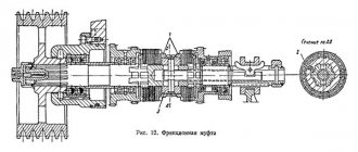
When the machine rotates in a forward direction, large torques are required. This occurs due to the large number of discs that are located on the left side of the friction clutch.
If the gearbox is fixed in the bed frame, then it is connected to the spindle by a belt drive. Such equipment models are called split-drive machines.