05.06.2020
The machine allows you to process parts for a wide variety of purposes. Modern universal models have many parameters, with the help of which work with products is carried out without difficulties. But this tool also has a vulnerable aspect - interaction with objects of inappropriate shape. A lathe chuck faceplate is an easy solution in situations like this.
Large products do not fit into the machine itself, so it is impossible to secure them in the required position. As for non-standard shapes, usually the clamping device, which acts as a fastening element, damages them. Squeezing is not very good for flat materials, the edges may crack or bend. It is especially unpleasant when various fittings are located in these places. And the object itself is quite capable of being damaged in such a situation. Accordingly, it is strictly not recommended to start processing without a specialized adapter.
Why do you need a faceplate on a lathe?
If there is a displacement along the spindle axis, as well as other obstacles to normal fastening through the chuck jaws, then installation of an adapter is mandatory. Fixation to the disk occurs through pressing against the equipment. If it is impossible to do this without damage, then there are variations of various fastenings that have strict specialization. Numerous offers on the market allow you to select fasteners for almost any model. However, no one bothers you to make calibrated fasteners for a specific task.
After installing the disk, it is imperative to make sure that the correct axial position is maintained. Indeed, unlike insertion directly into the cartridge, the indicated technique does not at all guarantee automatic centering. Therefore, you will have to do a little reconciliation.
It is noteworthy that the adapter faceplate can also help out in a situation where you have to interact not with the unusual shape of the part, but with a non-trivial cutting tool. That is, the blade device is already attached. But this is a fairly rare situation.
Requirements for faceplates
As has already been said several times above, before entering the market, faceplates must undergo certification , which certifies the buyer of their compliance with the standards established by the state. So, for example, faceplates should be:
- Made of cast iron (grade SE20, GOST 1412) or steel (35L, GOST 977);
- They are equipped with a classic circular scale , the division value of which should not exceed 1 o;
- Perfectly calibrated and centered. Checks must be carried out regularly using the methods described in regulatory documents.
A complete list of requirements for faceplates is listed in the regulatory document GOST 16935-93, group No. 27.
Design
It makes no difference which machine is used: metal or wood. This device for securing objects is suitable in both situations. The most common discs are made of steel and cast iron. Grooves and recesses are made on them. The main goal is reliable fixation of the object. Depending on which grooves are located on the surface, there is a certain list of shapes with which a given fastener is allowed to interact.
In addition, the equipment itself is often connected to the spindle using hubs. But the models that are mounted on the cartridge are easy to distinguish. The hubs do not look like cones, they are strict cylinders.
In many variations, the size of the faceplate allows you to install additional clamps on it. Usually clamp type. Then the future product is clamped according to the principle of a vice if it has protruding parts that ignore the mechanical compression pressure.
Do not forget that atypical processing is always a certain risk. The manufacturer did not intend such an action, which means there is a possibility of destruction of the product upon startup. And also the scattering of fragments over a large area. Accordingly, the main weapon in this case is a thorough balance check, calculation, and test run. Theoretically, a danger also arises for the equipment; it can be damaged if the fasteners are set inaccurately.
Attention and caution are the main rules that must be followed.
Main types of equipment
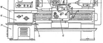
Most lathes are used to work with the external and internal surfaces of parts of various shapes, including conical, cylindrical and shaped.
Various types of machines also allow drilling holes and processing ends. Now let's talk about what types of devices are available today. The main classification of lathes is based on their purpose, the functions they perform and design features.
1. Screw-cutting lathes. They are universal and designed to perform a large number of operations. It is also important that they provide a high level of accuracy. This type of equipment is also required for thread cutting.
The first types of screw-cutting lathes appeared quite a long time ago. Over time, their design improved, they became more and more functional and perfect. The most modern models are equipped with CNC - numerical control. This function allows you to set basic operating parameters, after which the automation will monitor their compliance without human intervention.
When choosing a model of a screw-cutting lathe, it is important to take into account its main characteristics:
- Maximum spindle head rotation speed, as well as the ability to fine-tune it.
- The diameter of the rod installed in the hole.
- Torque.
- Rated power.
- Number of feeds of longitudinal and transverse type.
- Possibility of cutting various types of threads.
All these characteristics depend on the design of the screw-cutting lathe and its type. You should buy such equipment only from trusted sellers - official dealers of large companies.
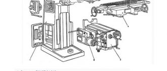
2. Vertical lathes. Devices from this group are designed to work with workpieces with large weight and diameter, but with low height. This category includes elements of turbines and generators, flywheels, gears, and so on. They are used for surface and end processing, grooving and milling, and can also perform grinding and threading.
Unlike other types of machines, in these devices the main movement is made by the faceplate, and the input is carried out by the supports. Most modern machines are equipped with a CNC function, which allows you to automate a significant part of the work.
3. Lathe machines. The main purpose of this type of lathe is to process parts that are bodies of rotation. However, they are best suited for working with workpieces of large diameter, but with limited thickness. This category includes, for example, wheels, gears, flanges, and so on. Lathes are designed for processing ends, threading, boring internal surfaces, and so on. The axis of rotation in these devices is located in the horizontal plane.
Lathes are practically not used in modern production. For the most part, they were replaced by rotary turning machines. Lathes today are more often used in workshops for the production of single products with large dimensions and repair work.
- Faceplate for a lathe in Moscow
4. Turret lathes. They are designed to work with parts made of calibrated rod. They are distinguished from universal lathes by the presence of a turret - a special holder for the tool. Because it can be calibrated during operation, many parts can be produced in one setup. In this case, there is no need to reconfigure the machine. Modern models of these machines allow you to install up to 12 tools in the head. As a result, they can be used to perform almost all types of processing:
- Boring.
- Countersinking.
- Drilling.
- Shaped turning.
- Thread cutting and so on.
5. Turning and milling machining centers. As the name suggests, they combine the functions of lathes and milling machines. The center includes a milling head, which makes these machines direct competitors to turning-turret machines in terms of the large number of operations performed:
- turning;
- milling;
- chiselling grooves;
- grinding;
- drilling holes;
- thread cutting.
Due to their advantages, machining centers can be considered one of the most promising developments. All main models are equipped with CNC, which allows you to automate most turning operations. The disadvantages of this type of equipment include the fairly high cost and serious requirements for the qualifications of specialists.
6. Automatic longitudinal turning machines. Their main task is the production of serial products from rods made of various grades of steel, aluminum, and copper. They allow you to perform various types of turning and milling work with a tolerance of no more than 0.1 mm. The machines can process round and hexagonal bars, as well as shaped profiles and wire. There are various types of these devices in which movable and stationary spindle heads are installed. The devices can be single-spindle or turret. The latter are distinguished by a wide range of functions and can carry out various operations without recalibration.
7. Multi-spindle lathes. These devices can also perform a full range of operations and are designed to work with workpieces formed from rods or pipes. They have high power and structural rigidity, and can perform various operations simultaneously. This type of machine is classified as expensive and is usually used by large enterprises to ensure mass production.
The listed types of devices are among the most common and are found in most enterprises. Of course, there are other types of lathes, but it is impossible to describe them in one article.
Before summing up, it is important to note another classification of equipment based on technological features.
1. Tabletop machines. They, as the name suggests, are fixed at the specialist’s workplace. Of course, this category includes devices that are small in size and weight. With their help, you can perform all main types of turning operations, including boring, milling and others. Of course, in terms of productivity, they are inferior to stationary options and are more often used by small companies than by large manufacturing firms. They are often used in everyday life due to their fairly modest energy consumption and affordable cost.
2. CNC machines. We have mentioned them several times in the article, but we would like to consider them separately. These machines have a higher cost and place higher demands on personnel qualifications. At the same time, almost all large enterprises are switching to them. The fact is that these models of lathes, regardless of their purpose and characteristics, are significantly more productive than their human-operated counterparts. They also provide a high level of accuracy.
- How to make a homemade metal lathe with your own hands
The following types of machines are available on the market today:
- Open. They use one stream of information. The device decodes it and then transmits commands to all component mechanisms.
- Closed. The principle of operation is the same as in open ones, but the information comes from two streams: from the reading mechanism and from the measuring device.
- Self-adjusting. The most advanced models that are capable of automatically adjusting their operation taking into account the data received from the measuring device.
Another classification of CNC machines is based on how control over work processes is ensured. In this case, the following are distinguished:
- Positioning machines. In them, the position of the processing mechanism is set before starting work.
- Rectangular machines. They are designed for processing step-shaped workpieces. Such devices can independently switch gears from longitudinal to transverse and back.
- Contour machines. They provide complete control over the execution of operations using built-in automation.
3. Machines with continuously variable drive. Their main difference from other models is the ability to control and change the spindle speed. Such machines are designed for processing the external and internal surfaces of workpieces. Other advantages of this type of equipment include its reliability and simple operation due to the absence of a gearbox. In various machine models, rotation control is carried out using a mechanical, electrical or hydraulic drive.
4. Pipe cutting machines. These machines belong to the highly specialized category, as they allow you to perform a fairly limited set of actions: end processing, thread cutting and actual cutting. Typically, these machines are also equipped with CNC, which allows them to carry out most operations automatically.
Types and purpose of faceplates
Many people mistakenly believe that this item is becoming a universal way to solve any problem of processing atypical parts. But to check, this adapter is very strictly specialized. In other words, to work with a certain category of forms you need your own row of disks.
Of course, one option is quite capable of working with a whole range of parts of similar dimensions at once. But the specifics still remain very clear. Accordingly, there are a number of different adapters that differ in:
- Purpose.
- Structural parameters.
- Fastening the faceplate.
- Even production materials.
Therefore, you should always have a whole set on hand, which implies different purposes. Moreover, some of them are homemade. And not only because saving is a great solution. There are also more prosaic reasons. Some unexpected variations may simply not be available on the market or in the assortment of the nearest supplier. We will talk about making such a tool below. Now let's move directly to species diversity.
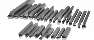
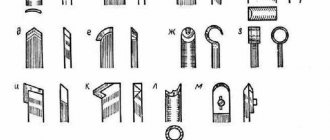
T-slot disc
The structure has a surface on which the recesses are located. And the fastening is ultimately done using screws. This is perhaps one of the most universal types. There are a huge number of types of products that can be easily installed on such equipment.
The quantitative factor of the grooves also changes. The more there are, the greater the broad purpose implied. Even at the manufacturing stage, the disk parameters are easily adapted to the current situation. Thus, this method is most often used.
This is a good option as a faceplate for a milling machine. However, as already indicated, a wide variety of uses are allowed.
With through grooves
The universal choice for metal processing. Suitable for wood, but there are fewer advantages. The main difference is the presence of through grooves. Their magnitude and frequency are determined by the task. Typically, all holes are located around a circle, at a certain radius. And sometimes you come across models where the groove is solid, representing a continuous semicircle.
Installation is done using screws. Often the part itself is placed directly on the disk with its reverse side. If for this purpose there are corresponding holes already in the product itself, of course.
In most cases, other mechanisms are installed on the surface of the adapter. They allow you to diversify the range of clamps with which the disc can interact and increase the adhesive capabilities.
With holes
The entire line of species in this category has one thing in common - a recess in the center. After all, with its help the disk itself “sits” on the cartridge. Accordingly, thread is used. But the remaining holes are located under already defined regulations. Whichever product line is intended to work, there will be so many grooves. Round, oval, and elongated options are used.
There are differences in how the workpiece is secured to the faceplate. Objects can be fixed not only with screws, but also with clamps, which greatly expands the variability.
Leashes
When it is intended to place a part between centers, the transmission of torque from the shaft to the product is ensured by just this type of disk. They are equipped with a special recess along their entire circumference, which is designed to hold the clamp. It encircles the future product, becoming something like a muff.
In addition, for fixation, there are different holes on the disk, usually in a T-shaped format. Their exact number varies within a free range. In fact, the drive faceplate does not have strict parameters in this regard; it all depends on the purpose.
With a square
The additional adapter is often shaped like an angle. It is attached to the disk part, leaving an empty flat surface on the other side. The workpiece is located on it. The meaning of this additional element is to reduce the mechanical factor for the object. Accordingly, it should be used if the product is vulnerable, has soft parts, or thin areas.
To ensure maximum stability, it is important to install fixation not only at one point on the surface, but to select at least three. More is acceptable, it all depends on the characteristics of the material used. It is also logical to use additional fasteners. For example, if the shape is thin and elongated, then a special adapter is suitable. The purpose of the faceplate trident chuck is to work with long wooden structures with a flat base.
Universal and special
Considering the fact that there are already many described variations of different models, manufacturers often try to minimize their diversity. Therefore, they create sets of universal adapters. Their essence is to minimize the wasted material. That is, one basic disk is produced, which, with the help of a device, becomes any of those described above. Fixing elements and teeth are installed on it.
It turns out something in the style of a screwdriver with a base and a dozen attachments. If you need a flat one, it’s easy; if you need a cross one, it’s even easier.
And special ones are washers made for a specific batch according to a special drawing, which will be useless in another production.
Simple tabletop mini machine
Adapter for installing a clamping chuck on an angle grinder
The second homemade mini-design is almost entirely made of wood, so the following is used in production:
- screwdriver;
- hacksaw;
- sandpaper;
- jigsaw;
- pliers.
- board No. 5 is better than oak;
- two dies for parquet;
- screws No. 45, about 10 pieces;
- construction dowel;
- aluminum plate;
- electric motor (can be from an old VCR);
- shaft from an old cassette player;
- thick bicycle spoke or pin;
- bolt and nut.
Assembling a lathe with your own hands.
- We saw off a piece of board 30 x 15 cm to create a base.
- We cut out two sections lengthwise from the parquet blocks: one with an outer groove, the second with an inner one. We drill one hole for self-tapping screws 5 cm from the ends. The length of the die will be equal to the future workpiece.
- We screw the parquet slats to the base with the grooves inward, and we get guides. There should be a whole parquet floor between them.
- We will make the tailstock from parquet, about 10 cm high, choosing a notch in the middle. In the lower part we cut out a wide hole into which we glue the nut. Subsequently, a bolt will be screwed into the nut to secure the rear strut.
- We attach a block to the tailstock, onto which we fix the dowel using a metal plate.
- The support for the cutter will be made from a knitting needle bent into the shape of a long bracket located along the bed. We fasten it with a couple of screws.
- The headstock is a block of wood onto which an electric motor is screwed using a metal bracket. When fastening, use thin rubber gaskets that reduce vibration. Before final fixation, you need to align the front and rear centers.
- You can make a faceplate with your own hands from a plastic washer, which we glue onto the shaft with hot-melt adhesive. We fuse several sharpened pins into the faceplate to secure the workpiece.
Thus, making a simple lathe with your own hands will not be difficult. Video about a homemade machine with a 125 W washing machine motor:
Operating rules
Let's briefly go through the main nuances of how to install and work with such an element, depending on the equipment.
On universal
In principle, what is a faceplate for a metal lathe chuck? It is an adapter with a special type of clamps. But at the same time, he himself is placed on the base according to different laws.
- An uneven surface, asymmetrical, always implies mounting on a clamp.
- To straighten the axle, you need to use lifting bars.
- Use a counterweight (usually included) to avoid vibration.
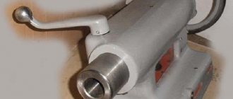
On rotary turning machines
There are fundamental differences here. If we constantly mentioned above that the washer is simply an additional adapter designed to simplify work with unusual workpieces, in this case it is the main element of the fastener. After all, the machine itself is a round table, on top of which a disk with several bushings is placed. Objects are mounted on them. What’s interesting is that even if the bushings themselves break or become unusable, they are replaced separately. And it becomes a kind of working surface that cannot be changed.
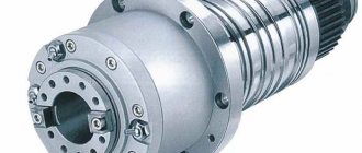
Self-centering washers
This is one of the most common types of nozzles. The main differences are that there is a large hole in the center of the surface. It is the same size as the bushings around the perimeter. The main task is to seal the contact with the shaft in order to increase the level of reliability and service life of the equipment.
The faceplate is self-sealing.
If you want to learn more about domestic motorcycles, we recommend watching videos about the IZH motorcycle and its model range.
We advise you to watch our video section, and you will immediately find the information you are interested in about the unique IZH motorcycle.
In general, the turner turned the washer and asked to mark exactly how to cut and drill =).
I decided that I would give him half of the crankcase and it would be better to measure everything myself =)
I like I like 6
Other entries in this logbook
Motor from Jupiter 4
I bought a seat, a carrot and a chrome wing assembly for RUR 500. A spacer is already welded into the seat. But I will still do my best to protect her! I'll paint it black. Read more
The project is moving towards its logical conclusion. I decided to abandon the backlight in the speedometer. I'll install turn signals for beauty's sake. Left. Read more
Comments
Only authorized users can leave comments
Russia, Moscow Region, Pushkino
I made the holes myself. And yes, there is no step on this faceplate - it rests on the crankcase, if you give it away with the crankcase, the turner will modify it. These holes are a pain in the ass.
- Answer
- March 1, 2021 at 2:23 pm
How to make a faceplate for a lathe chuck
When the assortment of stores does not suit the buyer, as well as in cases where the budget or time frame does not allow the purchase, homemade options are used. Of course, in order to produce such a product with your own hands, you must have the appropriate experience.
It is worth clarifying that we will be talking about a simplified design that is suitable only for basic parts. More complex options are not only problematic in production, but also have a very high cost, which means the event becomes expensive.
Creating a blank
- Initially, the necessary markings are applied to the timber. Using a compass, we mark the diameter, but it is better to take it with a margin of 2-3 mm, so that during further work, when you have to glue the parts, the size will not be smaller.
- Apply glue to the prepared elements. Press tightly and leave for 20 minutes.
- The next step is to create a metal washer. It is best to choose a size large enough for the nut so that it fits snugly and does not fall through. Sequentially weld it first from above, then from below.
- We install it on the spindle, and also select the grooves and holes. It is important to correctly determine the final task. Otherwise, it will not be possible to properly fasten the part. Please note that to install various devices such as a lathe vice, you must leave some space on the common surface. This means that you need to choose the appropriate plane size in advance.
- The last stage is the application of protective layers. Here the choice is obvious in favor of paint. It will not allow rust to appear on the outside. In addition, if you notice any unevenness during processing, it is quite possible to simply cut them down.
We tried to explain as fully as possible what a washer plan is, what it is needed for, and how its various variations are used. Most types can be purchased in the most convenient sets. It is not necessary to immediately take a large batch if there is no need for it. Kits that contain only one main drive and additional components for it are widespread.
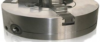
GOST 2675—80 Self-centering spiral-rack three-jaw chucks
GOST 2675—80 Self-centering spiral three-jaw chucks
GOST 2675—80 Self-centering spiral three-jaw chucks
The standard applies to self-centering spiral rack three-jaw lathe chucks mounted on machine spindles through adapter flanges and directly on the flanged ends of the spindles.
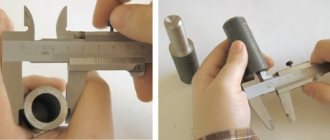
In total, the standard provides for ten standard sizes of lathe chucks : 80, 100, 125, 160, 200, 250, 315, 400, 500, 630 mm.
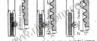
Depending on the method of installation on spindles, lathe chucks should be made of the following 3 types:
- Type 1 - with a cylindrical, belt and with fastening through an intermediate flange in accordance with GOST 3889;
- Type 2 - with mounting on the flanged ends of spindles under a rotary washer in accordance with GOST 12593;
- Type 3 - with mounting on the flanged ends of spindles in accordance with GOST 12595.
- Ten standard sizes -: 80, 100, 125, 160, 200, 250, 315, 400, 500, 630 mm;
- Version 1 - with solid cams;
- Version 2 - with assembled jaws;
- Accuracy class - N - normal; P – increased; B – high; A – especially high;
Self-centering three-jaw chuck. Type 1 - with cylindrical, belt and with fastening through an intermediate flange according to GOST 3889
GOST 2675-80 Self-centering three-jaw chuck. Type 1 - with a cylindrical belt
Self-centering three-jaw chuck. Type 3 - installation on the spindle cone, secured with screws through the chuck body into the end of the spindle flange according to GOST 12595
GOST 2675-80 Self-centering three-jaw chuck. Type 3 - installation on the spindle taper
Wood and metal processing
Installation on a faceplate. A workpiece of complex shape is fixed directly on the faceplate (body) of a four-jaw chuck or on a special faceplate - a cast iron disk with T-shaped radial grooves. If the end of the faceplate “beats” after installation on the spindle, then to ensure the perpendicularity of the end of the faceplate to the spindle axis, thin chips are removed from the end. The workpiece is attached to the faceplate in the following ways: - directly with bolts through the through grooves of the faceplate (if there are holes in the workpiece); - clamps with an L-shaped head (“crutches”). Crutches are made by forging (bent from rod material or welded crutches are not allowed). The workpiece is clamped by tightening the nuts on the back side of the faceplate; - clamp strips. One end of the clamping bar b rests on the head of a specially screwed bolt (or on a screwed support), and the second end presses the workpiece when the nut is screwed onto the screw. The clamping bar works according to the law of the lever, the clamping force is determined by the formula (N): - i.e., the closer the clamping screw is located to the workpiece, the greater the clamping force; - slats through the workpiece. With the appropriate shape, the workpiece is secured to the faceplate with strips, which are pressed with two screws.
A combination of different fastening methods is possible: cams and clamps, cams and slats through the workpiece, clamps and slats, etc.
The workpiece is first secured by preliminary tightening of the nuts “crosswise”, and then by final tightening. Over-tightening of nuts is not allowed. After securing and processing the first workpiece, stops are installed on the faceplate, which come into contact at several points with the surface of the workpiece. Using these stops, the position of subsequent blanks in the batch is recorded, which reduces the time of alignment and fastening.
An important condition for processing a workpiece on a faceplate is its balancing with a counterweight, which is assembled from cast iron washers of the same diameter, but different in mass, and is secured with a bolt in the groove of the faceplate against the unbalanced mass of the workpiece. The selection of the counterweight mass is checked by balancing directly on the machine. Balancing is done as follows. After securing the workpiece and the counterweight, the spindle is disconnected from the gearbox mechanism, and the spindle is allowed to rotate freely. Then they sharply turn the faceplate manually and monitor in what position and how quickly the faceplate stops. If the faceplate stops with the workpiece facing down, then add a counterweight, and if the counterweight is in the lower position, then reduce the load. Balancing has been achieved if, after turning the faceplate, it does not stop instantly, and the stop occurs in any position, regardless of the location of the workpiece and the counterweight.
Work on the faceplate is carried out with caution so that the hand does not get into the workpiece fastening area. In addition, periodically check whether the faceplate, workpiece and counterweight are securely fastened. Installation on a square. Blanks for bearing housings, brackets, pipes and similar parts are processed fixed to a square (Fig. 256). Squares can be cast or welded, their working planes are mutually perpendicular. The square is fastened with bolts to the faceplate, and the workpiece is secured to the square (with bolts through holes in the workpiece, with crutches or clamps). The square and the workpiece are balanced with a counterweight as described above. The position of the workpiece is checked using a thickness gauge.
In Fig. 257 shows an adjustable square. The position of the workpiece relative to the spindle axis can be adjusted using horizontal and vertical screws. Installation in fixtures based on the US P kit. At machine-building enterprises of small-scale and individual production, machine fixtures are assembled from parts of a standard kit. These are the so-called universal prefabricated devices (USP). The set consists of plates, faceplates, squares, stops, strips, clamps, screws, nuts and other parts manufactured with high precision. The necessary devices are quickly created from these parts. After processing a batch of workpieces, the device is disassembled and another device is assembled from the freed parts. USP is collected in special areas.
On the basis of the USP kit, various turning devices are assembled for fastening workpieces of complex shapes. In Fig. Figure 2 shows a device assembled on a faceplate from a standard round plate, a square, a rotary plate, and two clamps. This device can be used to process the workpiece on both sides.
Additional accessories
When turning thin-walled products or working with fragile wood, metal fastening rings are used. Having the skill of handling metal, you can make them yourself. Also paired with type C cams, screw inserts can be used that screw into a hole pre-drilled in the part. Chucks designed to solve specific woodworking problems:
- cam with independent adjustment - for eccentric turning;
- collet - clamps round workpieces when tightening the petals of a conical collet with a coupling nut. Has a small capture range;
- cylindrical - a tube with three or more threaded fasteners around its circumference; vice - for gripping rectangular workpieces. The parallel jaws are compressed by a screw;
- vacuum – for finishing. It works due to the difference in air pressure created by the pump;
- drilling – for fixing drills. Attached to the tailstock quill.