Here you will learn:
- Why are heating system pump calculations necessary?
- Selection of a pump according to its main characteristics
- How to calculate a heating circulation pump based on boiler power
- How to choose a circulation pump based on the data received
- Table for empirical pump selection
- Cavitation in the heating system and water supply system
- Recommendations for installing pumps
The main task of the circulation pump is to improve the circulation of coolant through the elements of the heating system. The problem of already cooled water entering heating radiators is well known to residents of the upper floors of apartment buildings. Such situations are associated with the fact that the coolant in such systems moves very slowly and has time to cool before it reaches parts of the heating circuit located at a considerable distance.
When operating autonomous heating systems in country houses, in which water circulates naturally, you may also encounter a problem when radiators installed at the farthest points of the circuit barely heat up. This is also a consequence of insufficient coolant pressure and its slow movement through the pipeline. The installation of circulation pumping equipment allows you to avoid such situations both in apartment buildings and in private houses. By forcibly creating the required pressure in the pipeline, such pumps provide high speed movement of heated water even to the most distant elements of the heating system.
The pump increases the efficiency of existing heating and allows you to improve the system by adding additional radiators or automation elements
Heating systems with natural circulation of liquid that transfers thermal energy are effective when they are used to heat small houses. However, if you equip such systems with a circulation pump, you can not only increase the efficiency of their use, but also save on heating by reducing the amount of energy consumed by the boiler.
In terms of its design, the circulation pump is a motor whose shaft transmits rotation to the rotor. A wheel with blades is installed on the rotor - an impeller. Rotating inside the working chamber of the pump, the impeller pushes the heated liquid entering it into the discharge line, forming a coolant flow with the required pressure. Modern models of circulation pumps can operate in several modes, creating different pressures of the coolant moving through them in heating systems. This option allows you to quickly warm up the house when cold weather sets in by running the pump at maximum power, and then, when a comfortable air temperature has formed throughout the building, switch the device to an economical operating mode.
Circulation pump device for heating
All circulation pumps used to equip heating systems are divided into two large categories: devices with a “wet” and “dry” rotor. In pumps of the first type, all rotor elements are constantly in the coolant environment, and in devices with a “dry” rotor, only a part of such elements are in contact with the pumped medium. Pumps with a “dry” rotor are distinguished by greater power and higher efficiency, but they make a lot of noise during operation, which cannot be said about devices with a “wet” rotor, which produce a minimal amount of noise.
Why do you need a circulation pump?
It is no secret that most consumers of heating services living on the upper floors of high-rise buildings are familiar with the problem of cold radiators. Its cause is the lack of necessary pressure. Because if there is no circulation pump, the coolant moves through the pipeline slowly and, as a result, cools down on the lower floors. That is why it is important to correctly calculate the circulation pump for heating systems.
Owners of private households often face a similar situation - in the most remote part of the heating structure, the radiators are much colder than at the starting point.
Experts consider the optimal solution in this case to be the installation of a circulation pump, as it looks like in the photo. The fact is that in small houses, heating systems with natural circulation of coolants are quite effective, but even here it would not hurt to think about purchasing a pump, since if you properly configure the operation of this device, heating costs will be reduced. What is a circulation pump? This is a device consisting of a motor with a rotor immersed in a coolant. The principle of its operation is as follows: by rotating, the rotor forces a liquid heated to a certain temperature to move through the heating system at a given speed, resulting in the creation of the required pressure.
Pumps can operate in different modes. If you set the circulation pump in the heating system to maximum operation, a house that has cooled down in the absence of the owners can be warmed up very quickly. Then consumers, having restored the settings, receive the required amount of heat at minimal cost.
Circulating devices come with a “dry” or “wet” rotor. In the first version, it is partially immersed in the liquid, and in the second - completely. They differ from each other in that pumps equipped with a “wet” rotor make less noise during operation (about
Calculation of a heat pump using a bivalent scheme.
A bivalent scheme is when an additional heat source is added to the heat pump. What does it mean? Let's assume that we calculated the heat loss and it turned out to be 10 kW. We can install a heat pump of such power, make an external geothermal circuit for it and provide ourselves with the necessary heat for the entire heating season. Thermopoies are calculated for a cold five-day period. Let's take the city of Krasnodar as an example. The cold five-day period is -19C. Such temperatures rarely occur in this city and do not last long. The main heating season is around zero degrees. Sometimes the temperature drops to -8 - -10C. Such days are no more than 20%. In this case, heat loss is calculated at -10C, and the missing power is obtained from another source. Such a source can be a diesel, electric, solid fuel or gas boiler. The bivalent scheme allows you to install a heat pump of lower power and significantly save on the cost of the pump itself and the cost of work on arranging the external circuit.
The bivalent circuit can also be useful in cases where there is not enough electrical power. Then the heat pump is calculated based on the allocated electrical power. Let's say the heat output was 20 kW. The consumption of the heat pump at this power will be 5 kW, and the allocated electrical power for the house will be 7.5 kW. The remaining 2.5 kW is unlikely to be enough for a modern home. In this case, the heat pump is taken at 12 kW, it can cover 80 percent of the heating season, and the missing 8 kW can be covered by a small diesel or liquefied gas boiler.
In all cases, the calculation of a heat pump is made based on a specific object and specific technical specifications.
If you need to make a heat pump calculation, you can contact. Our specialists will be able to provide comprehensive information on all points of calculations. Social Like
Procedure for calculating pump parameters
The circulation pump must solve two main problems:
- create in the heating system such a coolant pressure that will be able to overcome the hydraulic resistance that arises in individual structural elements;
- provide the required performance and thereby facilitate the movement of heat through the system, sufficient to heat the house.
Based on the assigned tasks, calculation of the circulation pump for heating is required to determine the thermal energy needs of the house and the hydraulic resistance of the entire system. Without knowing these parameters, it is impossible to select a device for forced movement of coolant.
Functions, types and principles of operation of circulation pumps
What is a circulation pump (pump) needed for? According to the operating principle of forced circulation systems, the movement of heated liquid occurs due to excess pressure created by pumping equipment.
Accordingly, the pump is tasked with solving two problems:
- Ensuring high speed of coolant movement;
- Creation of excess pressure sufficient to overcome the hydraulic resistance that occurs in the system elements.
The first is the main one in terms of heating efficiency and economy. Indeed, at a high speed of movement of the coolant, the difference in its temperatures in the supply and return pipelines decreases - the liquid simply does not have time to cool. As a result:
- Even with a significant length of lines, uniform heat distribution in the serviced rooms is ensured;
- Heating the liquid requires less energy consumption (compared to gravitational systems, savings can be up to 20-30% );
- Heat sources (boilers, other types of heaters) operate in a gentle mode ;
- It becomes possible to create closed (sealed) systems in which a coolant with high heat capacity can be used (for example, antifreeze, a mixture or aqueous solution of glycols, etc.).
Choosing a heat pump for heating a house: a review of heating systems of the future.
Options and technology for installing a one-pipe heating system with your own hands. Read here.
How to make a two-pipe heating system for a private house with your own hands:
https://klimatlab.com/otoplenie/sistema/dvuhtrubnaya-chastnogo-doma-svoimi-rukami.html
For the owner of such a system, its design, installation and operation are much cheaper.
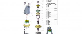
The design of a circulation pump for heating includes several main components and parts:
- Impeller (impeller) for pumping liquid;
- Electric motor for driving the impeller;
- A pumping chamber with inlet and outlet (supply and pressure) pipes that are connected to the pipelines;
- Housings;
- Terminal box for electrical connections and installation of control elements (in case of modification of the device with variable speed control).
How it works:
- The coolant enters the pumping chamber through the inlet pipe .
- Here it is captured by an impeller driven by an electric motor.
- At increased pressure , it is sent to the outlet pipe , which is connected (like the inlet) to the heating system line.
Manufacturers offer many different designs of pumping equipment. Most of them can be classified into one of two classes:
- Devices with a “wet” rotor;
- Pumps with a “dry” rotor.
In the first, the impeller, as a rule, is made in a single unit with the electric motor rotor. As a result, the rotor is immersed in the pumped liquid.
The main feature of the second type of design is the rotor, isolated from the impeller and coolant due to the mechanical seal.
In the version with a “wet” rotor, the liquid simultaneously performs the functions of lubrication and heat removal.
Each solution has its own advantages and disadvantages. In the version with a “wet” rotor, the liquid simultaneously performs the functions of lubrication and heat removal . This made it possible to obtain compact designs with minimal operating noise. It is these pumps that are widely used for domestic applications - hot water supply and autonomous heating.
The version with a “dry” rotor is characterized by higher efficiency values and maximum power , which determined the use of such equipment in systems requiring high performance, for example, mini-boiler houses that supply heat to apartment buildings.
Calculation of pump performance
The performance of this device is usually denoted in formulas by the letter Q. This value reflects the amount of heat transferred per unit of time.
For calculation use the formula:
Q=0.86R:TF-TR, where
R is the thermal power required to heat the room (kW); TF is the temperature of the coolant in the supply pipe of the system (°C); TR is the temperature in the pipeline at the outlet of the system (°C).
In European countries, the R indicator depends on operating conditions; it is usually calculated in accordance with the standards:
- in houses with no more than two apartments, the power of the circulation pump for heating is taken equal to 100 W/m²;
- in multi-apartment buildings - 70 W/m².
When pump calculations are performed for buildings with poor thermal insulation, the value of the above indicators must be increased. If the building is well insulated, the R value is used, which ranges from 30 to 50 W/m².
How to calculate and choose a heat pump
Calculation and design of heat pumps
How to calculate and select a heat pump.
As you know, heat pumps use free, renewable energy sources: low-grade heat from air, soil, underground, open, non-freezing reservoirs, waste and waste water and air, as well as waste heat from technological enterprises. In order to collect this, electricity is expended, but the ratio of the amount of thermal energy received to the amount of electrical energy consumed is about 3–7 times.
If we talk only about the sources of low-grade heat around us for use for heating purposes, this is; outside air with a temperature from –3 to +15 °C, air exhausted from the room (15–25 °C), subsoil (4–10 °C) and groundwater (about 10 °C), lake and river water (5–10 °C), surface soil (below the freezing point) (3–9 °C) and deep soil (more than 6 m - 8 °C).
Heat extraction from the environment (inner district).
A liquid working medium, refrigerant, is pumped into the evaporator at low pressure. The thermal level of temperatures surrounding the evaporator is higher than the corresponding boiling point of the working medium (the refrigerant is selected such that it can boil even at sub-zero temperatures). Due to this temperature difference, heat is transferred to the environment, the working environment, which at these temperatures boils and evaporates (turns into steam). The heat required for this is taken from any of the above low-potential heat sources.
Learn more about renewable energy sources
If atmospheric or ventilation air is chosen as a heat source, heat pumps operating according to the air-water scheme are used. The pump can be located indoors or outdoors, with a built-in or remote condenser. Air is blown through the heat exchanger (evaporator) using a fan.
Groundwater with a relatively low temperature or soil from the surface layers of the earth can be used as a source of low-potential thermal energy. The heat content of the soil mass is generally higher. The thermal regime of the soil in the surface layers of the earth is formed under the influence of two main factors - solar radiation incident on the surface and the flow of radiogenic heat from the bowels of the earth. Seasonal and daily changes in the intensity of solar radiation and outside air temperature cause fluctuations in the temperature of the upper layers of the soil. The penetration depth of daily fluctuations in outside air temperature and the intensity of incident solar radiation, depending on specific soil and climatic conditions, ranges from several tens of centimeters to one and a half meters. The depth of penetration of seasonal fluctuations in outside air temperature and the intensity of incident solar radiation does not, as a rule, exceed 15–20 m.
Types of horizontal heat exchangers:
— heat exchanger made of series-connected pipes; — heat exchanger made of parallel connected pipes; — horizontal collector laid in a trench; — heat exchanger in the form of a loop; — a heat exchanger in the shape of a spiral located horizontally (the so-called “slinky” collector); — a heat exchanger in the shape of a spiral located vertically.
Water accumulates solar heat well. Even in the cold winter period, groundwater has a constant temperature of +7 to +12°C. This is the advantage of this heat source. Due to the constant temperature level, this heat source has a high conversion rate through the heat pump throughout the year. Unfortunately, groundwater is not available in sufficient quantities everywhere. When using groundwater as a source, supply is carried out from a well using a submersible pump to the entrance to the heat exchanger (evaporator) of a heat pump operating according to the “water-water/open system” scheme; from the output of the heat exchanger, water is either pumped into another well, or dumped into a reservoir. The advantage of open systems is the ability to obtain large amounts of thermal energy at relatively low costs. However, wells require maintenance. In addition, the use of such systems is not possible in all areas. The main requirements for soil and groundwater are as follows:
— sufficient permeability of the soil, allowing water reserves to be replenished; - good chemical composition of groundwater (for example, low iron content), which avoids problems associated with the formation of deposits on pipe walls and corrosion.
Open systems are more often used to supply heating or cooling to large buildings. The world's largest geothermal heat transfer system uses groundwater as a source of low-grade thermal energy. This system is located in the USA in Louisville, Kentucky. The system is used for heat and cold supply of a hotel and office complex; its power is approximately 10 MW.
Let’s take another source - a reservoir; loops of plastic pipe can be laid on its bottom, a “water-water/closed system” scheme. An ethylene glycol solution (antifreeze) circulates through the pipeline, which transfers heat to the refrigerant through the heat exchanger (evaporator) of the heat pump.
The soil has the ability to accumulate solar energy over a long period of time, which ensures a relatively uniform temperature of the heat source throughout the year and, thus, a high conversion coefficient of the heat pump. The temperature in the upper layers of the soil varies depending on the season. Below the freezing line, these temperature fluctuations are significantly reduced. The heat accumulated in the ground is extracted through horizontally laid sealed heat exchangers, also called ground collectors, or through vertically laid heat exchangers, so-called geothermal probes. The ambient heat is transferred by a mixture of water and ethylene glycol (brine or medium), the freezing point of which should be approximately -13°C (take into account the manufacturer's data). Thanks to this, the brine does not freeze during operation.
This means that there are two possible options for obtaining low-grade heat from the ground. Horizontal laying of plastic pipes in trenches with a depth of 1.3–1.7 m, depending on the climatic conditions of the area, or vertical wells with a depth of 20–100 m. Laying of pipes in trenches can also be done in the form of spirals, but with a laying depth of 2– 4 m, this will significantly reduce the total length of the trenches. The maximum heat transfer of surface soil is from 7 to 25 W per m.p., from geothermal 20-50 W per m.p. According to manufacturing companies, the service life of trenches and wells is more than 100 years.
A little more about vertical ground heat exchangers.
Since 1986, research has been carried out on a system with vertical ground heat exchangers in Switzerland, near Zurich [4]. A vertical coaxial type ground heat exchanger with a depth of 105 m was installed in the soil mass. This heat exchanger was used as a source of low-grade thermal energy for a heat transfer system installed in a single-apartment residential building. The vertical ground heat exchanger provided a peak power of approximately 70 W per meter of length, creating a significant thermal load on the surrounding ground mass. The annual production of thermal energy is about 13 MWh.
At a distance of 0.5 and 1 m from the main well, two additional wells were drilled, in which temperature sensors were installed at a depth of 1, 2, 5, 10, 20, 35, 50, 65, 85 and 105 m, after which the wells were filled clay-cement mixture. Temperatures were measured every thirty minutes. In addition to the ground temperature, other parameters were recorded: the speed of movement of the coolant, energy consumption by the compressor drive, air temperature, etc.
The first observation period lasted from 1986 to 1991. Measurements have shown that the influence of the heat of the outside air and solar radiation is observed in the surface layer of soil at a depth of up to 15 m. Below this level, the thermal regime of the soil is formed mainly due to the heat of the earth's interior. During the first 2-3 years of operation, the temperature of the soil mass surrounding the vertical heat exchanger dropped sharply, but every year the temperature drop decreased, and after a few years the system reached a regime close to constant, when the temperature of the soil mass around the heat exchanger became 1 lower than the initial one. -2 °C.
In the fall of 1996, ten years after the system began operating, measurements were resumed. These measurements showed that the ground temperature did not change significantly. In subsequent years, slight fluctuations in ground temperature within 0.5 °C were recorded depending on the annual heating load. Thus, the system reached a quasi-stationary mode after the first few years of operation.
Based on experimental data, mathematical models of the processes occurring in the soil mass were constructed, which made it possible to make a long-term forecast of changes in the temperature of the soil mass.
Mathematical modeling showed that the annual decrease in temperature will gradually decrease, and the volume of the soil mass around the heat exchanger, subject to a decrease in temperature, will increase every year. At the end of the operating period, the regeneration process begins: the soil temperature begins to rise. The nature of the regeneration process is similar to the nature of the process of “selection” of heat: in the first years of operation there is a sharp increase in soil temperature, and in subsequent years the rate of temperature increase decreases. The duration of the “regeneration” period depends on the duration of the operating period. These two periods are approximately the same. In the case under consideration, the period of operation of the ground heat exchanger was thirty years, and the “regeneration” period is also estimated at thirty years
Thus, heating and cooling systems for buildings using low-grade heat from the earth represent a reliable source of energy that can be used everywhere. This source can be used for quite a long time and can be renewed at the end of the operating period.
Calculation of a horizontal heat pump collector
The heat removal from each meter of pipe depends on many parameters: laying depth, presence of groundwater, soil quality, etc. Approximately we can assume that for horizontal collectors it is 20 W.m.p. More precisely: dry sand - 10, dry clay - 20, wet clay - 25, clay with a high water content - 35 W.m.p. The difference in coolant temperature in the forward and return lines of the loop in calculations is usually taken to be 3 °C. On the collector site, no buildings should be erected so that the heat of the earth, i.e. our energy source was replenished with energy from solar radiation.
The minimum distance between laid pipes must be at least 0.7–0.8 m. The length of one trench can vary from 30 to 150 m, it is important that the lengths of the connected circuits are approximately the same. It is recommended to use an ethylene glycol solution (medium) with a freezing point of approximately -13 °C as the primary coolant. In the calculations, it should be taken into account that the heat capacity of the solution at a temperature of 0°C is 3.7 kJ/(kg K), and the density is 1.05 g/cm3. When using a medium, the pressure loss in the pipes is 1.5 times greater than when circulating water. To calculate the parameters of the primary circuit of a heat pump installation, you will need to determine the flow rate of the medium:
Vs = Qo 3600 / (1.05 3.7 .t),
where .t is the temperature difference between the supply and return lines, which is often taken equal to 3 oK. Then Qo is the thermal power received from a low-potential source (ground). The latter value is calculated as the difference between the total power of the heat pump Qwp and the electrical power spent on heating the refrigerant P :
Qo = Qwp – P, kW.
The total length of the collector pipes L A for it are calculated using the formulas:
L = Qo/q,
A = Lda.
Here q is the specific (from 1 m of pipe) heat removal; da – distance between pipes (laying pitch).
Calculation example. Heat Pump.
Initial conditions: heat demand of a cottage with an area of 120–240 m2 (based on heat losses taking into account infiltration) – 13 kW; The water temperature in the heating system is taken to be 35 °C (underfloor heating); The minimum coolant temperature at the outlet to the evaporator is 0 °C. To heat the building, a heat pump with a capacity of 14.5 kW was selected from the existing technical range of equipment, taking into account the losses due to the viscosity of the medium, when selecting and transferring thermal energy from the ground, amounting to 3.22 kW. Heat removal from the surface layer of soil (dry clay), q equals 20 W/m.p. In accordance with the formulas we calculate:
1) required thermal power of the collector Qo = 14.5 – 3.22 = 11.28 kW ;
2) total pipe length L = Qo/q = 11.28/0.020 = 564 m.p. To organize such a collector, 6 circuits 100 m long will be required;
3) with a laying step of 0.75 m, the required area of the site is A = 600 x 0.75 = 450 m2 ;
4) total filling of ethylene glycol solution Vs = 11.28 3600/ (1.05 3.7 3) = 3.51 m3 , in one circuit is 0.58 m3.
To install the collector, we select a plastic pipe of size 32x3. The pressure loss in it will be 45 Pa/m.p.; resistance of one circuit is approximately 7 kPa; coolant flow rate – 0.3 m/s.
Probe calculation
When using vertical wells with a depth of 20 to 100 m, U-shaped plastic pipes (with diameters from 32 mm) are immersed in them. As a rule, two loops are inserted into one well, filled with a suspension solution. On average, the specific heat removal of such a probe can be taken equal to 50 W/m.p. You can also focus on the following data on heat removal:
– dry sedimentary rocks – 20 W/m; — rocky soil and water-saturated sedimentary rocks – 50 W/m; — rocks with high thermal conductivity – 70 W/m; — groundwater – 80 W/m.
The soil temperature at a depth of more than 15 m is constant and is approximately +9 °C. The distance between the wells should be more than 5 m. In the presence of underground flows, the wells should be located on a line perpendicular to the flow.
The selection of pipe diameters is carried out based on pressure losses for the required coolant flow. Calculation of liquid flow can be carried out for t = 5 °C.
Calculation example.
The initial data are the same as in the above calculation of a horizontal reservoir. With a probe specific heat removal of 50 W/m and a required power of 11.28 kW, probe length L should be 225 m.
To install a collector, it is necessary to drill three wells with a depth of 75 m. In each of them we place two pipe loops of standard size 32x3; in total - 6 circuits of 150 m each.
The total coolant flow rate at .t = 5 °C will be 2.1 m3/h; flow rate through one circuit is 0.35 m3/h. The circuits will have the following hydraulic characteristics: pressure loss in the pipe – 96 Pa/m (coolant – 25% ethylene glycol solution); loop resistance – 14.4 kPa; flow speed – 0.3 m/s.
Equipment selection
Since the temperature of the antifreeze can vary (from –5 to +20 °C), a hydraulic expansion tank is required in the primary circuit of the heat pump installation.
It is also recommended to install a storage tank on the heating (condenser) line of the heat pump: the heat pump compressor operates in the “on-off” mode. Too frequent starts can lead to accelerated wear of its parts. The tank is also useful as an energy storage device in case of a power outage. Its minimum volume is taken at the rate of 20-30 liters per 1 kW of heat pump power.
When using a bivalence, a second energy source (electric, gas, liquid or solid fuel boiler), it is connected to the circuit through a battery tank, which is also a thermal hydraulic distributor; the boiler’s activation is controlled by a heat pump or an upper-level automation system.
In case of possible power outages, you can increase the power of the installed heat pump by a factor calculated by the formula: f = 24/(24 – t off), where t off is the duration of the power supply interruption.
In the event of a possible power outage for 4 hours, this coefficient will be equal to 1.2.
The power of the heat pump can be selected based on the monovalent or bivalent mode of its operation. In the first case, it is assumed that the heat pump is used as the only generator of thermal energy.
It should be taken into account: even in our country, the duration of periods with low air temperatures is a small part of the heating season. For example, for the Central region of Russia, the time when the temperature drops below –10 °C is only 900 hours (38 days), while the duration of the season itself is 5112 hours, and the average temperature in January is approximately –10 °C. Therefore, it is most appropriate to operate the heat pump in bivalent mode, which involves turning on an additional source during periods when the air temperature drops below a certain level: –5 °C in the southern regions of Russia, –10 °C in the central regions. This allows you to reduce the cost of the heat pump and, especially, the installation of the primary circuit (laying trenches, drilling wells, etc.), which increases greatly with increasing installation power.
In the conditions of the Central region of Russia, for a rough estimate when selecting a heat pump operating in bivalent mode, you can focus on the 70/30 ratio: 70% of the heat demand is covered by the heat pump, and the remaining 30% by an electric or other source of thermal energy. In the southern regions, you can be guided by the ratio of the power of the heat pump and the additional heat source, often used in Western Europe: 50 to 50.
For a cottage with an area of 200 m2 for 4 people with heat losses of 70 W/m2 (calculated at -28 °C outside air temperature), the heat requirement will be 14 kW. To this value should be added 700 W for the preparation of sanitary hot water. As a result, the required heat pump power will be 14.7 kW.
If there is a possibility of a temporary power outage, you need to increase this number by the appropriate factor. Let's say the daily shutdown time is 4 hours, then the power of the heat pump should be 17.6 kW (increasing factor - 1.2). In the case of monovalent mode, you can choose a ground-to-water heat pump with a power of 17.1 kW, consuming 6.0 kW of electricity.
For a bivalent system with an additional electric heater and a cold water supply temperature of 10 ° C, for the need for hot water and safety factor, the power of the heat pump should be 11.4 W, and the power of the electric boiler should be 6.2 kW (total 17.6) . The peak electrical power consumed by the system will be 9.7 kW.
The approximate cost of electricity consumed per season when the heat pump is operating in monovalent mode will be 500 rubles, and in bivalent mode at temperatures below (-10°C) - 12,500. The cost of energy when using only the appropriate boiler will be: electricity - 42,000, diesel fuel - 25,000, and gas - about 8,000 rubles. (in the presence of a supplied pipe and low gas prices existing in Russia). Currently, for our conditions, in terms of operating efficiency, a heat pump can only be compared with a gas boiler of new series, and in terms of operating costs, durability, safety (no boiler room required) and environmental friendliness, it surpasses all other types of thermal energy production.
Note that when installing heat pumps, first of all, you should take care of insulating the building and installing double-glazed windows with low thermal conductivity, which will reduce the heat losses of the building, and therefore the cost of work and equipment.
https://www.patlah.ru
© “Encyclopedia of Technologies and Methods” Patlakh V.V. 1993-2007
Calculation of hydraulic resistance
Another important indicator when choosing a circulation pump is hydraulic resistance, which is what the device will need to overcome.
First of all, you need to find out the suction height H of the pump using the following formula:
H=1.3х(R1L1+R2L2+Z1….+ZN):10000, where
R1, R2 - the value of pressure loss on the supply and return pipes (Pa/m); L1,L2 - length of the supply and return parts of the pipeline (m); Z1,…..ZN – data on the resistance that individual elements of the heating structure have (Pa).
To determine the values of R1 and R2, use tabular data given in special reference books.
When calculating a circulation pump for heating, the hydraulic resistance for the units and elements of the heating supply structure is usually indicated by the manufacturer in the technical documentation attached to the device.
You can use example data:
- heating boiler - 1000-2000 (Pa);
- thermostatic valve - 5000-10000 (Pa);
- mixer - 2000-4000 (Pa);
- heat measuring device -1000-15000 (Pa).
How to calculate pump parameters?
A properly selected water pump for heating must solve two problems:
- create a pressure in the system that can overcome the hydraulic resistance of its individual elements;
- ensure the movement of sufficient heat through the system to heat the building.
Based on this, when choosing a circulation pump, you should calculate the building's need for thermal energy, as well as the total hydraulic resistance of the entire heating system. Without these two indicators, it is simply impossible to select a suitable pump.
Useful information about choosing a circulation pump is contained in the following video:
Pump Performance Calculations
Pump performance, which is usually denoted as Q in calculation formulas, reflects the amount of heat that can be moved per unit time. The formula for calculations looks like this:
Q=0.86R/TF-TR, where:
- Q—volume flow rate, cubic meters. m./h;
- R is the required thermal power for the room, kW;
- TF—temperature at the system supply, degrees Celsius;
- TR is the temperature at the outlet of the system, degrees Celsius.
The room's heat demand (R) is calculated depending on the conditions. In Europe, it is customary to calculate this indicator based on the standard:
- 100 W/sq. m of area of a small private house with no more than two apartments;
- 70 W/sq. m of area of an apartment building.
If calculations are carried out for buildings with low thermal insulation, the value of the indicator should be increased. For calculations for industrial premises, as well as for buildings with a very high degree of thermal insulation, it is recommended to use an indicator in the range of 30-50 kW/sq. m.
Using this table, you can more accurately calculate the need for thermal energy for premises for various purposes and with different levels of thermal insulation
Calculation of system hydraulic resistance
The next important indicator is the hydraulic resistance that the circulation pump will need to overcome. To do this, calculate the suction height of the pump. This indicator is usually denoted as “H”. You can use the following formula:
H=1.3*(R1L1+R2L2+Z1+Z2+….+ZN)/10000, where
- R1, R2 – pressure loss on supply and return, Pa/m;
- L1,L2 – length of the supply and return pipelines, m;
- Z1,Z2…..ZN – resistance of individual elements of the heating system, Pa.
To determine R1 and R2, use the table below:
This table provides additional data for a more accurate calculation of the hydraulic resistance that occurs in the heating system of a private house
The hydraulic resistance of individual elements and components of the heating system is usually indicated in the technical documentation accompanying them. If for some reason such documentation is missing, you can use approximate data:
- boiler - 1000-2000 Pa;
- mixer - 2000-4000 Pa;
- thermostatic valve - 5000-10000 Pa;
- heat meter - 1000-15000 Pa.
For other parts of the heating system, see the data in this table:
If the technical documentation is lost for some reason, you can calculate the hydraulic resistance of individual elements of the heating system using the data given in this table
Number of circulation pump speeds
Most modern models of circulation pumps are equipped with the ability to regulate the speed of the device. Most often these are three-speed models, with which you can adjust the amount of heat entering the room. So, in case of a sharp cold snap, the pump speed is increased, and in case of warming, it is reduced so that the air temperature in the rooms remains comfortable for living.
To change speeds, there is a special lever located on the body of the device. Models of circulation pumps equipped with a system for automatically controlling the speed of the device depending on changes in outside air temperature are very popular.
It should be noted that this is only one of the options for this type of calculation. Some manufacturers use a slightly different calculation method when selecting a pump. You can ask a qualified specialist to perform all the calculations, providing him with the details of the design of a specific heating system and describing the conditions of its operation. Typically, the maximum load at which the system will operate is calculated. In real conditions, the load on the equipment will be lower, so you can safely purchase a circulation pump whose characteristics are slightly lower than the calculated values. Purchasing a more powerful pump is not advisable, since this will lead to unnecessary costs, but will not improve the performance of the system.
After all the necessary data has been obtained, the pressure and flow characteristics of each model should be studied, taking into account different operating speeds. These characteristics can be presented in graph form. Below is an example of such a graph, which also shows the calculated characteristics of the device.
Using this graph, you can select a suitable heating circulation pump model based on indicators calculated for the system of a particular private home
Point A corresponds to the required indicators, and point B indicates real data for a specific pump model, as close as possible to theoretical calculations. The smaller the distance between points A and B, the better suited the pump model is for specific operating conditions.
Adjusting circulation pump speeds
Most circulation pump models have a function for adjusting the speed of the device. As a rule, these are three-speed devices that allow you to control the amount of heat that is sent to heat the room. In the event of a sharp cold snap, the operating speed of the device is increased, and when it warms up, it is reduced, despite the fact that the temperature in the rooms remains comfortable for staying in the house.
To change the speed, there is a special lever located on the pump body. Models of circulation devices with an automatic control system for this parameter depending on the temperature outside the building are in great demand.
Other pump calculation options
The above calculation method is one of the options for calculating the necessary parameters. A number of manufacturers use a different technique. You can also entrust the calculation of the circulation pump to a qualified specialist. Knowing the details of the design of a particular system and its operating conditions, he will professionally make all the calculations. Usually the maximum load for the operation of the heating system is determined. In reality, it will be lower, so it would be wise to purchase a device whose parameters are slightly lower than the calculated data. Calculating the power of the heating circulation pump reflects the optimal result. Purchasing a more powerful device is not advisable and the system’s performance will not improve, and costs will increase.
After receiving the calculation results, it is necessary to pay attention to the pressure and flow data on pump models, taking into account its operating speeds. The characteristics can be reflected on a graph with two coordinates - pressure and productivity, and then the point of intersection of these values can be determined. Based on the graphic image, the desired heating pump model is selected for a particular home.
Point A in the figure corresponds to the required parameters based on the calculation results, and point B indicates the actual characteristics of a certain device model specified by the manufacturer. The circulation pump is more suitable for the operating conditions in a particular heating system, the smaller the distance between these two points.
How to choose a circulation pump based on the data received
Having completed the calculations and determined the main parameters (flow and pressure), we will proceed to selecting a suitable circulation pump. To do this, we use graphs of their technical characteristics (B), which can be found in the passport or operating instructions. Such a graph should have two axes with pressure values (usually in m) and flow (productivity) in m3/h, l/h or l/s. We plot the data obtained during the calculation on this graph in the appropriate dimension and at their intersection we find point (A). If it is above the pump characteristic graph (A3), then this model is not suitable for us. If the point falls on the chart (A2) or is below it (A1), then this is a suitable option. But it is necessary to take into account that if the point is located significantly below the graph (A1), this means that the pump will have an excessive power reserve, which is also impractical, since it will consume more electricity and its cost will also be higher than the model, characteristics graph which will be as close as possible to our point.
There are pump models that have not one, but 2-3 speeds. The graphs of their characteristics will have not one, but, accordingly, 2 or 3 lines. In this case, the selection of the pump must be done according to the schedule of the speed that will be used or taking into account all lines if all speeds will be used.
A few important points
Since circulation pumps are available for sale, equipped with a “dry” or “wet” rotor, with manual or automatic speed control, experts advise purchasing a device whose rotor is completely immersed in the coolant. You should choose it not only because of the reduced noise, but also because it will cope with the load more successfully. The pump should be mounted so that the rotor shaft is in a horizontal position.
To produce a high-quality product, durable steel and a ceramic shaft are used. The service life of such a circulation pump is at least 20 years. You should not choose a device with a cast iron body for hot water supply - it is destroyed very quickly when used in such conditions.
It is preferable to buy a product made of stainless steel, bronze or brass.
When noise is heard in the system when the pump is operating, this does not always indicate a breakdown. Often the cause of its appearance is air that has entered the system after it has been started. Therefore, before starting the heating structure, you need to bleed the air using special valves. When the system has been running for a couple of minutes, this procedure must be repeated and the pump adjusted.
General calculation and nuances
By adding up the electricity consumption for heating and hot water supply, we get the total cost of operating the heat pump. But two nuances remain, namely:
- Heat pump manufacturers often inflate data. For example, they do not take into account the cost of operating the pump that pumps water in the heating system. Sometimes the COP plot does not correspond to reality.
- When hot water is not in use, it remains in the storage tank and gradually cools down. The heat pump will maintain its temperature, which also uses electricity.
Therefore, add another 5-10% to the calculated power.
The water in such a storage tank cools slowly, but the heat pump spends energy to heat it up.
