The manufacturer of the woodworking combined machine D300 is the company Tehsnab, LLC , Ivanovo. Website address: https://tehsnabstanki.ru
has been developing and producing woodworking machines since 1992.
Machine D300(K) - produced by the Kirov Machine Tool Plant , founded in 1880. Website address: https://ksz.kirov.ru
Woodworking machines from Tekhsnab Company
- D-250 - the machine is divided into 2 independent machines: Planer and thickness planer
- D300 is a basic machine. Width of jointing (thickening): 310mm. Machine weight: 650 kg.
- D-400 - basic machine. Maximum jointing width (thickening): 410mm. Machine weight: 780 kg.
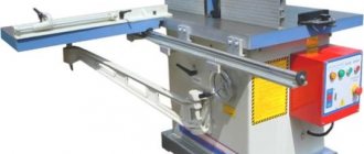
D300 combined woodworking machine. Purpose, scope
The woodworking combined machine D300 is designed for complex processing of joinery and simple furniture by sawing, planing (planing), milling with manual feeding of the workpiece in medium-sized enterprises.
With appropriate setup, the following types of processing can be performed D300
- planing (jointing) on a plane up to 320 mm in width and up to 4.3 mm in depth in one pass;
- planing along the ribs (edge) at an angle from 0 to 45°;
- one-sided thicknessing of boards, beams with mechanical feed up to 320 mm in width and up to 4.3 mm in depth;
- drilling, making longitudinal and transverse grooves using end mills on a drilling and slotting device.
- sawing along and across the fibers of boards up to 80 mm thick at a workpiece feed speed of up to 1.5 m/min;
- sawing along the fibers at an angle from 0 to 45° using a ruler;
- sawing slabs, boards across the grain (trimming) straight and at an angle using a miter carriage;
- milling with shaped cutters up to Ø180 mm;
- cutting tenons with shaped cutters using a carriage;
- curved milling with shaped cutters according to a template (copier upon request).
Planing spindle (knife shaft):
Saw spindle:
Milling vertical spindle:
Design features of the multifunctional machine D300
- Rigid bed and cast iron tables reduce vibration and ensure high machining accuracy for a long time
- Individual drive of sawing, planing and milling spindles from 3 electric motors
- High quality milling is ensured by a vertical high-speed spindle and a clamping system (optional)
- A miter carriage is used for cutting tenons and sawing across the grain and at an angle.
- The saw and milling shafts have the ability to move vertically and when one is working, the other is retracted to the lowest position and the hole is plugged
- Thicknessing with automatic feed through two drive shafts, while the planing tables are tilted, providing convenient access to the thicknessing table
- The drilling and grooving table provides movement: in a horizontal plane in any direction using a system of levers and vertically - with a screw with a handwheel and handle
- For safe operation, the machine is equipped with protective devices and guards: the protective casings have pipes for connecting chip ejectors
- The machine is equipped with eccentric clamps and guides.
- The machine has the ability to sharpen cutting tools (drills, cutters, etc.), as well as flat knives with a straight cutting edge for jointers and cylindrical cutters.
Operating conditions: in open areas, under a canopy, in enclosed spaces, except residential premises.
D300 machines must be operated under the following conditions:
- Altitude above sea level – up to 1000 m;
- Normal operating value of atmospheric pressure: 865…1065 GPa (650–800 mm Hg)
- Normal air temperature values during machine operation: +10°С ... +25°С
- Recommended air temperature +17°С … +23°С
- Recommended relative air humidity no more than 75% at 20 ºС
- Air humidity is allowed up to 85% at +25 °C and at lower temperatures, but without moisture condensation.
- Version according to the degree of protection from moisture - unprotected
Delivery set for the D300 machine
Complete machine
Box D300.052
Completeness:
- Tenoning carriage (assembled)
- Drill clamp (assembled)
- Corner
- Planing knives (installed on the machine)
- Circular saw 315x32 z=48 (supplied at additional cost)
- Saw casing with sectors
- Support kit (supplied at additional cost)
- Insert for circular saw
- Circular saw stop
- Milling device housing
- Milling device housing clamp
- Ring and sheet milling device
- Milling device stopper (installed on the machine)
- Planer guide (assembled)
- Planer protection (assembled)
- Drilling device (assembled)
- Drilling device mounting screws
- Manual
Additional accessories for the D300 machine
- D300K1 - Quick-detachable copying attachment for curved milling;
- D300FSh - Milling clamping device. Used to increase the productivity of the milling unit;
- automatic feeder - Automatic feeder;
- DS2200 - Aspiration system (chip suction).
Advantages and disadvantages
Household woodworking machines have a fairly large number of advantages, which determines their wide distribution. The advantages include the following:
- The operator has to do less work. When using hand tools, more effort is applied to obtain the required surface. In addition, planers may not be efficient to use because other operations may be required to complete the processing.
- By using universal woodworking machines, you can achieve higher quality of the resulting products. This is due to increased processing accuracy and a reduced degree of influence of the worker’s skills on the final result.
- Labor productivity increases significantly. A universal woodworking machine increases productivity several times. This is due to the fact that it takes less time to reposition the workpiece, and the machining process itself is as automated as possible. As the results show, with a competent approach, it can increase productivity by 7 times when compared with the case of using electric tools for wood processing.
Universal woodworking machine
This type of equipment also has several significant disadvantages:
- High price. By combining several components, the cost of the structure increases significantly.
- The equipment requires quite a lot of free space.
- Most household models are designed for processing small workpieces.
- When using a machine, it is often necessary to change tools to perform the next operation.
- There is no possibility of fully automating the process.
- Periodic professional maintenance is required.
- High energy consumption.
However, in mass production, the money spent on the purchase and installation of a multifunctional machine is justified.
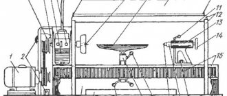
Design of the combined machine D300
Bed (D300.101.051) fig. 1.1. pos. 1.
The bed is a welded structure, which is the basis for the installation of circular saws, thickness planers, planers, milling and drilling devices. The frame is mounted on a flat, rigid plane and does not require a special foundation. The alignment of the bed is carried out according to the level in the longitudinal and transverse directions by adjusting the supports. The design of the frame provides for the possibility of installing the machine on vibration supports.
Assembly group "Reismus" (D300.200.001) fig. 1.1. pos. 3
The Reismus assembly group includes:
- thickness planer (D300.201.001)
- planing device (D300.202.001)
Thicknessing device (D300.201.001)
The thicknesser device consists of a knife shaft and a feed mechanism, which are mounted on two cast-iron jaws mounted on the frame; the lifting table is mounted directly on the frame. A device is also installed on the cheeks to prevent the workpiece from being thrown out towards the worker.
The knife shaft is the cutting organ of the device and is a steel cylinder with three planing knives fixed in its grooves. The knives are secured by means of clamping bolts and wedges that press the knives to the supporting planes of the shaft. The lower edge of the knives is supported by springs, which facilitates their alignment and adjustment. The knife shaft rotates in two ball bearings. Torque is transmitted to the knife shaft from an electric motor installed in the grooves of the side wall of the frame through a V-belt drive.
The belt is tensioned by vertical movement of the electric motor in the grooves.
The lifting table is mounted in the housing and installed directly on the frame. Lifting is carried out using a steering wheel.
The workpiece feeding mechanism consists of two shafts (feeding corrugated and receiving smooth), which are driven into rotation using a reduction gear-chain transmission. Power is taken off for mechanical feed from the knife shaft using a friction clutch (a spring-loaded rubber-coated wheel) mounted on one of the gear-chain shafts. The chain is tensioned by a spring-loaded sprocket.
The anti-blowout device (stops) is mounted on one of the links of the cast iron jaws. To set the height of the lifting table to the desired processing size, use a ruler with a pointer.
When working on the planer, the workpiece feed mechanism must be turned off using a lockable lever.
Adjustment and adjustment of the surface planer
The knives must be installed so that they protrude 1.5 mm beyond the dimensions of the knife shaft. When installing, control the uniform alignment of the knives along the entire length of the shaft.
Start tightening the bolts holding the knives from the middle of the wedge. Before starting work, be sure to check that the knives are securely fastened. After turning on the jointing device, make sure that it is operating normally and in the correct direction of rotation. It is necessary to monitor the operation of the knife shaft bearings. If the temperature rises, it is necessary to dismantle the bearings, wash and replace the lubricant.
Regularly monitor the tension of the workpiece feed mechanism chain and the condition of the rubber coating of the clutch drive wheel.
Note: when working on a thicknesser, the planing tables can be rotated on brackets if there is a protective cover for the knife shaft.
Planing device (D300.202.001) fig. 1.1. pos. 7
The planing device consists of a knife shaft, feed (front) and receiving (rear) planing tables, a guide ruler and protection of the knife shaft. The tables are mounted on the upper edges of the cheeks of the surface planer. The tables are height adjustable, which ensures the removal of chips of varying thicknesses from the material being processed. The rear table is set flush with the top point of the trajectory of the blades of the knife shaft using a ruler and is not subject to adjustment during operation.
The front table can be adjusted depending on the required thickness of chip removal. Lifting of tables is carried out by moving axes along the thread, rigidly connected to the tables.
The guide ruler is used to guide the material being processed and to plan edges at a certain angle (maximum angle 45°). The ruler is fixed with a clamp. The knife shaft guard is adjustable to the width of the material being processed. The electric drive is the same for thicknesser and planing devices.
Adjustment and adjustment of the planing device
Monitor the condition of table surfaces. Scourges and potholes must be eliminated. Ensure the reliability of the fastening elements of the guide ruler. The remaining requirements for adjusting and setting up the planing device are similar to clause 6.2.3. “Adjustment and adjustment of the thickness planer.”
Circular saw device (D300.401.001) fig. 1.1. pos. 2.
The circular saw device is used for longitudinal, transverse and cutting of material at an angle.
The device consists of a work table, a guide ruler, a rotating spindle with a circular saw.
The spindle body has the ability to move along the guides of the cast bracket, on which the table is rigidly fixed, and the bracket itself is attached to the bed.
A circular saw is installed on the spindle at one end, which is secured between the flanges with a nut; at the other end of the spindle there is a pulley, to which torque from the electric motor is transmitted using a V-belt.
The electric motor is mounted on a pendulum support, which is mounted on the side wall of the frame. The belt is tensioned by moving the pendulum support.
The cutting height is adjusted using a lever by moving the spindle body along the bracket guides and fixing it in the desired position.
The guide ruler installed on the table has the ability to move to adjust the width of the cut. To measure the width of the cut, a ruler is installed at the end of the table.
For cross-cutting and miter sawing, a tenoning carriage is used, moving along guides parallel to the plane of the saw. A stop angle for positioning the workpiece is installed on the carriage. To cut at an angle, the angle is rotated and fixed in the desired position.
The direction of rotation of the saw is towards the operator.
The circular saw is covered with a welded steel fence with a device that prevents the workpiece from being thrown out towards the operator.
A riving knife is installed at the back of the circular saw.
At the bottom of the casing there is a pipe for connecting a suction device for removing chips.
Adjustment and adjustment of the circular saw device
Place the circular saw on the shaft and securely tighten the nut through the flange. Check the direction of rotation of the saw at idle speed. Direction of rotation towards the operator. Check the reliability of the riving knife, the presence of the protective guard and its fastening. The gap between the knife along its entire length and the saw should not exceed 10 mm.
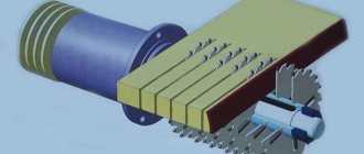
Milling device fig. 1.1. pos. 4 (tenon-cutting Fig. 1.1. item 5)
The milling (tenon-cutting) device consists of a housing flanged to the lower surface of the circular saw table. A quill moves inside the housing, in the bearings of which a milling spindle is installed. At the end of the spindle, cutters of various thicknesses and profiles are installed. For installation of cutters there is a set of spacer bushings. The tool is secured to the spindle using a nut. The spindle is extended into the working position and height adjusted by a manual drive consisting of a gear pair and a screw. In the working position, the spindle is fixed with a stopper.
The drive electric motor is installed on the sub-motor plate. The belt is tensioned by moving the plate on two rolling pins, which are fixed after adjustment.
The spindle rotation speed is changed by throwing the belt on double-strand pulleys.
The spindle with installed cutters is covered with a casing.
At the rear of the casing there is a pipe for connecting a suction device for removing chips. The milling depth is adjusted by moving the casing in the guide grooves (the milling device shown in Fig. 1.1 is not included in the machine set and is supplied at an additional cost).
A carriage with a table is used for cutting tenons. A stop angle with a clamp is installed on the table, allowing you to base and clamp the workpiece.
The angle has the ability to unfold, which allows you to cut tenons at different angles.
When working on a circular saw, the spindle of the milling (tenoning) device is set to its lowest position, and the hole in the table is closed with a special plug.
When working on a milling (tenoning) device, the circular saw of the circular saw must be installed in the lowest position and securely fixed, and its protective cover must be removed.
Adjustment and adjustment of the milling (tenon-cutting) device
Lower the circular saw blade to its lowest position and securely lock it.
Remove the plug on the table and extend the spindle into the working position. Install the cutter (set of cutters) onto the spindle using bushings and securely tighten it with a nut.
Install the fence with a guide bar (when milling) or without it (when cutting tenons) and adjust to the required size. Securely secure the fence. Set the cutter (set of cutters) to the required height by moving the spindle, and fix the quill.
Check the direction of rotation of the cutter at idle speed.
Direction of rotation towards the operator.
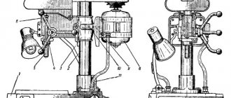
Drilling device fig. 1.1. pos. 6
The drilling device is used for drilling holes and milling grooves and recesses.
The drilling device consists of a table mounted on a bracket rigidly fixed to the cheek of the surface planer.
The table has the ability to move: vertically “up and down”, horizontally along the axis and perpendicular to the axis of the cutting tool. The table is moved: in height using a screw with a flywheel and handle, in the horizontal plane using a lever.
The table has a base support for the workpiece and a device for securing the workpiece.
Adjustment and adjustment of the drilling device
Install the drill chuck (not included in the delivery set) on the conical end of the knife shaft, surface planer, and secure with a screw.
Check the direction of rotation of the cartridge at idle.
Place the cutting tool in the chuck and tighten it.
Check the radial runout of the tool. If the runout is greater than 0.1 mm, replace the tool.
Make sure that the workpiece clamp works reliably.
Upon completion of work, remove the tool from the chuck.
Capabilities of universal machines
Depending on the number and type of units installed, woodworking equipment may have different capabilities. Multifunctional household woodworking machines can be used at home to carry out the following operations:
- Curvilinear, longitudinal or transverse cutting.
- Drilling holes of various diameters.
- Production of construction and other materials using the pressing method.
- Processing of workpieces on a plane: planing and grinding.
- Formation of complex shapes when using cutters.
- Sharpening and processing of cylindrical surfaces, creating a cone.
Multifunctional machines process workpieces of various types. In addition, there are mini woodworking machines on sale, which have less functionality but are highly mobile in use.
Electrical circuit diagram of the woodworking combined machine D300
Technical characteristics of the combined machine D300
| Parameter name | D-250 | D300 | D400 |
| Jointing (planing) | |||
| Maximum jointing (planing) width, mm | 250 | 320 | 410 |
| Maximum depth of layer removed in one pass when planing, mm | 5 | 4,3 | 4,3 |
| Diameter of the cutting part of the knife shaft, mm | 75 | 70 | 70 |
| Knife shaft rotation speed at idle speed, rpm | 4000 | 5600 | 5600 |
| Dimensions of planing knife, mm | |||
| Number of planing knives | 3 | 3 | 3 |
| Width of planing tables, mm | 250 | 320 | 410 |
| Total length of planing tables, mm | 1100 | 1420 | 1420 |
| Reismus | |||
| Maximum and minimum thickness of the workpiece during thicknessing, mm | 190..5 | 180..5 | 180..5 |
| Minimum length of workpiece processed during thicknessing, mm | 300 | 300 | 300 |
| Workpiece feed speed in thicknesser mode, m/min | 6 | 10 | 10 |
| Dimensions of the working surface of the thicknessing table, mm | 252 x 600 | 320 x 550 | 400 x 650 |
| Maximum thicknessing width, mm | 248 | ||
| Maximum thickness of the cut layer during thicknessing, mm | 2,5 | ||
| Lifting height of thicknesser table (maximum workpiece height), mm | 195 | 180 | 180 |
| Sawing. Circular saw device | |||
| Cutting depth range, mm | 1..70 | 1..80 | 1..80 |
| The largest diameter of the saw blade, mm | Ø250 x 33 x 3 | Ø250..Ø315 | Ø250..Ø315 |
| Saw mounting diameter, mm | 32 | 32, 50 | 32, 50 |
| Saw thickness, mm | 3 | 2 | 2 |
| Saw rotation speed, rpm | 4500 | 3500 | 3500 |
| Dimensions of the working surface of the saw table, mm | 980 x 470 | 750 x 500 | 750 x 500 |
| Dimensions of the end carriage, mm | 400 x 250 | ||
| Stroke of the end carriage, mm | 1080 | ||
| Vertical milling. Milling device | |||
| Vertical movement of the spindle (maximum thickness of the material being processed), mm | 80 | 80 | 80 |
| Mounting diameter of milling spindle, mm | 32 | 32 | 32 |
| Largest cutter diameter, mm | 144 | 180 | 180 |
| Milling spindle rotation speed, rpm | 4500 / 6500 | 6000 / 8000 | 6000 / 8000 |
| Dimensions of the working surface of the table, mm | 980 x 470 | 750 x 500 | 750 x 500 |
| Dimensions of the working surface of the tenoning carriage, mm | 250 x 400 | 335 x 450 | 335 x 450 |
| Maximum carriage stroke, mm | 1080 | 900 | 900 |
| Drilling. End milling | |||
| Maximum diameter of drill, cutter, mm | 16 | 16 | 16 |
| Rotation speed of drill, cutter, min | 4500 | 5600 | 5600 |
| Dimensions of the working surface of the table, mm | 365 x 150 | 450 x 250 | 450 x 250 |
| Drilling depth, mm | 100 | 150 | 150 |
| Longitudinal travel of the table, mm | 150 | 150 | 150 |
| Electrical equipment of the machine | |||
| Type of supply current | 220V / 380V 50Hz | 380V 50Hz | 380V 50Hz |
| Number of electric motors on the machine, pcs. | 3 | 3 | 3 |
| Electric motor of planing, thicknessing, drilling device, kW | 1,5 | 2,2 | 2,2 |
| Electric motor of circular saw, kW | 1,5 | 3,0 | 3,0 |
| Electric motor of vertical milling device, kW | 1,4 | 3,0 | 3,0 |
| Total power of electric motors, kW | 4,4 | 8,2 | 8,2 |
| Dimensions and weight of the machine | |||
| Machine dimensions (length x width x height), mm | 1260 x 1140 x 970 | 1660 x 1500 x 1100 | 2050 x 1560 x 1100 |
| Machine weight, kg | 304/355 | 650 | 750 |
Related Links. Additional Information
- Directory of woodworking machines
- Manufacturers of woodworking machines and equipment
- Manufacturers of household woodworking machines
- Manufacturers of chipping machines
- Classification of woodworking machines
- Machines for longitudinal cutting of lumber
- Sawmill frames. Classification
- Lumber. Basic concepts. Terms and Definitions
Home About the company News Articles Price list Contacts Reference information Interesting video KPO woodworking machines Manufacturers
Types of universal machines
Woodworking machines for home or industrial use can be classified according to a large number of different characteristics, among which we note their functional purpose. On the market you can find a universal wood cutting machine that has the following functions:
- Sawing A belt woodworking machine is found in almost every private workshop. The same function can be part of multifunctional equipment. The cut can be carried out along a straight or curved path. A circular planing woodworking machine is an integral part of almost any workshop.
- Pressing. Household machines can also be used for the production of various materials from solid wood. The press significantly increases the density of bulk heterogeneous material.
- Planing. A wood planing machine is used to obtain a plane with specified parameters. Such equipment is used extremely often in the manufacture of tabletops or other furniture elements. The combined model can replace wood jointers, as it combines all the necessary functions.
Wood planer
- Drilling. Often, when making cabinets and other similar products, it is necessary to create a through or blind hole. To do this, you can use a separate drilling machine or purchase the one in question. It is worth considering that in the first case a carpenter's vice is required, in the second case fastening is carried out using a special clamping device.
- Milling. The woodworking milling machine has become quite widespread. It can be used to process flat or curved surfaces, as well as form various grooves. Due to the large number of different cutter options, the scope of application of universal woodworking machines increases significantly.
- Cylindrical turning. The lathe is very common because it is used to produce cylindrical products. That is why a desktop woodworking machine can have units that allow turning.
- Grinding. To give the surface special performance qualities, grinding can be carried out. In this case, the carpentry machine is equipped with a unit that allows the installation of a grinding wheel of different diameters.
Woodworking Sanding Machine
If necessary, the most suitable version of the machine is selected. For example, in some cases, milling is not carried out often, and due to the presence of this unit, the cost of the product increases significantly.
It is worth considering that as the number of components and functionality of the machine increases, its cost increases significantly.
Classification is also carried out by area of application:
- Specialized. Similar versions are purchased to perform precision machining and are installed at large plants. The equipment of this group is characterized by high functionality and performance. Many models are also characterized by the presence of additional options.
- Universal. Equipment of this group is found extremely often in home workshops and on small production lines. The functionality of the equipment is at a fairly high level. Note that such machines are ideal for high-quality processing. The cost of the offer is quite high. The possibility of installation in domestic conditions can be associated with compact dimensions.
- Household models. This group is the cheapest and is intended for installation in home workshops. Features include the fact that at a low price, the equipment can last a long time; the device is suitable for installation at home.
Household woodworking machine
For home use, it is recommended to choose models from the third or second group. As a rule, they are easy to maintain and can be installed on a 220V network.