Unbalance of any rotating part
Failure of a diesel locomotive can occur both during operation due to uneven wear, bending, accumulation of contaminants in any one place, when the balancing weight is lost, and during the repair process due to improper processing of the part (displacement of the axis of rotation) or inaccurate alignment of the shafts.
To balance the parts, they are subjected to balancing. There are two types of balancing
: static and dynamic.
Rice. 1. Scheme of static balancing of parts:
T1 is the mass of the unbalanced part; T2 is the mass of the balancing load;
L1, L2 - their distances from the axis of rotation.
Static balancing.
For an unbalanced part, its mass is located asymmetrically relative to the axis of rotation. Therefore, in the static position of such a part, i.e. when it is at rest, the center of gravity will tend to take a lower position (Fig. 1). To balance the part, a load of mass T2 is added from the diametrically opposite side so that its moment T2L2 is equal to the moment of the unbalanced mass T1L1. Under this condition, the part will be in balance in any position, since its center of gravity will lie on the axis of rotation. Equilibrium can also be achieved by removing part of the metal of the part by drilling, sawing or milling from the side of the unbalanced mass T1. In the drawings of parts and in the Repair Rules, a tolerance is given for balancing parts, which is called imbalance (g/cm).
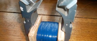
Flat parts that have a small length-to-diameter ratio are subjected to static balancing: the gear wheel of a traction gearbox, the impeller of a refrigerator fan, etc. Static balancing is carried out on horizontally parallel prisms, cylindrical rods or on roller supports. The surfaces of prisms, rods and rollers must be carefully processed. The accuracy of static balancing largely depends on the condition of the surfaces of these parts.
Dynamic balancing.
Dynamic balancing is usually carried out on parts whose length is equal to or greater than their diameter. In Fig. Figure 2 shows a statically balanced rotor, in which mass T is balanced by a load of mass M. This rotor, when rotating slowly, will be in equilibrium in any position. However, with its rapid rotation, two equal but oppositely directed centrifugal forces F1 and F2 will arise. In this case, a moment FJU is formed which tends to rotate the rotor axis at a certain angle around its center of gravity, i.e. dynamic imbalance of the rotor is observed with all the ensuing consequences (vibration, uneven wear, etc.). The moment of this pair of forces can only be balanced by another pair of forces acting in the same plane and creating an equal reaction moment.
To do this, in our example, we need to apply two weights of masses Wx = m2 to the rotor in the same plane (vertical) at an equal distance from the axis of rotation. The loads and their distances from the axis of rotation are selected so that the centrifugal forces from these loads create a moment /y counteracting the moment FJi and balancing it. Most often, balancing weights are attached to the end planes of parts or part of the metal is removed from these planes.
Rice. 2. Scheme of dynamic balancing of parts:
T—rotor mass; M is the mass of the balancing load; F1, F2 - unbalanced, reduced to the rotor mass planes; m1,m2 - balanced, reduced to the rotor mass planes; P1 P 2 - balancing centrifugal forces;
When repairing diesel locomotives, dynamic balancing is carried out on such fast-rotating parts as a turbocharger rotor, the armature of a traction motor or other electric machine, a blower impeller assembled with a drive gear, a water pump shaft assembled with an impeller and a gear wheel, and drive shafts of power mechanisms.
Rice. 3. Diagram of a console-type balancing machine:
1 - spring; 2 — indicator; 3 anchor; 4 - frame; 5 — machine support; 6 — bed support;
I, II - planes
Dynamic balancing is in progress
on balancing machines. The schematic diagram of such a console-type machine is shown in Fig. 3. Balancing, for example, the armature of a traction motor is carried out in this order. The anchor 3 is placed on the supports of the swinging frame 4. The frame rests with one point on the support of the machine 5, and the other on the spring 1. When the armature rotates, the unbalanced mass of any of its sections (except for the masses lying in plane II - II) causes the frame to swing. The amplitude of frame vibration is recorded by indicator 2.
In order to balance the anchor in the I-I plane, test loads of different masses are attached alternately to its end on the side of the collector (to the pressure cone) and the frame oscillations are stopped or reduced to an acceptable value. Then the anchor is turned over so that plane I—I passes through the fixed support of the frame 6, and the same operations are repeated for plane II—II. In this case, the balancing weight is attached to the rear pressure washer of the armature.
After completion of all assembly work, the parts of the selected sets are marked (with letters or numbers) in accordance with the requirements of the drawings
As is known, an electric motor (hereinafter referred to as an electric motor) consists of two elements - static (stator) and moving (rotor). The latter, during operation, can rotate at a very high speed, which amounts to thousands and tens of thousands of revolutions per minute.
Rotor imbalance not only leads to increased vibration, but can also damage the rotor itself or the entire electric motor. Also, due to this problem, the risk of breakdown of the entire installation where this ED is used increases.
To avoid these negative consequences, electric motor armatures are balanced
- also known as “rotor balancing” or “electric motor balancing”.
How to balance electric motor rotors
A balanced rotor is a rotor whose axis of rotation coincides with the axis of inertia. True, absolute balance can only be achieved in an ideal world, but in reality there is always at least a slight “distortion”. And the task of balancing is to minimize it.
There are static and dynamic balancing of rotors.
Static rotor balancing is designed to eliminate significant mass imbalance relative to the axis of rotation. It can be done at home because it does not require the use of special equipment. Prismatic or disc clamps are sufficient. This operation can also be performed using specially designed lever scales.
The rotor is placed on a prismatic or disk clamp. After this, its heaviest side outweighs, and the part scrolls down. Make a mark with chalk at the lowest point. Then the rotor is rolled four more times, and after each final stop, the lowest point is noted.
When there are five marks on the rotor, measure the distance between the outer ones and make a sixth one in the middle. Then, a balancing weight is installed at the diametrically opposite point of this sixth mark (the point of maximum imbalance).
The weight of the load is selected experimentally. At the point opposite to the maximum imbalance, weights of various masses are installed, after which the rotor rotates and stops in any position. If there is still an imbalance, the weight of the weight decreases or increases (depending on which direction the rotor turns after stopping). The task is to select such a mass of weighting material that the rotor does not turn after stopping in any position.
After determining the required mass, you can either leave the weight or simply drill a hole at the resulting sixth point - the point with maximum imbalance. In this case, the mass of the drilled metal must correspond to the mass of the selected load.
-yourself static
quite rough and is designed to eliminate only serious distortions in the mass of the load on the shaft.
There are other disadvantages as well. Thus, static balancing of an electric motor armature with your own hands
will require numerous measurements and calculations. To improve accuracy and speed, it is recommended to use the dynamic method.
To do this, you will need a special machine for balancing electric motor rotors.
.
It spins the shaft placed on it and determines along which of the axes the mass is skewed. Dynamic balancing of electric motor rotors
can eliminate even the smallest deviations of the axis of inertia from the axis of rotation.
Dynamic balancing of the motor shaft
produced by computer method. The highly intelligent equipment that is used for this process is able to independently suggest which counterweight should be installed on which side.
However, finding a machine for balancing a very heavy or large rotor is quite difficult. Typically, the dynamic method of eliminating distortion is used for relatively small electric motors, regardless of power. Therefore, when choosing methods for balancing and aligning electric motors
, it is worth paying attention not only to the accuracy of the operation, but also to the physical ability to carry out this process for the existing shaft.
Most machine tools at repair plants are designed on the principle of measuring the magnitude of the imbalance vector by the maximum deflection of the supports at resonant rotation frequencies. This measures the magnitude of the vector. The direction of the vector is fixed by the tracking system according to the angle of rotation of the body of rotation being tested. The indicators are summarized in the measuring device, according to the mutual reaction of the device coils, according to the principle of an electrodynamic wattmeter.
Initially, the existing imbalance is measured. Its correction consists of installing balancing weights provided for in the product drawing in the direction directly opposite to the measured vector. Or in a small removal of metal in the direction strictly corresponding to the measured vector.
Loads, depending on the design of the unit, are secured temporarily or permanently. The vector is re-measured and the installed weights are adjusted, or they are finally secured as provided by the design, if the value of the residual imbalance corresponds to the permissible
Serially produced dynamic balancing machines
Machines produced by the Minsk Machine Tool Plant, types 9717, 9718, 9719, are very widely used. This equipment has significant dimensions and requires large volumes of reinforced concrete foundations for installation. They carry out balancing of parts and assembly units from 0.5 to 5.0 tons. These are the anchors of electric cars and wheel pairs. Since the mid-80s, the design of generator armature flanges has been changed. The outer surface of the socket for installing the centering ring is made in the form of an elongated cylindrical collar, which can directly serve as a base surface for dynamic balancing of the armature. This made it possible to avoid installing additional bushings, reduce the complexity of the operation and increase its accuracy.
Fig. 20 Balancing the armature on the 9719 machine
New generation of machines
Recently, factories have introduced a new generation of balancing machines offered on the market today. In particular, these are machines. A special feature of the machines is that the imbalance is measured not due to the maximum deflection of the moving bearing supports, but due to the reaction of the rigidly fixed supports. In this case, the reaction itself is measured as a stress value using a strain gauge method using built-in sensors. All results are summarized and processed on a computer built into the machine with information displayed on the display.
This machine design does not require foundations for its installation. The machine is installed directly on the floor surface. The dimensions of these machines are slightly larger than the dimensions of the product being balanced.
Fig. 21 Dynamic balancing on the VM3000 machine from DIAMECH
A very characteristic detail for new generation machines is the absence of a foundation and the transmission of rotation of the part by a belt drive.
Often, after prolonged use, electric motors develop extraneous noise or increased vibration. These signs indicate an imbalance. In good condition, the axis of inertia of the rotor should coincide with the axis of rotation, however, during long-term operation and after possible overloads, these axes may shift. That is why it is necessary to carry out regular diagnostics of electric motors. LLC "VER" provides services not only for diagnostics, but also for balancing of electric motors of any type at reasonable prices and in the shortest possible time.
One of them is balancing the armature of electric motors. It is produced using special equipment that allows one to calculate the smallest deviations in the rotation of the rotor. After minor adjustments, the engines are again ready for further use. Let's figure out what balancing the armature rotors of electric motors is and why it is carried out.
Angler anchor device
The armature of an angle grinder motor is a conductive winding and a magnetic circuit into which the rotation shaft is pressed. It has a driven gear at one end and a commutator with lamellas at the other. The magnetic core consists of grooves and soft plates coated with varnish to insulate each other.
Two conductors of the armature winding are laid in the grooves according to a special pattern. The conductor makes up half of the turn, the ends of which are connected in pairs on lamellas. The beginning of the first turn and the end of the last are in the same groove, therefore they are closed to one lamella.
How to check the angle grinder's anchor for serviceability
Types of anchor defects:
- An insulation breakdown to ground is a short circuit of the winding to the iron rotor body. Occurs due to destruction of insulation.
- Wiring of collector terminals.
- Uneven wear of the commutator.
- visually;
- multimeter;
- light bulb;
- special devices.
If the armature is faulty, the motor overheats, the winding insulation melts, and the turns short-circuit. The contacts connecting the armature winding to the collector plates are unsoldered. The current supply stops and the engine stops working.
Types of armature diagnostics:
Complex loop winding
If it is necessary to obtain an even larger number of parallel branches, a complex armature loop winding is used (Fig. 13.8). Such a winding contains two simple loop windings (m = 2), so the number of parallel branches is doubled , i.e. 2a = 2 * 2p = 4p . Such windings are necessary in machines of significant power at low network voltage: 12; 24; 48 V.
In order for the distribution of currents in the parallel branches of the armature winding to be the same, it is necessary that the electrical resistance of these branches does not differ from each other and that the emf induced in the sections that make up each parallel branch are the same. If these conditions are not met, equalizing currents appear between the parallel branches, disrupting the operation of the brush-collector contact.
The exception is a simple wave winding , the sections of which are evenly distributed under all poles of the machine, so the magnetic unsymmetry of the machine does not cause equalizing currents to appear in this winding. As for simple loop and all types of complex armature windings, there are always reasons for the appearance of equalizing currents in them. This leads to the need to use so-called equalizing connections in these windings, through which equalizing currents are closed, relieving the brush-collector contact from overload. Equalizing connections complicate the manufacture of the armature winding and lead to additional consumption of winding copper.
Standard diagnostics
While you take the diagnostic device, inspect the anchor. This is where damage happens. If the wiring is melted, the burnt insulating varnish will leave black marks, also known as a specific smell. There are bent and crumpled turns or conductive particles, for example, solder residues. These particles are a prerequisite for a short circuit
between the turns. The lamellas have curved edges, called cocks, to connect to the winding.
Due to disruption of these contacts, the lamellas burn out.
Other damage to the collector: raised, worn or burnt plates. Graphite from the brushes can accumulate between the lamellas, which also indicates a short circuit.
How to check with a multimeter
- Set the resistance to 200 ohms. Connect the probes of the device with 2 adjacent lamellas. If the resistance is uniform between all adjacent plates, it means the winding is working. If the resistance is less than 1 ohm and very close to zero, there is a short circuit
between the turns. If the resistance is two or more times higher than average, it means that the winding turns are broken. When there is a break, the resistance is so great that the device goes off scale. On an analog multimeter, the needle will go all the way to the right. But digital won’t show anything.
Prices for repairing an electric motor armature
| Power, kWt) | Rotation speed, rpm | |||
| 3000 | 1500 | 1000 | 750 | |
| Up to 1.5 | 2740 | 2806 | 3417 | 4057 |
| 2.2 | 3090 | 3245 | 4154 | 4897 |
| 3 | 3642 | 3901 | 4973 | 5179 |
| 4 | 5012 | 4652 | 5413 | 6804 |
| 5.5 | 5296 | 5301 | 5978 | 7511 |
| 7.5 | 6630 | 6919 | 7312 | 11021 |
| 11 | 8139 | 8147 | 9937 | 13182 |
| 15 | 12088 | 12049 | 11737 | 14803 |
| 18,5 | 13001 | 13345 | 15217 | 24450 |
| 22 | 15057 | 15805 | 23408 | 25522 |
| 30 | 17648 | 18202 | 25857 | 29275 |
| 37 | 23803 | 25949 | 30677 | 40080 |
| 45 | 29055 | 28737 | 38389 | 48070 |
| 55 | 34546 | 32811 | 41481 | 60759 |
| 75 | 44670 | 48812 | 64472 | 82899 |
| 90 | 47893 | 51078 | 78166 | 99898 |
| 110 | 67202 | 73052 | 95759 | 122517 |
| 132 | 80848 | 87962 | 114110 | 147423 |
| 160 | 98012 | 106439 | 138740 | 179116 |
| 200 | 123101 | 132548 | 173924 | ———- |
| 250 | 154120 | 167435 | ———- | ——— |
| 320 | 237156 | ————— | ———- | ———— |
| kW | 3000 rpm | 1500 rpm | 1000 rpm | 750 rpm |
COEFFICIENTS USED IN THE CALCULATION:
Source
How to check the rotor of an angle grinder using a light bulb
- Take two wires and connect them to the lamp.
- Make a break on the negative wire.
- Apply voltage to the wires. Place the ends of the break against the collector plates and rotate it. If the light bulb glows without changing brightness, it means there is no short circuit.
- Perform a short circuit test to the iron. Connect one wire to the lamellas and the other to the rotor iron. Later with the shaft. If the light bulb glows, it means there is a ground fault. The winding closes to the rotor housing or shaft.
This procedure is similar to diagnostics with a multimeter.
Checking with a short-circuited turns indicator (SCI)
There are some anchors where you don’t see the wires connected to the collector due to being filled with an opaque compound or because of a bandage. Therefore, it is difficult to find the commutation on the collector relative to the grooves. An indicator of short-circuited turns will help here.
This rumored device is small in size and easy to operate.
First check the anchor for breaks. Otherwise, the indicator will not be able to find a short circuit
. For this purpose, use a tester to determine the resistance between 2 adjacent lamellas. If the resistance exceeds the average by at least twice, it means, of course, a break. If there is no break, move on to the next step.
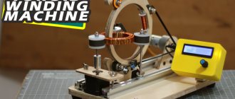
Rewinding the vacuum cleaner armature
.
The resistance regulator allows you to select the sensitivity of the device. It has two lights: reddish and green. Adjust the regulator so that the reddish light starts to glow. On the indicator body there are two sensors such as snow-white dots, located 3 centimeters far from their native edge. Attach the indicator with the sensors to the winding. Rotate the anchor slowly. If the reddish light comes on, it means, of course, that there is a short circuit .
Diagnostics with an armature testing device (throttle)
The armature testing device determines the presence of an interturn short circuit in the winding. A choke is a transformer that has only a primary winding and a magnetic gap cut out in the core.
When we place the rotor in the gap, its winding begins to work like the secondary winding of a transformer. Turn on the device and place an iron plate on the anchor, for example, an iron ruler or a hacksaw blade. If there is an interturn short circuit, the plate will vibrate or be magnetized towards the armature body due to local oversaturation of iron. Rotate the armature around the axis, moving the plate so that it lies on different turns. If there is no short circuit, the plate will move freely along the rotor.
Possible malfunctions of the commutator motor
Sometimes even people familiar with the structure of the mechanism have little idea how to check a commutator motor. Below we will talk about all possible malfunctions and ways to identify and eliminate them.
Broken contacts. This is indicated by active sparking. Interturn short circuit (short circuit of windings in the collector). It also causes sparking. Wear of the brush-collector unit. At the same time, it turns black and sparking appears. Usually the problem is solved by replacing old elements with new ones. To remove the assembly, move the lock and unscrew the mounting bolt (depending on the engine model). Darkening of the contact part of the collector. Often it is enough to clean it with fine sandpaper. Formation of a groove at the point of contact of the brushes with the commutator. It is necessary to perform the grooving of the unit on the machine. Bearing wear. This malfunction can be determined by increased vibration of the housing during engine operation and beating of the cartridge. In this case, bearing replacement is required. The armature touches the stator. Sometimes replacing the armature is enough, but in some cases you will have to replace both the armature and the stator. Control failure on the microcontroller. Installing a new microcontroller is the optimal solution to the problem. Burnout or breakage of windings
Pay attention to their color and integrity. Blackening of the entire winding body or part thereof indicates burnout; a break is easily determined by visual inspection
In this case, they need to be replaced or rewinded. Graphite dust in the space between the lamellas. Your appliance just needs cleaning. Burnout of wire insulation. A characteristic odor will indicate this problem.
In all of the above cases, restoring the electric motor manifold with your own hands is quite possible if you have the necessary spare parts and tools. Only if you do not have experience in rewinding windings, it is better to contact the appropriate service. After troubleshooting, reconnect all parts in reverse order.
How to repair an anchor at home
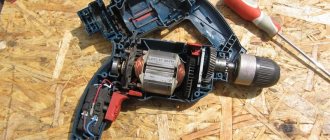
The third part of screwdriver breakdowns occurs due to the anchor. With daily busy work, malfunctions occur as early as the first six months, for example, due to untimely replacement of brushes. With gentle use, the screwdriver will last a year or more.
Of course, the anchor can be saved if the balance is not disturbed. If during operation of the device you hear an intermittent rumble and powerful vibration, then this is an imbalance. Such an anchor must be replaced. There is an option to repair the winding and commutator. Small short circuits are eliminated. If a significant part of the winding is damaged, of course, rewind it. Grind worn and very damaged lamellas, build them up and solder them in another way. In addition, there is no point in undertaking anchor repairs if you are unsure of your own abilities. It is better to change it or take it to a workshop.
In what cases can you save an anchor and restore it yourself?
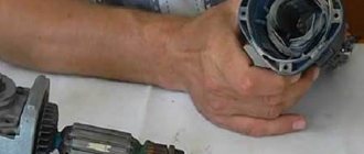
If damage to the armature is determined with guaranteed accuracy, the part must be removed from the electric motor. Disassembling the motor must be done with special care, after removing the brushes and disconnecting the power terminals. The rotor is removed along with the support bearings and the motor cooling impeller; they form a single whole with it.
If most of the wiring in the armature is damaged and the balancing is disrupted as a result of overheating, it is better to replace it entirely. An imbalance is indicated by increased vibration and an uneven hum when the mechanism operates.
How to rewind an anchor - step-by-step instructions
If the balancing of the armature is not disturbed, and the problem is only in damaged windings, then such an armature can be restored independently by rewinding the coils. Rewinding a rotor at home requires a lot of patience and accuracy.
The technician must have skills in working with a soldering iron and instruments for diagnosing electrical circuits. If you are unsure of your abilities, it is better to take the engine to a workshop for repairs or replace the entire armature yourself.
To rewind the anchor yourself you will need:
- wire for a new winding. A copper core with a diameter exactly matching the old conductor is used;
- dielectric paper for insulating the winding from the core;
- varnish for filling coils;
- soldering iron with tin-lead solder and rosin.
Before rewinding, it is important to count the number of turns of wire in the winding and wind the same amount of new conductor onto the coils.
The rewinding process consists of the following steps:
- Dismantling old windings. They must be carefully removed without damaging the metal body of the armature. If any burrs or damage are found on the body, they must be smoothed out with a file or sanded with emery. Sometimes, to completely clean the body of slag, craftsmen prefer to burn it with a torch.
- Preparing the collector for connecting a new wire. There is no need to remove the manifold. You should inspect the lamellas and measure the resistance of the contacts in relation to the housing with a megger or multimeter. It should be no more than 0.25 MOhm.
- Removing old wiring on the manifold. Carefully remove the remaining wires and cut grooves in the contacts. In the future, the ends of the coil wires will be inserted into the grooves.
- Installation of sleeves for anchors. The sleeves are made of dielectric material 0.3 mm thick, for example, electrical cardboard. Cut a certain number of sleeves and insert them into the grooves of the cleaned anchor.
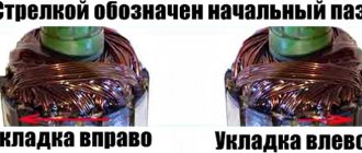
- Rewinding reels. The end of the new conductor is soldered to the end of the lamella and wound in successive circular movements, counterclockwise. This laying is called “laying to the right.” Winding Repeat for all coils. Near the collector, tie the wires together with a thick thread of cotton fabric (it is prohibited to use nylon, as it melts when heated).
- Checking the winding quality. After laying all the windings, check with a multimeter for the absence of interturn short circuits and possible breaks.
- Finishing processing. Treat the finished coil with varnish or epoxy resin to secure the winding. In factory conditions, the impregnation is dried in special ovens. You can do this at home in the oven. As an option, use quick-drying varnishes for impregnation, applying the coating in several layers.
How to rewind an anchor
Before disassembling the armature, write down or sketch the direction of the winding. It is perhaps on the left as it is also called on the right. To find it correctly, look at the end of the armature of an unfamiliar collector. Wear gloves and take sharp wire cutters or a hacksaw. Remove the winding end parts. The collector needs to be cleaned, but it is not necessary to remove it. Carefully, without damaging the slot insulators, knock out the rods of the remaining parts of the winding using a hammer and an iron chisel.
Video: Removing the winding
Using a needle file, without damaging the insulator film, remove the remaining impregnation. Count the conductors in the slot. Calculate the number of turns in the section and determine the diameter of the wire. Draw a diagram. Cut cardboard sleeves for insulation and stick them into the grooves.
Video: Winding left and right
After winding, weld the leads of the sections with the manifold cocks. Now check the winding with a tester and short circuit
. Proceed with impregnation.
Abstract on impregnation (taking into account the speed controller)
- Once you are sure there are no problems, send the armature to the electric oven to warm up for the best flow of the epoxy.
- After warming up, place the anchor on the table at an angle for better spreading over the wires. Apply resin to the frontal part and slowly turn the anchor. Drip in anticipation of the glue on the back of the frontal part.
To complete the process, sharpen the commutator slightly. Balance the anchor using a dynamic balancer and an angle grinder. Now grind completely on the bearing. You need to clean the grooves between the lamellas and polish the collector. Make a final check for opens and shorts.
The peculiarity of the winding for angle grinders with adjustable speed is the fact that the rotor is wound with power reserves. Current density affects the number of revolutions. The wire cross-section is too high and the number of turns is too low.
Replacing the anchor yourself at home
Practice shows that if you decide to replace the armature of an angle grinder, then it is best to change it together with the support bearings and the engine cooling impeller.
To replace you will need:
- New angle grinder anchor. Must match your model. Interchange with other models is not permitted.
- Screwdrivers, wrenches.
- A soft brush and cloth for wiping the mechanism.
How to remove an anchor
Replacing the anchor begins with disassembling the angle grinder. The following steps are performed:
- Use a screwdriver to unscrew the brush units on both sides. The brushes are removed.
Video: replacing bearings on an angle grinder
How to put an anchor in place
To install a new angle grinder anchor in place, you should take a new part, and then assemble the tool in the reverse order. The sequence of actions is as follows:
- A fixation disk is installed on the armature shaft.
- The bearing is installed using the pressing method.
- The small gear is fitted and secured with a retaining ring.
- The anchor is inserted into the gearbox housing, and the docking holes are aligned.
- The gearbox mounting bolts are tightened.
- The anchor with the gearbox is inserted into the body of the angle grinder and fixed.
- The brushes are deposited in their places and closed with lids.
After completing these steps, the grinder is ready for work. The anchor has been replaced.
Video: how to check an angle grinder
An ancient Sufi wisdom says: “A smart person is one who is able to come out of a difficult situation with dignity. But the one who does not find himself in such a situation is wise.” By following the rules for operating household appliances and preventing the motor from overheating, you can avoid breakdowns and troubles in the operation of the angle grinder. Keeping and storing the tool clean and dry will prevent its mechanisms from contamination and oxidation of current-carrying elements. Timely maintenance of the tool is guaranteed to eliminate unpleasant surprises during operation.
In many household devices and home-made structures, low-power electric machines are used as a drive. Despite the high reliability of electric motors, their failure for a number of reasons is not uncommon. Given the relatively high cost of these devices, it is more practical to repair them rather than replace them. We suggest considering the possibility of rewinding electric motors at home.
Repair: Elimination of insulation breakdown
If the insulation breakdown was small and you found it, you need to clean the area from carbon deposits and check the resistance. If its value is normal, insulate the wires with asbestos. Apply quick-drying “Super Moment” type glue on top. It will seep through the asbestos and insulate the wire perfectly.
If you still haven’t found the location of the insulation breakdown, then try to carefully saturate the winding with impregnating electrical insulating varnish. Punched and unpierced insulation will be saturated with this varnish and become stronger. Dry the anchor in a gas oven at about 150 degrees. If this does not help, try to rewind the winding or change the armature.
Anchor change
Replacing the armature on an angle grinder is carried out simultaneously with replacing the support bearings and the motor cooling impeller. To perform this you will need the following equipment:
- a new anchor for an angle grinder, suitable specifically for your device;
- screwdriver and wrench;
- a brush with soft bristles and a cloth for wiping elements.
Disassembly steps:
- removing brushes;
- unscrewing the gearbox;
- removing the gearbox cover;
- removing the ring that secures the small gear to the armature;
- removing the armature together with the gear and bearing;
- removing the bearing using a special removable device;
- removing the gear and fastening disk;
- wiping the main elements with a napkin.
Installing a new part for the grinding machine is carried out in the reverse order:
- installing the securing disk on the shaft;
- bearing pressing;
- installing a small gear and securing it with a retaining ring;
- placing the anchor in the gearbox with connecting holes;
- securing the gearbox in the angle grinder body;
- installation of brushes;
- device check.
Thus, repairing an anchor with your own hands can be done quickly and easily. But in order to prevent such cases, you need to use the device carefully and not subject it to prolonged high loads. Keeping the tool in a dry place and taking the necessary care will extend its service life.
Soldering the collector plates
The slats are installed on a plastic base. They are usually erased to the very base. Only the edges remain that the brushes cannot reach.
Such a collector can be returned by soldering.
- Cut the required number of lamellas to size from a copper pipe or plate.
- When the armature of copper residues, solder it with ordinary tin and soldering acid.
- When our client is left with the lamellas soldered, do some sanding and polishing. If you don't have a lathe, use a drill or screwdriver. Insert the armature shaft into the chuck. Sand first with ratfil. Polish later with fine sandpaper. Don’t forget to clean the grooves between the slats and measure the resistance.
- There are lamellas that are not completely damaged. To return them, you need to carry out more painstaking preparation. Lightly grind the commutator to clean the records.
Source
Features of repair of commutator drives
This type of electric machine is more likely to experience mechanical failures. For example, brushes worn out or commutator contacts clogged. In such situations, repairs come down to cleaning the contact mechanism or replacing graphite brushes.
Read also: How to charge the battery from your phone
Testing the electrical part comes down to checking the resistance of the armature winding. In this case, the probes of the device are applied to two adjacent contacts (lamellas) of the collector, after taking readings, measurements are taken further in a circle.
Checking the armature winding of a commutator motor
The displayed resistance should be approximately the same (taking into account the instrument error). If a serious deviation is observed, then this indicates that there is an interturn short circuit or open circuit, therefore, rewinding is necessary.