Information about the manufacturer of the profile grinding machine 395M
Manufacturer of the universal profile grinding machine 395M is the Leningrad Machine Tool Plant named after. Ilyich , founded in 1924.
Since 1984, the Ilyich plant has been a member of the Association of Precision Machine Tools as the parent enterprise, and since 1993 it has been registered as the St. Petersburg Precision Machine Tools Plant, SPZPS .
Machine tools produced by the Leningrad Machine Tool Plant named after. Ilyich.
Currently, the St. Petersburg Precision Machine Tool Plant, SPZPS
- 3a10p
cylindrical grinding machine Ø 15 - 312m
cylindrical grinding machine Ø 200 x 500 - 395M
profile grinding machine 20 x 20 - 395MF10
profile grinding machine with digital display 20 x 20 - 3951VF1
profile grinding machine with digital display 50 x 50 - V-88
cylindrical grinding machine Ø 140 - LA155f30
- CNC longitudinal turning lathe Ø 16
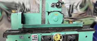
395M optical profile grinding machine. Purpose and scope
395M optical profile grinding machine was accepted for serial production in 1963, and in 1978 it was replaced by a more advanced model 395M-1.
The optical profile grinding machine 395M is designed for high-precision grinding of complex profiles limited by straight lines, circular arcs and curves of various shapes, and the material of the workpiece can be hardened.
The main feature of the 395M is the presence of a screen on which the workpieces and the grinding wheel are projected in a 50:1 enlarged view using a special optical projection device.
A drawing of the part on tracing paper at a scale of 50:1 is superimposed on the screen. Processing is carried out by combining the image of the circle with the outline of the drawing. The movement of the grinding wheel supports along the profile is carried out manually or mechanically using DC electric motors, the speed of which is controlled using rheostats.
The reciprocating movement of the grinding wheel slide is carried out automatically using an electric motor through a rocker mechanism. After grinding, the treated surfaces are finished.
Methods and features of profile grinding
Profile grinding machines are designed for grinding surfaces that have a curved or broken line. The processing process on such machines is called profile grinding .
This method is usually used to produce equipment, shaped cutting tools, copiers, templates, patterns, etc., much less often - machine parts. Depending on the pattern of shaping the surface being processed, profile grinding machines can be divided into two groups:
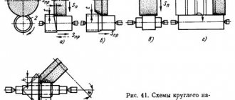
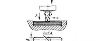
- Machines that process the surface at a given relative movement of the wheel and the workpiece (Fig. 10.12 - with kinematic profiling)
- Machines that process the surface by copying a pre-profiled grinding wheel
In the first case, the profile of the surface being processed is created by moving the circle along line a (see Fig. 10.12), called the generatrix of the profile, and along line 1, called the guide. The generatrix is reproduced in a vertical plane during the reciprocating movement of the grinding wheel relative to the workpiece. Line 1 is formed in the horizontal plane with the mutual movement of the circle and the workpiece along a given path. Profile grinding machines have a mechanism for forming a guide, with the help of which the grinding wheel is guided along a given path relative to the workpiece or the workpiece relative to the grinding wheel.
In the second case, you can use special dressing devices, and for grinding - surface grinding machines. This method is called deep-feed grinding, when the entire allowance is removed in one pass with a slow creeping feed of the table. Grinding with a wide profiled wheel is characterized by high productivity. In addition, the operator is freed from the need to observe and maintain the circle. Therefore, flat profile grinding machines are promising for equipping them with CNC and inclusion in complexes and systems for unmanned processing.
In an optical profile grinding machine (Fig. 10.13), the grinding wheel 1 is moved by the operator by acting on the handles 3. An enlarged image of the wheel 1 and the workpiece 5 is projected onto the screen 7, on which the profile guide is printed. The most common is a 50x magnification optical system with a screen size of 500 x 500 mm. With this magnification factor, the true dimensions of the image are only 10 x 10 mm.
Profile grinding machines have the following main components: a grinding support, a coordinate (cross) support for the part, a table for mounting the drawing and an optical device.
The following movements are carried out on profile grinding machines:
- rotation of the grinding wheel;
- reciprocating movement of the caliper with the grinding wheel;
- installation movements of the coordinate support with the workpiece in three directions;
- moving the grinding head.
Profile grinding
Profile grinding is a type of abrasive processing of a part that has some kind of profile. Depending on the type of tool used for processing, four main subgroups of profile grinding can be distinguished:
- sanding with a belt with a profile pressing iron;
- profile grinding on a free belt;
- grinding with profiling wheels;
- brush grinding.
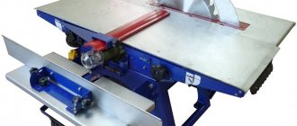
Belt sanding with profile pressing iron
Abrasive tool used
Endless sanding belts on an elastic fabric base with a “B” type butt joint (overlapping with removal of abrasive in the seam area):
- due to the elasticity of the base, the sanding belt precisely bends around the profile being processed;
- The overlapping butt joint of the sanding belt (type “B”) has high resistance to lateral bending of the belt, which is necessary when processing profile surfaces.
Equipment
Pass-through type machines containing from 2 to 10 or more grinding units. A large number of grinding units allows you to completely cover the profile of the part, thereby processing an extremely complex profile, and also use sanding belts of several types of grain sizes when running the part through the machine.
Processed parts
Any molded products, as well as profile edges of solid wood or MDF parts.
Principle of operation
Sanding is performed with a belt on an elastic fabric base, stretched between the shafts and pressed against the surface to be treated using a special profile iron. Depending on the grain size of the sanding belt used, it is possible to carry out both coarse grinding (P-80 - P-150) before applying primer, and delicate grinding grinding the primed surface (R-180 – R-320). Also, the aggressiveness of grinding can be adjusted by increasing or decreasing the operating pressure applied to the pressing pad. To process different profiles, it is possible to use several sets of sanding pads. Most modifications of machines allow for easy and quick replacement of the iron with a new one.
Loose belt sanding
Abrasive tool used
Endless sanding belts on a fabric basis with a butt joint of the “T” type (butt to substrate): - soldering the sanding belt butt to the substrate allows you to obtain an extremely strong connection of the belt with a slight increase in the thickness of the seam, which, when working with a loose belt, does not cause any beating and does not affect the quality of the treated surface.
Equipment
Machines of various types and modifications with automatic or manual supply of workpieces to the grinding zone. The main distinctive feature of this equipment is that the grinding zone is located on a free section of the sanding belt, which does not have any supporting part. Grinding with a free sanding belt is most often found in the metalworking industry.
Processed parts
Curvilinear profile parts: turbine blades, sanitary mixers, fittings, individual elements of furniture fittings and much more.
Principle of operation
The workpiece is fed to the abrasive belt by the operator manually or automatically. The belt is tensioned by rollers or shafts in the working area and is not supported by any devices. The workpiece can be fed onto the abrasive material at various angles and planes.
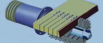
Grinding with profiling wheels
Abrasive tool used
Grinding wheels with different structures and types of base.
Petal – is a circle (shaft) consisting of segments/petals of abrasive material evenly spaced around the circumference. As a material for the petals, abrasive non-woven material can be used in a monogamous design, as well as in combination with abrasive segments on paper and fabric bases. Circles of this type may differ from each other in hardness, which depends on the density, the number of petals located at a certain landing diameter, and the type of special impregnation.
Twisted - is a circle (shaft), the body of which is made of abrasive non-woven material, multi-layered onto the bore diameter. Circles of this type may differ from each other in hardness, which is determined by the initial rigidity of the non-woven material itself, the degree and type of special impregnation, as well as the density of its wrapping, that is, the number of layers/revolutions.
Polyurethane – the basis of these wheels consists of a polyurethane mass in which abrasive grains are distributed evenly throughout the entire volume. Depending on the purpose of the tool, along with abrasive particles, abrasive fibers of non-woven material can be added to the composition of the wheel. Wheels of this type differ from each other in density, porosity, the polyurethane itself and the concentration of abrasive grains. To profile the wheels, an abrasive material on a flexible fabric base is used, which is glued to the profile of the surface being treated using glue in a single strip of 1 m. Profiling is carried out by pressing the profile to the circle at low speeds of rotation of the circle.
Equipment
Through-type machines with automatic feeding of the grinding wheel to the workpiece and compensation for wheel wear, as well as machines with manual pressing of the workpiece to the grinding wheel.
Processed parts
Any molded products, as well as profiled edges of parts.
Principle of operation
The workpiece is fed manually or automatically onto a circle that already has the profile of the workpiece. During the work, the circle gradually wears out, while maintaining the initially specified profile.
To obtain a high-quality surface, as well as to increase the working life of the wheel, it is necessary to strictly adhere to the maximum permissible rotation speeds recommended by the wheel manufacturer
Brush grinding
Abrasive tool used
Various modifications of brush grinding elements: A disc of the “fladder” or “SHAFT Star” type is a multi-beam star made of sanding paper on a fabric basis with plastic spacers that ensure the correct positioning of the discs relative to each other.
“SHAFT Flex” type sanding brushes – the basis of this tool is a central sleeve into which the sanding brushes are inserted. The brushes themselves consist of the following elements:
- base – plastic base for fastening to the central bushing;
- sanding paper – elastic sanding paper, cut into petals;
- bristles - can be made of sisal or fishing line.
End brush element - this type of grinding element consists of brush segments mounted on a disk that carries out rotational movements in the same plane with the surface being processed.
Equipment
Grinding elements of the “fladder” type - “SHAFT Star” or “SHAFT Flex” (see points 1 and 2) can be used both with hand tools and on industrial machines. The end brush element (see point 3) is used only for working on machine tools.
Processed parts
Profile surfaces with a profile depth of up to 20 mm (depending on the type of element used). They are used for fine sanding of wood and interlayer sanding of soils, as well as for rustication (aging of the wood surface). In metalworking it is mainly used to remove rust and coatings from metals.
Principle of operation
Brush grinding elements do not require profiling; penetration into the depth of the processed profile is achieved by dividing them into separate segments (petals of sanding cloth).
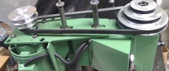
General view of profile grinding machine 395M
Photo of profile grinding machine 395M
Photo of profile grinding machine 395M
Photo of profile grinding machine 395M
How to order and buy a profile grinding machine at Pumori-engineering Invest
If you are interested in purchasing, check out the catalog on the website. The product list is represented by three models: ACC-DXNC, UPZ-NC, UPZ-Li.
Our company’s highly qualified specialists in Yekaterinburg will help you choose the right model. Contact by phone or leave a request by email.
You can also order a profile grinding machine at a price corresponding to the quality through an application on our website.
Pumori-engineering invest has been working with the Japanese manufacturer Okamoto for several years and guarantees accuracy, reliability, and durability. Benefits of purchasing grinding equipment from us:
- Related services: technical audit, operator training, software supply, commissioning, service;
- Leasing programs;
- Operational service;
- Original spare parts from the manufacturer.
Location of controls for profile grinding machine 395M
Location of controls for profile grinding machine 395M
- Grinding head lower turntable clamp handle
- Grinding head middle turntable clamp handle
- Handle for moving the lower support of the grinding head
- Screw for changing the gear ratio of the planetary mechanism (lower support)
Screw in position:
- a) the highest speed of movement of the caliper
- b) the planetary mechanism is turned off, the caliper is moved by handle 3
- c) the lowest speed of movement of the caliper
- Handwheel for manual movement of the upper caliper. For one revolution of the flywheel, the caliper will move 0.02mm
- Handle for tilting the movable glass frame
- Handle for clamping tracing paper together with a movable glass frame
- Flywheel for raising and lowering the product table
- Product Table Lift Column Clamp Handle
- Top light switch
- Bottom light switch
- Network switch
- Handle for longitudinal movement of the product table
- Clamping handle for the lower slide of the product table
- Handle for transverse movement of the product table
- Clamping handle for the upper slide of the product table
- Diamond grinder longitudinal movement screw
- Cross movement screw for diamond cutter
- Toggle switch for changing the direction of movement of the lower support of the grinding head
- Automatic control handle for the lower support of the grinding head
- General switch for upper and lower lights
- Spindle start and stop buttons
- Automatic control handle for the upper support of the grinding head
- Toggle switch for changing the direction of movement of the upper support of the grinding head
- Diamond grinder swing handle
- Clutch shift handle for changing the number of double strokes of the grinding spindle slide
- Spline groove for changing the stroke length of the grinding spindle slide
- The clamping handle of the grinding head after turning it to the back angle
- Hole for rotating the grinding head by the angle of the side edges
- The clamping handle of the grinding head after turning it to a side angle
- Screw for changing the gear ratio of the planetary mechanism (upper caliper)
- a) the highest speed of movement of the caliper
- b) the planetary mechanism is turned off: the caliper is moved by handle 35
- c) the lowest speed of movement of the caliper
Screw in position:
- A. Lower rotation scale of the grinding head
- B. Average rotation scale of the grinding head
- B. Upper rotation scale of the grinding head
- D. Rotation scale for the grinding head to set the lateral angle
- D. Grinding head rotation scale to set the clearance angle
- E. Diamond grinder rotation scale
Operation of profile grinding machine 395M
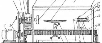
Diagram of the optical device of the 395M profile grinding machine
The 395M profile grinding machine with a screen is shown in Fig. 76, a. The workpiece is fixed on a coordinate table 23, which has longitudinal, transverse and vertical movement from precise lead screws. The longitudinal movement of the slide 18 is carried out by the handle 19, the transverse movement of the slide 20 by the handle 21, the vertical movement of the table by the flywheel 22. The part is installed on the work table 17, which is mounted on the upper longitudinal slide of the coordinate table and, together with the table, is located under the lens 13 of the optical device. The optical system projects an enlarged image of the part profile onto screen 14. The part profile drawing, made on a scale of 50:1, is fixed between two screen glasses and illuminated by illuminators 15 and 16.
The grinding head 24 together with the grinding wheel spindle 8 has installation and working movements. The spindle, mounted in a vertical slide 10, makes a reciprocating movement when the lever 11 is turned on. The stroke length of the slide is 0-50 mm. Using screw 12, the grinding wheel is adjusted in height relative to the profile of the workpiece. The movable flange 4 is used to rotate the circle in the horizontal plane, and the circular slides 6 and 7 are used to install it at an angle in the horizontal and vertical planes. The grinding head is mounted on the upper longitudinal slide 3, which moves along the lower transverse slide 1 using handles 2 and 5. The grinding wheel rotates from an electric motor 9. Periodic dressing of the wheel is carried out using a device mounted on the side wall of the circular slide 10.
The machine allows you to grind various profiles of flat and round parts with an accuracy of 0.01-0.02 mm. Processing is done like this. The worker manually moves the grinding head relative to the profile of the part and ensures that the cutting edge of the grinding wheel always exactly coincides with the corresponding point in the enlarged image of this profile, combined with the profile of the drawing on the screen.
The optical device diagram is shown in Fig. 76, b. A ray of light from lamp 1, passing through lenses 2 and 3, prism 4, diaphragm 5, lenses 6-9, projects the outline of the part on the projector screen 14 in the form of a clear shadow. Illuminators 13 additionally illuminate the part through lenses 10-12. Next, the rays pass through a projection lens consisting of lenses 15, 16, 17 and are directed through a prism 18 to a mirror 19, reflecting from which they fall on a mirror 20 and then onto a screen consisting of glasses 21 and 22 with a drawing fixed between them. An on-screen error of 1 mm corresponds to a workpiece profile error of 0.02 mm.
In addition to the described types of machines that operate with a grinding wheel, there are profile grinding machines that operate with a flexible abrasive belt. In such machines, a moving belt with an abrasive applied to it, fitting the shaped profile of the surface being processed, polishes it.
Internal grinding machines
Application of internal grinding machine.
Internal grinding machines are designed for grinding internal rotating surfaces. The use of an internal grinding machine is one of the progressive methods of metal cutting. Grinding itself means the process of processing workpieces by cutting using tools - wheels consisting of abrasive material. In mechanical engineering, the following types of grinding are most often used:
- round outer,
- round inner
- flat.
An internal grinding machine works on the round inner one. The action is carried out due to the longitudinal feed of the grinding wheel, possibly the workpiece, as well as plunging processing.
The internal grinding machine belongs to the grinding group of machines that are designed for the production of parts with small deviations in shape, size, small surface roughness parameters and are characterized by high productivity.
This type of equipment is used for processing internal rotating surfaces. This type of machine is used for grinding holes.
Internal grinding machine. Description.
Holes in parts on internal grinding machines are processed by passing and plunging. The plunge method is used when processing short, shaped, blind holes that do not have grooves to exit the circle. In all other cases, pass grinding is used, which provides higher accuracy and a lower surface roughness parameter.
The internal grinding machine is equipped with a user-friendly interface. This makes processing of products very simple. Additionally, the machines can be equipped with various measurement and part control systems, which increases productivity.
Properties and characteristics of internal grinding machines.
The internal grinding machine is equipped with a feeding system and a compensation straightening system. They are two independent systems. After changing a new wheel there is no need to adjust the machine. A single processing cycle to control the final size of the workpiece.
The internal grinder is equipped with a jumping device, so there is no need to manually reset after measuring or straightening.
The work table is equipped with an axial micro-motion device in order to process the end surface with an internal grinding spindle. It is driven by hydraulics. Stepless speed control. There is a manual or hydraulic feed of the grinding wheel. The thyristor converter changes the spindle speed. The bed of the internal grinding machine has a machined surface for installing a steady rest to grind long workpieces.
The internal grinding machine is equipped with an end surface grinding application. The rotating speed of the grinding spindle is 18000r/min. The largest internal diameter of the sanded product can reach 20mm.
Internal grinding machine - types.
Internal grinding universal machine 3A228. This machine is used in tool and repair shops with single or small-scale production.
The centerless internal grinding machine model 6S153M is used for grinding mounting holes in the inner rings of ball bearings and similar parts.
The 3K228A internal grinding machine is designed for grinding cylindrical, conical, blind, and through holes. It has a wide range of rotation speeds for grinding wheels, the product spindle, cross feed values and table movement speeds, ensuring the processing of parts at optimal conditions. In this type of internal grinding machine, roller guides for the transverse movement of the grinding head, together with the final link - a ball, screw pair - provide minimal movements with high accuracy.
The 3K228A internal grinding machine has an accelerated adjustment transverse movement of the grinding head. This significantly reduces the auxiliary time during its changeover. Another positive factor of such equipment is the reduction in heating of the frame. Plus, the transfer of vibration to the machine is eliminated. The hydraulic drive on the internal grinding machine is installed separately from the machine and connected to it with a flexible hose. The magnetic separator, as well as the conveyor filter for this machine model, ensure high quality cleaning of the coolant. This improves the quality of the processed surface.
The 3K229A universal internal grinding machine is distinguished by particularly high accuracy GOST 8-82 A. The largest diameter of the grinding wheel is 250x76x63 mm
Kinematic diagram of profile grinding machine 395M
Kinematic diagram of profile grinding machine 395M
The 395M profile grinding machine can grind flat and round surfaces with complex profiles. The size of the sanded plane is 10 X 10 mm. The size of the plane during combined processing using standard tiles is 150 x 60 mm, the maximum thickness of the sanded product is 48 mm.
Several form-building executive movements are created on the machine:
- movement of cutting speed - rotation of the grinding wheel
- reciprocating movement of vertical feed - movement of the slide in the direction of the thickness of the workpiece 1
- profile feed - mutually coordinated movements of the upper 2 and lower slides 3 of the grinding headstock.
The kinematic group of cutting speed movement is simple . Its internal connection consists of one rotational kinematic pair between the grinding wheel spindle and the grinding head 4 mounted on the slide. The external connection is a belt drive between the motor shaft and the wheel spindle. All parameters of this movement are constant and cannot be adjusted. The grinding wheel with a diameter of 125 mm has 3000 rpm.
The kinematic group of movement of the vertical feed of the slider is simple , with an internal connection in the form of one translational kinematic pair between the slider 5 and the body of the grinding headstock.
An external connection transmits movement from the D1 engine through a belt drive to a pulley with a diameter of 110 mm and then through the is1 box and the rocker mechanism to the slider 5. This movement is simple, with an open trajectory and must be adjusted according to four parameters. In fact, the adjustment is made: to the path - by turning the eccentric bushing, which changes the position of the rocker pin, to the speed - by the feed box is1 of the slider (two stages of 45 and 85 stroke/min are possible), to the initial position - by changing the position of connecting the rocker to the slider through the lead screw on the slider; The direction of movement is not adjusted, since grinding occurs in both directions.
The kinematic group of the profile feed is complex , creating a two-element executive movement. Its internal connection, located between the upper slide 2 of the grinding headstock and the lower slide 3, includes not only the gear wheels of the gearboxes, but also the DC motors D2 and D3 and the worker himself, who looks at the screen and controls the rotation speeds of the motors D2 and D through rheostats. D3. Using an optical system, the screen displays a drawing of the workpiece profile, enlarged 50 times (the profile is drawn in dissected form with thin lines 0.2 mm thick), and the actual position of the contours of the wheel and the workpiece during grinding, also enlarged 50 times. The profile drawing of a part on the screen is like a copier, to the contour of which the worker tries to bring the circle closer. This internal connection is not purely mechanical; it also includes a person as an element of a biological connection, and such a connection, apparently, can be called biomechanical. Engines D2 and Dz are also in internal communication and, thus, external communication merges with internal communication. The accuracy of the work of this group mainly depends on the worker himself.
If a worker operates the machine manually with engines D2 and D3 turned off, then he is not only an internal communication element that coordinates the speeds of linear movements P3 and P4, but also a source of movement. The gearboxes of this group have built-in planetary mechanisms with a recessed key that connects the lead screw either directly to the worm wheel (fast movement) or to the left central wheel (slow movement).
Manual, vertical, longitudinal and transverse movements of the table 6 with the part to be ground are auxiliary movements, mainly necessary to obtain the correct image of the part on the screen.
The grinding head can be installed inclined in two planes.
To grind shaped bodies of rotation (round shaped cutters), a special device with its own motor is installed on the table, which allows you to rotate the part being ground (not shown in the figure).
The machine has a device for straightening the wheel.
Since grinding different sections of a part’s profile often requires the use of grinding wheels of different shapes, each wheel has its own flange to quickly change them during operation.
Specifications
Characteristics of machines for grinding internal surfaces:
- diameters of machined holes from 6 to 800 mm;
- engine speed from 12 thousand rpm. up to 80 thousand rpm;
- electric motor power from 1.5 to 11.5 kW;
- grinding head stroke length up to 500 mm;
- workpiece rotation speed from 10 to 2000 rpm;
- grinding speed up to 35 m/s;
- processing accuracy up to 1 micron;
- disc roughness from 0.08 microns.
Technical characteristics of the machine 395M
| Parameter name | 395m | 395mF10 | 3951VF1 |
| Work piece profile size | |||
| Largest dimensions of the sanded product, mm | 150 x 60 x 78 | 150 x 60 x 78 | 150 x 60 x 78 |
| Maximum profile height of the sanded product, mm | 48 | 78 | 78 |
| Size of direct grinding plane at x50 magnification, mm | 10 x 10 | 10 x 10 | 10 x 10 |
| Direct grinding plane size at x25 magnification, mm | 20 x 20 | 20 x 20 | 20 x 20 |
| Direct grinding plane size at x25 magnification, mm | 50 x 50 | ||
| Grinding plane size using reference tiles, mm | 150 x 60 | ||
| Maximum thickness of the workpiece, mm | 48 | ||
| Basic movements of the grinding head supports | |||
| Rotation of the lower caliper, degrees | ±45° | ±45° | ±45° |
| Movement of the lower support in the transverse direction, mm | 150 | 150 | 160 |
| Rotation of the upper caliper, degrees | ±45° | ±45° | ±45° |
| Movement of the upper support in the longitudinal direction, mm | 130 | 200 | |
| Speed of movement of the grinding head supports, mm/min | 0,2..1,0; 4..20 | ||
| Rotation of the grinding head head around a horizontal axis, deg | ±10° | ±15° | |
| Rotation of the grinding spindle slide around the horizontal axis, deg | +10°..-30° | +5°..-30° | +5°..-30° |
| Stroke length of the grinding slide, mm | 50 | 6..80 | 6..80 |
| Number of double strokes of the grinding slide, stroke/min | 45; 85 | 44; 88 | 44; 88 |
| Basic movements of the product table | |||
| Vertical movement of the table together with the column, mm | 100 | 100 | 100 |
| Longitudinal movement, mm | 60 | 60 | 60 |
| Transverse movement, mm | 150 | 150 | 150 |
| Maximum grinding wheel diameter, mm | 125 | 150 | 150 |
| Rotation speed, rpm | 3500 | 3700; 4500 | 3600; 4500 |
| Magnification of the optical system | 25:1, 50:1 | 25:1, 50:1 | 10:1; 25:1, 50:1 |
| Working area of the screen, mm | 500 x 500 | 500 x 500 | 500 x 500 |
| Optical projector type | IZP-25 | IZP-25 | IZP-25 |
| Drive and electrical equipment of the machine | |||
| Type of digital display device | — | F5291 | F5291 |
| Number of electric motors on the machine | 4 | 9 | |
| Spindle motor, kW | 0,65 | 0,55 | |
| Electric motor for driving the grinding head supports, kW | 0.1 x 2 | 0.12 x 2 | |
| Electric motor for moving the grinding spindle carriage, kW | 0,25/ 075 | ||
| Electric motor of the cylindrical grinding device, kW | 0,12 | ||
| Vacuum cleaner electric motor, kW | 0,65 | 0,75 | |
| Cooling pump electric motor, kW | 0,01 | ||
| Bottom lighting fan, kW | 0,028 | ||
| Total power of electric motors, kW | 2,35 | 2,5 | |
| Overall dimensions and weight of the machine | |||
| Overall dimensions of the machine (length x width x height), mm | 1485 x 1600 x 2000 | 1555 x 1620 x 2000 | 1955 x 1650 x 1960 |
| Weight of the machine with electrical equipment and cooling, kg | 1500 | 1965 | 2400 |
- Optical profile grinding machine 395-m. Passport and manual, 1963
- Alperovich T.A., Konstantinov K.N., Shapiro A.Ya. Design of grinding machines, 1989
- Alperovich T.A., Konstantinov K.N., Shapiro A.Ya. Setup and operation of grinding machines, 1989
- Dibner L.G., Tsofin E.E. Sharpening machines and semi-automatic machines, 1978
- Genis B.M., Doctor L.Sh., Tergan V.S. Grinding on cylindrical grinding machines, 1965
- Kashchuk V.A., Vereshchagin A.B. Grinder's Handbook, 1988
- Kulikov S.I. Honing, 1973
- Lisova A.I. Design, adjustment and operation of metal-cutting machines, 1971
- Loskutov V.V. Grinding machines, 1988
- Lurie G.B. Grinding machines and their adjustment, 1972
- Lurie G.B. Design of grinding machines, 1983
- Menitsky I.D. Universal sharpening machines, 1968
- Mutsyanko V.I. Bratchikov A.Ya. Centerless grinding, 1986
- Naerman M.S., Naerman Ya.M. Guide for training grinders. Textbook for vocational schools, 1989
- Naerman E.S. The Young Grinder's Handbook, 1991.
- Popov S.A. Grinding work, 1987
- Tergan V.S. Grinding on cylindrical grinding machines, 1972
- Shamov B.P. Types and designs of main components of grinding machines, 1965
Bibliography:
Related Links. Additional Information
- Classification and main characteristics of the grinding group
- Repair, restoration and modernization of grinding machines: the American approach
- Cylindrical grinding. Processing on cylindrical grinding machines. Grinding Methods
- Setting up a cylindrical grinding machine when installing parts in centers
- CNC grinding machines
- Marking of grinding wheels
- Testing and checking metal-cutting machines for accuracy
- Grinding machines. Market of grinding machines in Russia
- Manufacturers of grinding machines
- Directory of grinding machines
Home About the company News Articles Price list Contacts Reference information Interesting video KPO woodworking machines Manufacturers
Features and purpose of profile grinding machines for metal.
High-precision CNC profile grinding machines are used in complex grinding of workpiece surfaces with a curved generatrix in automatic mode.
The power for profile processing is equipped with modern CNC and additional grinding control devices.
The interaction of equipment elements is ensured by an innovative control system based on Fanuc software.
By choosing Okamoto CNC metal profile grinding machines as your working machines, you get standard high-precision grinding equipment with a lot of advantages:
- Own components;
- Accurate to 0.6 microns;
- High processing speed;
- “Multi-profile” grinding machines: application in many industries;
- Simple CNC system (simultaneous control of two coordinates).