Hello! There are many people on this resource who work in electronics and make their own printed circuit boards. And each of them will say that drilling printed circuit boards is a pain. Small holes have to be drilled in hundreds and everyone solves this problem for themselves. In this article, I would like to present to your attention an open-source project for a drilling machine that anyone can assemble themselves and will not need to look for CD drives or object tables for a microscope.
Description of design
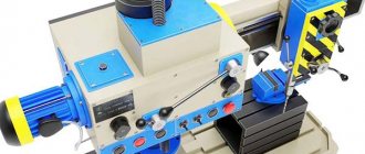
The design is based on a fairly powerful 12-volt motor from China.
Included with the engine, they also sell a cartridge, a wrench and a dozen drills of different diameters. Most hams simply buy these motors and drill the boards while holding the tool in their hands. I decided to go further and, based on it, make a full-fledged machine for similar engines with open drawings for independent production.
To move the motor linearly, I decided to use 8mm diameter polished shafts and linear bearings. This makes it possible to minimize backlash in the most critical place. These rollers can be found in old printers or purchased. Linear bearings are also widely used and available in 3D printers.
The main frame is made of 5mm thick plywood. I chose plywood because it is very cheap. Both the material and the cutting itself. On the other hand, nothing prevents (if possible) from simply cutting out all the same parts from steel or plexiglass. Some small parts with complex shapes are 3D printed.
To lift the engine to its original position, two ordinary rubber bands were used. In the upper position, the motor switches itself off using a microswitch.
On the reverse side I provided a place to store the key and a small case for drills. The grooves in it have different depths, which makes it convenient to store drills with different diameters.
But it’s easier to see all this once on video:
There is a slight inaccuracy on it. At that moment I came across a defective engine. In fact, from 12V they consume 0.2-0.3A at idle, and not two, as they say in the video.
General information about drilling machines
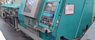
Any drilling machine is necessary to provide the ability to effectively process parts made from various materials. Where high precision processing is required (as is known, this does not apply to the process of drilling holes), manual work must be eliminated as much as possible from the technological process. Such problems cannot be solved by any drilling machine, including homemade ones. It is practically impossible to do without machine equipment when processing hard materials, for drilling holes where the efforts of the operator himself may not be enough.
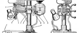
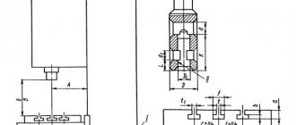
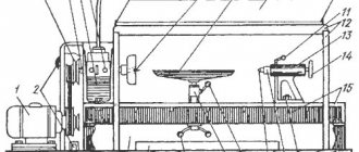
Design of Bench Drilling Machine with Belt Drive (Click to Enlarge)
Any machine for drilling is a structure assembled from many components that are not reliably fixed relative to each other on the supporting element. Some of these nodes are rigidly fixed to the supporting structure, and some of course cannot move in one or more spatial positions.
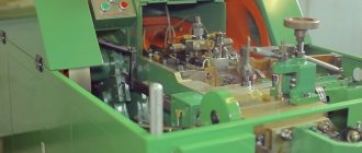
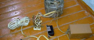
An example of motors used in the manufacturing process of a homemade mini drilling machine
The basic functions of any drilling machine, the use of which does not ensure the processing process, is the rotation and movement in the vertical direction of the cutting tool - the drill. In numerous modern models of such machines, the working head with the cutting tool can move not in a horizontal plane, which allows this equipment to be used for drilling several holes without moving the part. Today, a set of accounting automation programs is being actively introduced into modern drilling machines, which significantly increases their productivity without increasing the accuracy of processing.
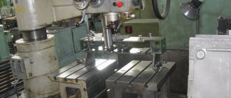
Below, for example, are presented several design options for homemade drilling machines for circuit boards . Any of these diagrams can serve as a model for your machine.
Parts for assembly
- Engine with chuck and collet. On the one hand, a jaw chuck is very convenient, but on the other hand, it is much more massive than a collet clamp, that is, it is often subject to beats and very often they have to be additionally balanced.
- Plywood parts. A link to files for laser cutting in dwg format (prepared in NanoCAD) can be downloaded at the end of the article. You just need to find a company that deals with laser cutting of materials and give them the downloaded file. I would like to note separately that the thickness of the plywood may vary from case to case. I come across sheets that are a little thinner than 5mm, so I made the grooves 4.8mm each.
- 3D printed parts. A link to files for printing parts in stl format can also be found at the end of the article
- Polished shafts with a diameter of 8mm and a length of 75mm - 2 pcs. Here is a link to the seller with the lowest price for 1m that I saw
- Linear bearings 8mm LM8UU - 2 pcs.
- Microswitch KMSW-14
- Screw M2x16 - 2 pcs.
- Screw M3x40 h/w – 5 pcs.
- Screw M3x35 slot - 1 pc.
- Screw M3x30 h/w – 8 pcs.
- Screw M3x30 h/w with countersunk head - 1 pc.
- Screw M3x20 h/w - 2 pcs.
- Screw M3x14 h/w - 11pcs
- Screw M4x60 slot - 1 pc.
- Bolt M8x80 - 1 piece
- Nut M2 - 2 pcs.
- M3 square nut – 11pcs
- Nut M3 – 13pcs
- M3 nut with nylon ring - 1 pc.
- Nut M4 - 2 pcs.
- M4 square nut – 1 piece
- M8 nut – 1 piece
- Washer M2 - 4 pcs
- Washer M3 – 10pcs
- M3 washer enlarged - 26 pcs.
- M3 locking washer – 17 pcs.
- M4 washer - 2 pcs.
- M8 washer - 2 pcs.
- M8 locking washer – 1 piece
- Set of installation wires
- Heat shrink tube set
- Clamps 2.5 x 50mm - 6 pcs
Assembly
The whole process is shown in detail in the video:
If you follow exactly this sequence of actions, then assembling the machine will be very simple.
This is what a complete set of all components for assembly looks like
In addition to them, assembly will require a simple hand tool. Screwdrivers, hex keys, pliers, wire cutters, etc.
Before starting to assemble the machine, it is advisable to process the printed parts. Remove possible sagging, supports, and also go through all holes with a drill of the appropriate diameter. Plywood parts along the cut line may become stained with smoke. They can also be sanded with sandpaper.
Once all the parts are prepared, it's easier to start by installing the linear bearings. They creep inside the printed parts and are screwed to the side walls:
Next, the handle with gear is installed. The shaft is inserted into a large hole, the base of the handle is installed on it and the whole thing is tightened with an 8mm bolt. The handle itself is an M4 screw:
Now you can assemble the plywood base. First, the side walls are installed on the base, and then the vertical wall is inserted. There is also an additional printed piece at the top that defines the width at the top. When driving screws into plywood, do not use too much force.
It is necessary to make a countersink in the table on the front hole so that the head screw does not interfere with drilling the board. A printed fastener is also installed at the end.
Now you can begin assembling the engine block. It is pressed with two parts and four screws to the movable base. When installing it, you must ensure that the ventilation holes remain open. It is secured to the base using clamps. First, the shaft is threaded into the bearing, and then clamps are snapped onto it. Also install an M3x35 screw, which in the future will press the microswitch.
The microswitch is installed on the slot with a button towards the engine. Its position can be calibrated later.
The rubber bands are placed on the bottom of the engine and threaded through to the “horns”. Their tension must be adjusted so that the engine rises to the very end.
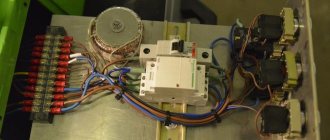
Now you can solder all the wires. There are holes on the engine block and next to the microswitch for clamps to secure the wire. This wire can also be routed inside the machine and brought out from the back. Make sure you solder the wires on the microswitch to the normally closed contacts.
All that remains is to install the pencil case for the drills. The top cover must be clamped firmly, and the bottom cover must be tightened very loosely, using a nut with a nylon insert for this.
This completes the assembly!
Add-ons
Other people who have already assembled such a machine made many suggestions. If you allow me, I will list the main ones, leaving them in their original form:
- By the way, it would be good to remind those who have never worked with such parts before that plastic from 3D printers is afraid of heat. Therefore, you should be careful here - you should not go through holes in such parts with a high-speed drill or Dremel. Handles, hands...
- I would also recommend installing the microswitch at a very early stage of assembly, since you still need to be able to screw it to an already assembled frame - there is very little free space. It would also not hurt to advise craftsmen to at least tin the microswitch contacts in advance (or even better, solder the wires to them in advance and protect the soldering points with pieces of heat-shrink tubing), so that later during soldering they do not damage the plywood parts of the product.
- Apparently I was lucky and the chuck on the shaft was not centered, which led to serious vibration and hum of the entire machine. I managed to fix it, but it's not a good option. Since the rotor axis bends, and it is no longer possible to remove the cartridge, there are fears that I will pull out this very axis entirely.
- Tighten the screws with locking washers as follows. Tighten the screw until the lock washer closes (straightens). After this, turn the screwdriver 90 degrees and stop.
- Many people advise attaching a speed regulator to it according to Savov’s scheme. It turns the engine slowly when there is no load, and increases speed when load appears.
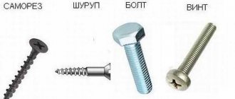
Tags: mini drill, for printed circuit boards, homemade, electronic crafts
Comments 33
Honestly? This is perversion, there is no need to advise people to collect such nonsense. And even more so, there is no need to drill PP with a hand drill. Unless accuracy is not important to you and you have a free car with drills.
This is what I have. I've been using it for a year.
Good hardened drill bits can be easily broken with this type of drill. I have a similar one made, it can only be drilled well with cheap drills, and they don’t last long. I’m still planning to design it in the form of a machine, but I still can’t get it together)
Damn I just recently threw out the photo enlarge it Damn - it was lying in the closet for about 30 years...damn
I didn’t have one, I asked my friends and they gave me an unnecessary one. And I looked at Avito - there were only optimists gathered there