Information about the manufacturer of the surface grinding machine 3D756
The manufacturer of the 3D756 surface grinding machine is the Voronezh Machine Tool Plant , founded in 1960.
The developer of the machine model 3D756 is Odessa Special Design Moscow Bureau of Special Machine Tools (SKBSS) 1973.
Machine tools produced by the Voronezh Machine Tool Plant
- 3A228
- internal grinding machine Ø 400 - 3B724
surface grinding machine with horizontal spindle 400 x 2000 - 3D725
- surface grinding machine with a horizontal spindle 630 x 2000 - 3D756
- surface grinding machine with a vertical spindle Ø 800 - 3E756
- surface grinding machine with a vertical spindle Ø 800 - 3K228A
- universal internal grinding machine of especially high precision Ø 400 - 3K228V
– high-precision universal internal grinding machine Ø 400 - 3K229A
- universal internal grinding machine of especially high precision Ø 800 - 65A60F1
- vertical milling machine without console with digital display 630 x 2000
3D756 List of components of a surface grinding machine
- Bed 3D756.101
- Column 3D756.111
- Motion drive steel 3D756.211
- Table movement reducer 3D756.212
- Table rotation drive 3D756.213
- Gearbox 3D756.214
- Table carriage 3D756.221
- Grinding head 3D756.301
- Rolling screw-nut transmission 3D756.303
- Feed mechanism 3D756.331
- Feed reducer 3D756.333
- Accessories 3D756.451
- Segment head 3D756.511
- Pneumatic communication 3D756.541
- Lubrication system 3D756.601
- Lubrication unit 3D756.611
- Cooling system 3D756.652
- Pistol 3D756.653
- Cooling unit 3D756.661
- Electrical equipment of the machine 3D756.801
- Electrical equipment of cooling unit 3D756.811
- Control panel 3D756.821
- Electrical equipment pipeline 3D756.875
- Electrical equipment of cabinet 3D756.841
- Stove control unit 3D756.845
- Electromagnetic plate 3D756.862
- Electrical cabinet 3D756.873
- Grinding wheel housing 3D756.901
- Protective cover for bed guides 3D756.911
- Protective casing for column guides (lower) 3D756.922
- Table fencing 3D756.932
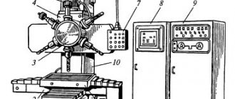
3D756 Location of surface grinding machine controls
Location of machine controls 3D756
- Signal light "Network"
- Signal lamp “Inlet and outlet of grinding wheel”
- Grinding head retract time delay regulator
- Machine light switch
- All stop button
- Feed Push Button
- Feed type switching handle
- Dosing handle
- Lubrication Start Button
- Button “Tap by time relay”
- “Accelerated headstock retraction” button
- Table rotation speed switch handles
- Flywheel for manual movement of the grinding headstock
- Table jog button
- Table Right button
- Signal light “Plate magnetization”
- Plate magnetization button
- Switch “Stove on/off”
- Button “Stop table movement”
- Plate demagnetization button
- Signal lamp "Demagnetization of the plate"
- Table Left button
- Table Rotation button
- Button “Slow approach of headstock”
- Button "Accelerated approach of the headstock"
- Button "Start working feed"
- Feed stop button
- Cooling start button
- Stop cooling button
- Grinding wheel guard position handle
- Button “Start circle rotation”
- Operating mode selection switch
- Straightening mechanism handle
- Processing time delay controller
- Feed speed regulator
- Grinding head feed rate indicator
- Grinding wheel motor load indicator
- Visual inspection device
Description of the kinematic diagram of the 3D756 surface grinding machine
The 3D756 machine has the following separated kinematic chains:
- Grinding wheel rotation
- Table rotation
- Moving the table carriage along the bed
- Vertical feed of the grinding head
1. The rotation of the grinding wheel is carried out from the built-in electric motor 51 (N = 30 kW, n = 980 rpm).
2. The rotation of the electromagnetic table is carried out from electric motor 1 (N = 2.2 kW, n = 1420 rpm) through a V-belt transmission, a six-speed gearbox, 16-17 bevel and 18-19 cylindrical pairs of gears.
3. The table carriage moves from an electric motor 20 N = 1.5 kW, n = 920 rpm through a V-belt drive, a worm gearbox, a rack and pinion gear 26 and a rack 27.
4. The grinding head is supplied from a DC electric motor 28 N = 1.5 kW, n = 30-3000 rpm, driven by a magnetic amplifier with a speed control range of 1:100.
The feed mechanism ensures the following types of feeds:
- a) automatic feeding is carried out from the electric motor 28 through a worm gear 29-30, a cylindrical pair 31-32, a worm pair 33-34, a spur gear 35-36 of the feed mechanism and through a worm gearbox 43-44 feeding a screw pair 45 in increments of 10 mm;
- b) accelerated and slow input, and such accelerated output is carried out from the electric motor 28 through two gear sets 37-38, 39-36 to the feed reducer and screw pair 45;
- c) manual movement and manual feed are carried out by rotating the flywheel through a gear pair 41-40;
- d) dosed feed is carried out from a special handle with a pawl and a ratchet wheel 42.
Types of equipment
Surface grinding machines are distinguished by size:
- Tabletop. Small-sized installations are used for processing small parts with relatively low accuracy. They are characterized by economical energy consumption.
- Floor-standing. In the machine parks of large enterprises you can still find Soviet-made machines. They were produced at the Lipetsk Machine Tool Plant in accordance with the requirements of GOST 2789-73. The operation of such equipment is difficult due to the lack of spare parts on the market, the production of which was discontinued in the early 90s. Modern precision surface grinding machines are characterized by high productivity with smaller dimensions.
An important factor influencing the method of influence is the location of the spindle, which can be placed in both vertical and horizontal positions.
Leading manufacturers offer users the following modifications of machines:
- With cross tables. Widely used in tool production. Some models with a fixed column are equipped with guides to move the table in the longitudinal and transverse planes.
- With round tables. Designed for processing round-shaped products. The rotation of the plane is driven by an electric motor.
- Portal. An efficient design that allows the table to move longitudinally to process parts with high precision. The machines have impressive dimensions and high drive power, which makes it possible to perform heavy grinding of products. The working tool is capable of moving in the transverse and vertical planes.
- Console. High-tech equipment, distinguished by methods of moving individual units. The table moves using a hydraulic drive, and a traverse driven by servo drives is responsible for the transverse direction.
There are many types of surface grinding machines on the market, both manual and semi-automatic, with programmable controllers that provide high precision and quality grinding.
Cylindrical grinding machine
The machines of the cylindrical grinding subgroup (Fig. 1) are designed to perform grinding operations on the external and internal surfaces of rotating bodies.
Figure 1. Cylindrical grinding machine.
Structurally, a cylindrical grinding machine consists of a frame (1), a table (2), two headstocks (3.5), in which a cylindrical or conical part is secured, and a drive headstock (4), in which the working element is secured. The working part of this machine is the grinding wheel. There are differences in the way the rotational motion is applied, which are often combined depending on the desired effect:
- the workpiece itself rotates;
- the grinding wheel rotates;
- Both the workpiece and the circle rotate.
In general, the workpiece is fixed in the centers. The grinding wheel drive motor starts. The wheel rotation speed and feed speed are selected. The circle is fed to the workpiece. Longitudinal feed is carried out at a certain speed. During operation, the grinding wheel removes metal from the surface of the workpiece, thereby smoothing out irregularities and reducing roughness.
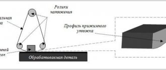
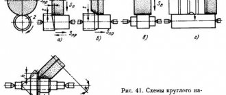
The methods of feeding the grinding wheel when processing a part also differ (Fig. 2).
Figure 2. Grinding methods.
The main methods of grinding the surfaces of bodies of revolution are as follows:
- with longitudinal feed;
- with recess;
- with cutting-in;
- with sequential insertion;
- combined.
Cylindrical grinding machines are divided into the following categories:
- standard;
- specialized;
- universal;
- centerless;
- mortise
The most common is the standard cylindrical grinder.
Internal grinding machine
Internal grinding machines (Fig. 3) are designed for processing internal cylindrical, conical and spherical surfaces.
Figure 3. Internal grinding machine.
Don't miss: Flexible shaft for an engraver, drill or screwdriver: design and purpose
The internal grinding procedure is intended for the final processing of the internal surfaces of parts. One of the positive effects, in addition to removing irregularities and reducing roughness, is the correction of the deviation of the inner surface of the part from the axis of rotation. Such a deviation appears, as a rule, due to errors during previous metal-cutting operations.
The surface grinding machine has two headstocks. One of them has a cartridge installed. The part is secured in the chuck. The second headstock has its own drive. It contains a holder in which the grinding tool is fixed. The headstock is stationary. Feeding is carried out by moving the tailstock on a slide. Often such machines are equipped with an additional supply of lubricating and cooling fluid.
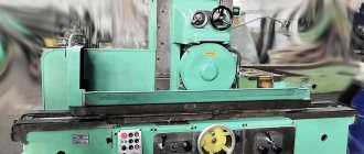
Surface grinding machine
Surface grinding machines (Fig. 4) are designed for processing flat surfaces of parts using an abrasive tool, usually a grinding wheel.
Figure 4. Surface grinding machine.
Structurally, a surface grinding machine consists of a frame on which a table is mounted. The workpiece is fixed in it. A support is installed on the frame. Depending on the degree of mobility of the elements, surface grinding machines are divided into three subgroups:
- with a movable table;
- with movable support;
- with movable table and support.
The support has a grinding head in which the abrasive wheel is fixed. The circle is driven by an electric motor. To change the rotation speed there is a gearbox.
Grinding is carried out by reciprocating movements of the workpiece relative to the abrasive wheel or with a constant feed in one direction until the pass is completed.
Centerless grinding machine
This type is a type of cylindrical grinding machine. A centerless grinding machine (Fig. 5) is used to process parts that cannot be secured at centers. This is due either to the inability to capture the part with the chuck, or to the dimensions.
Figure 5. Centerless grinding machine.
A centerless grinding machine has two grinding wheels, each of which is driven by its own electric motor. One of the circles, as a rule, is fixed statically or has a position adjustment only in height. The second circle is movable and can move over wider ranges. At the bottom there is a so-called support knife, which serves to support the workpiece.
There are three main grinding operations on this machine.
- Longitudinal grinding. Parts with smooth surfaces of various lengths and diameters are subjected to this operation. Feeding occurs when one of the abrasive wheels is rotated or when the position of the support knife changes.
- Plunge grinding. Plunge grinding is used to process parts with conical and spherical surfaces, multi-stage shafts and other parts with a shaped surface.
- Sanding until stop. It is used as an intermediate operation between longitudinal and plunge grinding. In this way, parts that are too long or have a surface shape that is not suitable for other types of grinding are processed. When the grinding wheel reaches its extreme point, the part is removed from the processing area and reinstalled.
Honing machine
Honing machines (Fig. 6) are used to process the external and internal surfaces of parts that have a cylindrical or conical shape. To carry out the grinding operation on this machine, a special honing head is used.
Figure 6. Honing machine.
During operation, the spindle of a honing machine simultaneously performs reciprocating and rotational movements. In this case, a kind of microrelief is applied to the surface of the workpiece.
The honing operation is most widely used in the automotive industry. The inner surface of internal combustion engine cylinders is ground in exactly this way. After honing, microgrooves are formed on the surface of the cylinders, which retain oil, which increases engine life.
Design of surface grinding machine 3D756
bed
The machine bed is a rigid ribbed casting of a closed shape.
The flat and “V”-shaped guides along which the carriage with the table moves are protected from the ingress of coolant and are completely covered by covers.
To limit the movement of the carriage, stops are installed on the horizontal plane of the frame - spring-loaded in the extreme right position and rigid in the extreme left position. The cooling emulsion is collected in the base trough and drains through inclined drains through an outlet into a magnetic separator located on the coolant unit.
The table rotation drive is placed in the right isolated niche of the frame, and the table movement drive is placed in the left niche.
A gearbox is mounted on the front wall of the frame, and a table movement gearbox is placed between the guides.
On the upper right part of the frame, the column tilts at three points.
Special holes are provided for transporting the frame.
The carriage guides are lubricated by special rollers located in the pockets of the frame.
Column
The column is a box-shaped casting with internal stiffeners. The column has rectangular vertical sliding guides for moving the grinding headstock.
The column is installed on a frame on three adjustable supports. Two of them are located on the side of the guides and one on the opposite side - in the middle. All three supports are manually adjustable.
When adjusting, there should be a gap of 1-2 mm between the frame and the column. Three-point adjustment allows you to set the working plane of the grinding wheel strictly parallel to the plane of the electromagnetic table.
A worm feed gearbox with a screw for moving the grinding headstock is mounted between the column guides.
The feed mechanism and the feed mechanism drive motor are built into the column.
The guide columns in the lower part are protected from abrasive dust and coolant by special shields.
Table movement drive
The table movement drive is placed in the left niche of the frame. It consists of an electric motor; slabs; slab base; pulley and V-belt transmission, which transmits rotation from the electric motor to the table movement gearbox. A friction clutch is mounted on the electric motor shaft, connected to a pulley, adjusted to transmit a torque of 145 kgcm.
The plate with the electric motor installed on it intersects along the base guides, providing the necessary tension on the belts.
Table movement reducer
The table movement reducer is installed on the upper plane of the frame between the guides and transmits rotation from the table movement drive through a worm gear and rack and pinion gear to the table carriage rack, with the help of which the table moves along the frame guides from the loading position to the working position. The gearbox is lubricated centrally.
Table rotation drive
The table rotation drive is placed in the right niche of the frame. It consists of the following nodes:
- electric motor;
- plate;
- slab base;
- pulley;
- V-belt transmission that transmits rotation from the electric motor to the gearbox.
The plate with the electric motor installed on it will move along the guides of the base, providing the necessary tension on the belts.
Gearbox of surface grinding machine 3D756
Gearbox of surface grinding machine 3D756
A six-speed, four-shaft 3, 4, 5 gearbox serves to transmit rotation from the electric motor to the table and is installed on the front wall of the frame. All gearbox shafts are assembled on ball bearings. Triple and double gear blocks b and 2 move along the first and third spline shafts, respectively, the position of which is changed by two control handles and provides six different table rotation speeds.
The rolling bearings and gears of the gearbox are lubricated from a centralized system.
Table carriage
The carriage is used to move along the guides of the electromagnetic table frame from the loading zone to the processing zone.
Table carriage 2 is a rigid cast part, ribbed from the inside, with two guides for moving along the frame and a ring guide for rotating the table. An axis 6 is based in the central bore of the carriage, about which the table 3 rotates. A gearbox 10 is attached to the bottom of the carriage, in the bore of which a shaft 8 with a gear 9 is mounted, which rotates the table 3.
A rail I for the longitudinal movement of the carriage is attached to the bottom plane of the carriage.
To protect the frame guides, shields are attached to the ends of the carriage and on its sides, covering the guides in any position of the carriage.
Table 3 - casting with stiffening ribs - has an annular sliding guide II. An electromagnetic plate 5 is attached to the top processed surface of the table. The central bore of the table serves as the base for the radial bearing 7, which, in turn, is based on the axis 6 of the carriage by the inner ring. The rotation of the table is carried out by a helical pair of gears 9, 4.
Lubrication of the friction and gear surfaces is carried out from the crankcase in the table carriage.
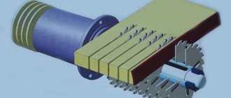
Grinding head
The grinding headstock moves along the vertical rectangular guides of the column from a screw working in tandem with a ball nut fixed in the headstock body.
The grinding headstock is kept from tipping over by bars screwed along the entire length of the guides of the headstock body. The gap between the column and headstock guides is selected using adjusting wedges.
The spindle I of the grinding head rotates in rolling bearings. The lower 6 and upper 3 supports are equipped with double angular contact ball bearings that absorb radial loads. Axial forces on the spindle are perceived by a thrust ball bearing 8 located in front of the lower support, installed with preload. The tension is carried out by calibrated compression springs 7 installed in the housing at the lower spindle support. The magnitude of the tension force exceeds the force created by the weight of the spindle with all the parts mounted on it.
The spindle rotates from a built-in electric motor, the rotor 4 of which is pressed onto the spindle, and the stator is mounted in the headstock housing. To cool the electric motor, a fan 2 is attached to the upper end of the spindle.
The spindle supports are lubricated by supplying grease through grease fittings.
A disk 5 is put on the conical neck of the lower end of the spindle, to which a head with an annular grinding wheel or a segment head is attached with screws. The spindle with the rotor and all the parts assembled on it are subjected to dynamic balancing. The disc with the annular grinding wheel and the segment head are balanced separately. The imbalance should not exceed 10 g.cm and is eliminated by moving the crackers 9 along the grooves of the disks.
A device for dressing the grinding wheel is mounted in the body of the grinding headstock. The straightening mechanism consists of a shaft and a lever mounted at its lower end with a holder in which the straightening tool is fixed - a roller cutter or a diamond pencil. The supply of a roller cutter or diamond to the amount of the abrasive layer to be removed is carried out along the vernier.
Straightening is done by manually rocking the roller of the straightening device. In this case, the editing tool describes an arc, slightly larger in size than the width of the circle. In the non-working position, the roller and lever are kept from free rotation by a spring lock.
A mechanism for lifting the grinding wheel casing is mounted in the headstock body.
The guides and screw pair are lubricated with anti-jump grease from a lubricator mounted on the headstock body, driven by an RD-09 electric motor, N = 10 W; n output shaft = 30.7 rpm
Feed mechanism
The feed mechanism is used for:
- accelerated movement of the grinding head up and down;
- slow supply of the grinding head to the workpiece being sanded;
- mechanical working feed;
- removal of the grinding head from the workpiece being sanded at a speed of 1.5 mm/min.
All these movements are carried out by a DC electric motor 6 driven by a magnetic amplifier.
In addition to the above movements, the feed mechanism carries out:
- manual movement of the grinding head up and down using handwheel I and manual precise feeds when grinding along the limb;
- jog dosed feed.
Adjustment to the depth of the allowance to be removed with automatic shutdown of the working feed is carried out using a time relay.
The feed speed is adjusted using speed regulators installed on the control panel.
The feed mechanism is installed in a niche on the front wall of the column and is covered from the outside with a casing.
During accelerated and slow movements of the grinding head, rotation from the electric motor 6 to the worm shaft I of the feed reducer (Fig. 9) is transmitted through two pairs of spur gears 9, 10, 8, 5 (see Fig. 8).
From the position corresponding to accelerated movement, the movable block can be set to the manual and dosed feed position. During this rotation, flywheel I through a gear pair 2, 3 is transmitted to the worm shaft of the feed reducer. When the block is moved to a position corresponding to automatic feed, rotation is transmitted through a worm pair 12, 11, a gear pair 16, 15, a worm pair 13, 14 and a gear pair 7, 5.
The manual feed gears remain engaged and the flywheel rotates. Rapid traverse and automatic feed can only be activated if the cam located on the axis of the moving block shift handle presses the corresponding limit switch. The switching handle is fixed with a latch in three positions, corresponding to accelerated, manual movement (including dosed feed) and automatic feed.
A pusher is built into the shift handle, which interacts with the button for turning on the electric motor for supplying minimum speed (30 rpm).
When automatic feed is turned on, the handle is immediately placed in a fixed position. If the tooth does not coincide with the cavity of the engaged gear pair 5, 7, gear 5, under the action of spring 4, engages with the rotating gear 7.
Metered feed is carried out by pressing the handle down, while the pawl on the handle turns the ratchet wheel by one tooth. The pawl rotation unit is adjusted using a screw on the front wall of the housing. The ratchet is braked by three brake pads on the flywheel shaft. Lubrication of the feed mechanism is centralized.
Feed reducer
The feed reducer is installed on the column and transmits rotation from the feed mechanism to the lead screw of the grinding headstock.
The gearbox consists of a 3, 2 worm gear with a gear ratio of 1:20. The gearbox shafts are mounted on rolling bearings. Lubrication is centralized.
Comparison
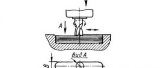
Depending on the position of the spindle, grinding can occur either with the plane (end) of the wheel or with the periphery.
When working with the entire plane, in addition to increased wear of the distal part of the circle, difficulties arise with chip removal. Particles cut off by the central part of the abrasive cannot immediately leave the grinding site. Rolling between the circle and the surface, they leave deep scratches on the metal. To improve the results, the disk of the surface grinding machine can be fixed with eccentricity, or the part can be ground in several passes, gradually shifting the center of the working attachment.
Don't miss: The best 125 mm angle grinders with speed control and soft start for home
When working on the periphery of a circle, there are no problems with chip removal, but another feature arises: processing a large area is possible only in several passes. During operation, the circle wears out and its diameter decreases. It is important to take this reduction into account when re-setting the feed depth every few passes.
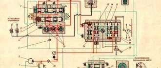
3D756 Pneumatic diagram of a surface grinding machine
Pneumatic diagram of surface grinding machine 3D756
List of elements of the pneumatic circuit
- Measuring device lever
- Command apparatus
- Inlet nozzle
- Stabilizer
- Filter and stabilizer unit
- Water separator
- Pressure switch
- Readout-command pneumatic device
- ..17. Communication lines
Description of the pneumatic system operation
Air from the network at a pressure of 3.5...6 kgf/cm2 (50...92 lb/in2) enters through the moisture separator 6 to the stabilizers 4.5. The measuring system of the device is powered through stabilizer 5, and the arrester of the device through stabilizer 4. Using stabilizer 5, the operating pressure is set to 1...1.5 kgf/cm2 (14...21 lb/in2) when setting up the reading device. Using stabilizer 4, the pressure is set to 1.0 kgf/cm2 (14 lb/in)
Pressure switch 7 is adjusted to a pressure of 3.5 kgf/cm2 (50 lb/in) and when the pressure in the network drops below the set level, it issues a control command to the machine.
The measuring device of the device is located above the machine table, and lever I is in contact with the surface of the workpiece. The measuring arm is kept from moving during the testing process using a special friction brake. Periodically, the control device 2 turns on the arrester, and the brake releases the lever for a short time. Lever I, under the action of a spring, is lowered onto the part or into the space between the parts. The motor of the command apparatus rotates at a constant speed and for each revolution releases lever I for a short time and then connects the measuring nozzle with the reading device 8.
The semiautomatic executive body sends commands to change processing modes using an electronic relay.
Note. A detailed description of the operation of the active (visual) monitoring device is given in the device passport.
Purpose and advantages of surface grinding equipment
Initially, models of such machines were intended for finishing workpieces with a flat surface. Later, auxiliary equipment appeared that made it possible to grind shaped workpieces. Modern equipment is equipped with devices that allow you to work with conical parts.
The main advantages of surface grinding machines are:
- Greater processing precision . Before starting work, the operator sets the grinding parameters. By complying with all technological requirements, the workpiece can be processed with 10th class accuracy.
- Performance. Modern machines can operate automatically. This improves overall performance.
- Easy to maintain. Most machines have an automatic lubrication system, with which they can independently monitor the condition of components and mechanisms.
- Security level . Safety mechanisms allow you to work as safely as possible. Adjustment prior to grinding reveals all possible faults.
Technical data and characteristics of the 3D756 machine
| Parameter name | 3E756 | 3D756 |
| Main settings | ||
| Accuracy class according to GOST 8-82 | P | P |
| Largest dimensions of processed products (diameter x height), mm | 800 x 480 | 800 x 350 |
| The smallest dimensions of a workpiece of round cross-section, (diameter x height), mm | 40 x 5 | 40 x 5 |
| Maximum height of the smallest diameter of the round workpiece being processed, mm | 40 | |
| Unmachined internal diameter of the workpiece of the largest diameter, mm | (100)+0,8 | |
| The greatest distance from the base of the machine to the working surface of the table, mm | 1060 | 1060 |
| Distance from the grinding wheel axis to the column guides (overhang), mm | 250 | |
| Flatness of processed surfaces, µm | 9 | |
| Parallelism of the top processed surface to the base, µm | 9 | |
| Roughness of machined surface, Ra, µm | 1 | |
| Maximum mass of processed products, kg | 400 | 200 |
| Machine work table | ||
| Outer diameter of the electromagnetic table, mm | 800 | 800 |
| Inner diameter of the electromagnetic table, mm | 110 | 120 |
| Table rotation speed (6 steps), rpm | 5…30 | 5; 7,5; 10; 15; 21; 30 |
| Longitudinal movement of the table, mm | 520 | 530 |
| Speed of longitudinal movement of the table, m/min | 3,2 | 3,2 |
| Power of the electromagnetic plate, W | 590 | |
| Grinding head | ||
| The largest dimensions of the grinding wheel according to GOST 2424-83, mm | 500x100x400 | 500x100x400 |
| Size of grinding segments, mm | 100 x 85 | |
| Number of grinding segments in the chuck | 10 | |
| Grinding wheel revolutions per minute | 985 | 980 |
| The end of the spindle of the grinding head according to GOST 2323-76 (largest cone diameter), mm | 100 | 100 |
| Taper | 1:5 | |
| Thread diameter, mm | M48x3 | |
| Maximum vertical movement of the grinding head, mm | 510 | 410 |
| The price of dividing the dial for the vertical movement of the grinding head, mm | 0,005 | 0,005 |
| Vertical movement of the grinding head per one revolution of the dial, mm | 0,25 | 0,25 |
| Vertical feed of the grinding head, mm/min | 0,05..3,0 | 0,05..1,5 |
| Speed of vertical accelerated movement, m/min | 0,26 | 0,25 |
| Speed of slow approach of the grinding head, mm/min | 12..16 | |
| Grinding wheel inclination, mm | 0,05..0,2 | |
| Drive and electrical equipment of the machine | ||
| type of supply current | 50Hz, 380V | 50Hz, 380V |
| Number of electric motors on the machine | 7 | 8 |
| Grinding head spindle electric motor, kW | 37/ 55 | 30 |
| Electric motor for table rotation drive, kW | 2,2 | 2,2 |
| Feed drive electric motor, kW | 1,3 | 1,5 |
| Electric motor of the lubrication system pump, kW | 0,09 | 0,18 |
| Electric motor of the cooling system pump, kW | 0,6 | 0,6 |
| Magnetic separator electric motor, kW | 0,12 | 0,12 |
| Filter-conveyor drive electric motor, kW | 0,12 | 0,12 |
| Total installed power of all electric motors, kW | 42,81/ 60,81 | 36,1 |
| Dimensions and weight of the machine | ||
| Machine dimensions, mm | 4425 x 2525 x 3405 | 4440 x 2530 x 2520 |
| Machine weight, kg | 9000 | 10100 |
- Surface grinding machine 3D756. Semi-automatic surface grinder 3D756L. Operating manual 3D756.000.000 RE1, 1973
- Alperovich T.A., Konstantinov K.N., Shapiro A.Ya. Design of grinding machines, 1989
- Alperovich T.A., Konstantinov K.N., Shapiro A.Ya. Setup and operation of grinding machines, 1989
- Dibner L.G., Tsofin E.E. Sharpening machines and semi-automatic machines, 1978
- Genis B.M., Doctor L.Sh., Tergan V.S. Grinding on cylindrical grinding machines, 1965
- Kashchuk V.A., Vereshchagin A.B. Grinder's Handbook, 1988
- Kulikov S.I. Honing, 1973
- Lisova A.I. Design, adjustment and operation of metal-cutting machines, 1971
- Loskutov V.V. Grinding machines, 1988
- Lurie G.B. Grinding machines and their adjustment, 1972
- Lurie G.B. Design of grinding machines, 1983
- Menitsky I.D. Universal sharpening machines, 1968
- Mutsyanko V.I. Bratchikov A.Ya. Centerless grinding, 1986
- Naerman M.S., Naerman Ya.M. Guide for training grinders. Textbook for vocational schools, 1989
- Naerman E.S. The Young Grinder's Handbook, 1991.
- Popov S.A. Grinding work, 1987
- Tergan V.S. Grinding on cylindrical grinding machines, 1972
- Shamov B.P. Types and designs of main components of grinding machines, 1965
Bibliography:
Related Links. Additional Information
- Classification and main characteristics of the grinding group
- Repair, restoration and modernization of grinding machines: the American approach
- Cylindrical grinding. Processing on cylindrical grinding machines. Grinding Methods
- Setting up a cylindrical grinding machine when installing parts in centers
- CNC grinding machines
- Marking of grinding wheels
- Testing and checking metal-cutting machines for accuracy
- Grinding machines. Market of grinding machines in Russia
- Manufacturers of grinding machines
- Directory of grinding machines
- Manufacturers of metal-cutting machines
- Articles on the topic
Home About the company News Articles Price list Contacts Reference information Interesting video KPO woodworking machines Manufacturers
Machine selection criteria
The main parameters of a surface grinding machine are:
- Dimensions. Large units will require a lot of space. You need to decide in advance where the equipment will be installed. If you have to work with small parts, it is better to buy a compact desktop model.
- Drive power. The performance of the work depends on the engine parameters.
- Distance from the table to the spindle axis. The maximum height of the workpiece depends on this.
- The size of the table and the magnitude of its stroke along the axes. This determines the size of the treated area.
- Control type. Manual feed devices have worse processing quality. Software control with digital display will facilitate the operator’s work.