Information about the manufacturer of the four-sided machine S16-42
The manufacturer of the four-sided planing machine S16-42 is the Borovichi plant of woodworking machines BZDS , founded in 1894. Borovichi, Novgorod region.
Machines manufactured by BZDS, LLC
- S16-42
four-sided 4-spindle planing machine, workpiece width 32..160 mm - S25-4A
four-sided 4-spindle planing machine, workpiece width 55..250 mm - S25-5A
four-sided 5-spindle planing machine, workpiece width 50..250 mm
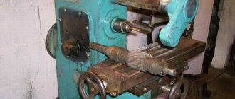
Homemade four-sided machine
It has a number of advantages, including the cost of finished products. The advantages of a homemade four-sided woodworking machine include: the ability to manufacture your own design that meets the task, obtaining the necessary product from wood raw materials.
The principle of operation of a homemade machine in terms of performing technological processes does not differ from factory-made products. Portable design options vary in weight and size.
Compactness allows you to place the equipment of a private user in an unprepared room or garage. Low power consumption without an additional power line ensures stable operation of the machine.
Structurally, four-sided machines are divided into light and heavy series. The former are focused on linear processing of wood, while the latter work with raw materials of large sections.
The technical characteristics of four-sided machines are based on productivity, drive power, feed speed, and material cross-section. The necessary equipment for the line of four-sided machines is selected based on technological functions.
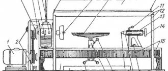
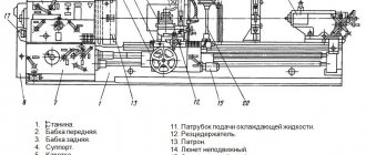
General view of the four-sided longitudinal milling machine S16-42
General view of the four-sided longitudinal milling machine S16-42
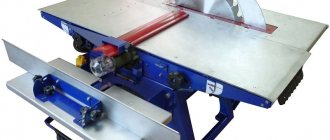
Photo of four-sided planing machine S16-42
Photo of four-sided planing machine S16-42
Photo of four-sided planing machine S16-42
Photo of four-sided planing machine S16-42
Photo of four-sided planing machine S16-42
Photo of four-sided planing machine S16-42
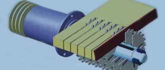
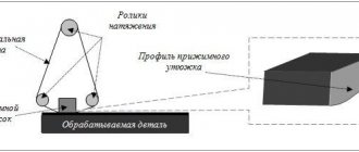
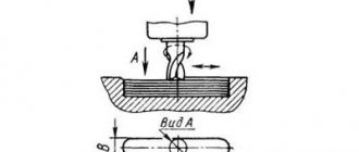
Technological diagram and products produced on a four-sided longitudinal milling machine S16-42
Technological diagram of a four-sided machine
Technological diagram of a four-sided machine
Door frame
Floor board
Location of the main components of the four-sided planer S16-42
Location of the main components of the planing machine S16-42
Location of the main components of the planing machine S16-42
List of components of the jointing machine S16-42:
- 1. Bed S16-42.11.000
- 2. Lower support С16-42.02.000
- 3. Upper caliper C16-42.05.000
- 4. Vertical supports C16-42.03.000 2 pcs.
- 5. Feeding mechanism S16-42.07.000
- 6. Feed drive S16-42.08.000
- 7. Claw protection C16-42.16.000
- 8. Clamp C16-42.19.000
- 9. Side clamp C16-42.20.000
- 10. Front table C16-42.28.000
- 26. Pipeline C16-42.67.000
- 27. Electrical cabinet S16-42.69.000
- X. Spindle S16-42.10.000 1 pc.
Controls for the jointer S16-42:
- 13. Front table height adjustment handle
- 14. Square for adjusting the feed mechanism in height
- 15. Square for moving the movable ruler
- 16. Movable ruler clamp screw
- 17. Height adjustment square
- 18. Clamp squares for vertical movement
- 19. Height adjustment square
- 20. Clamp squares for vertical movement
- 21. Square of spindle axial movement
- 22. Square spindle axial movement clamp
- 23. Square of horizontal movement of the left caliper
- 24. Clamp handle for horizontal movement of the left caliper
- 25. Square of horizontal movement of the right caliper
- 26. Clamp handle for horizontal movement of the right caliper
- 27. Squares of axial movement of spindles
- 28. Left spindle axial movement clamp square
- 29. Right spindle axial movement clamp square
- 30. Voltage switch
Lower caliper
Upper caliper
Vertical supports
Control panel for planing machine S16-42
- 1. Bottom cutter switch S8
- 2. Upper cutter switch S9
- 3. Right cutter switch S10
- 4. Left cutter switch S11
- 5. S21 cutter switch button
- 6. Machine shutdown button S2
- 7. “Forward” feed button S22
- 8. Forward feed cut-off button S24
- 9. “Back” feed button S23
- 10. Machine power switch S1
- 11. Voltage presence signal HL1
- 12.Brake signal HL2
Kinematic diagram of a four-sided longitudinal milling machine S16-42
Kinematic diagram of a four-sided longitudinal milling machine S16-42
Kinematic diagram of a four-sided longitudinal milling machine S16-42
Classification and differences of machines
All four-sided woodworking machines can be divided into:
- thicknesser planer;
- longitudinal milling.
Longitudinal milling machine
used for cutting along the length of the material to the desired size. This woodworking equipment can perform profiling of any complexity. The lower shaft of the knife, taking into account the thickness of the wood being planed, moves together with the tabletop in the vertical direction.
Thicknesser
used to plan a part to a specified thickness on both sides simultaneously. It is initially planing, but has an additional profiling function. Such a device can produce shallow profiling with a simple locking design of a small beam.
Processing wood on four sides simultaneously helps save time, increasing production productivity. That is why four-sided machines are the optimal equipment in the construction and furniture sectors.
Design of the C16-42 longitudinal milling machine, operation of its components
Machine bed
The machine bed is a box-shaped cast iron. All supports, drive, feed mechanism with pressure rollers and front table are installed on the frame. Steel overhead tables and guide rulers along which the workpieces move are attached to the upper plane of the frame. Side clamps and rulers are also installed here.
Front table
The front table is intended for basing workpieces during processing, as well as for setting the amount of allowance for processing with the lower cutter.
Upper horizontal support
Upper support of four-sided longitudinal milling machine S16-42
The upper horizontal support (Fig. 6.) with a cutter installed on it is intended for processing the upper surface of the workpiece.
The spindle 3 is mounted on a movable body 16, which has vertical movement with rolling pins 1 in a plate 12 mounted on the rear wall of the machine bed. Vertical movement of the caliper is made by squares 15 through bevel gears 14 and screw 13, and fixation is made by squares 20 (Fig. 1).
Axial movement of the spindle is made by square 7, fixation by square 2.
The spindle shaft rotates through a flat belt drive 5 from the electric motor. 9. The belt is tensioned using a 10 square.
To reduce the effort to move the caliper in the vertical direction, shock absorbers 11 are used.
A feed mechanism is installed on the upper console part of the rolling pins.
ATTENTION! When axial adjustment of spindles, the spindle sleeve must be cleaned of resins.
PROHIBITED! Use excessive force when tightening the caliper plate terminals and spindle housings. Failure to comply with this requirement leads to failure of the terminal clamps.
Lower horizontal support
The lower horizontal support with a cutter installed on it is designed for processing the lower base face of the workpiece.
The design of the caliper is similar to the upper one, with the exception of the axial movement mechanism and shock absorber.
ATTENTION! The machine is equipped with flat drive belts of one-way directional movement. When replacing them, it is necessary to install the belt so that the direction of movement of the belt, indicated by the arrow on it, corresponds to the direction of rotation of the spindle.
Vertical calipers
Vertical supports for four-sided longitudinal milling machine S16-42
Vertical supports (Fig. 7.) with cutters installed on them are designed for processing the right and left faces of the workpiece. The designs of the left and right calipers are similar.
The spindle 1 is mounted on a movable body 3, which has horizontal movement along rolling pins 2. The horizontal movement of the caliper is carried out by a square 4, fixed by a handle 9.
Axial movement of the spindle is carried out with a square of 8, fixation with a square of 10.
The rotation of the spindle shaft is carried out through a belt drive 7 from the electric motor 6. The belt tension is produced by the square 5.
To base the workpiece, the supports have a left movable 13 and a right fixed 14 strip. When processing narrow workpieces, strip 13 is removed. To do this, it is necessary to lift the springs 11 and remove the bar 13 with screws 12 from the connection with them in the direction from the left caliper. The right bar 14 can be adjusted depending on the diameter of the cutter. To do this, you need to loosen the nuts 15.
ATTENTION! It is necessary to regularly clean the guide elements for both transverse and vertical movement from adhering resins and wood dust. Failure to comply with this requirement leads to “souring” of the guide elements and failure of the caliper adjustment elements.
Feed mechanism
Feed mechanism of a four-sided longitudinal milling machine S16-42
The feed mechanism (Fig. is a dispersed type mechanism.
The feed mechanism is designed to impart translational motion to the workpieces along the machine. It consists of drive modules 2 installed on the traverse 1, connected to each other using splined bushings 3 and a splined shaft 4. A pressure roller 6 is also attached to the traverse. The traverse is a welded frame and is based on two hollow supports of the upper support, so setting up the mechanism feed to the thickness of the workpiece occurs automatically. Sub-adjustment of the feed mechanism when installing a cutter of a different diameter is done with a square 5. The traverse is clamped on the rolling pins using screws 14.
Gear reducers 7 are mounted on the housings of the drive rollers 2, transmitting rotation through cardan transmissions 13 to the lower grooved and smooth 11 rollers. The smooth roller can be adjusted in height above the table level by eccentric bushings located in 12 housings.
The pressing of the upper drive rollers to the workpiece, necessary to ensure the appropriate traction force, is carried out by springs 9, the force of which is adjusted by nuts 10. To adjust the rollers in one plane, nuts 8 are used.
A safety device (claw protection) with a limiter on the thickness of the supplied material is installed on the front end of the traverse to prevent the back ejection of the workpiece.
ATTENTION! Adjusting the feed mechanism to the height of the workpiece should be done as follows: lower the traverse so that when the workpiece passes, the upper feed rollers rise by the size of a tooth and no more.
Failure to comply with this requirement leads to bending of the feed shafts of the upper rollers, the creation of excessive force for pressing the workpiece to the tables and, as a consequence, rapid failure of the feed drive and drive modules!
Operating the machine without complying with this requirement is PROHIBITED!
ATTENTION! When pinching the feed rollers, made with wolf-tooth corrugation, and the clamping elements installed on the feed mechanism, supports and frame, it is possible to stop the workpiece being processed with the feed rollers cutting into the wood. In this case, it is necessary to properly adjust all the clamping elements and, if necessary, move the workpiece back with the cutters turned off.
Drive module
Drive module for four-sided longitudinal milling machine S16-42
The drive module (Fig. 9.) is a combined gearbox consisting of a worm pair 1,2 and a double-row chain drive 3. A chain drive is mounted inside the rockers 4, and rollers 5 are installed on the output shafts. There is a plug 8 on the top of the housing for filling oil, in the lower part there is a drain plug 14. An oil indicator 9 is located on the side of the housing.
ATTENTION! The drive modules are filled with TAD-17I oil. When receiving a new machine, you need to check the oil level and, if necessary, fill it to the level of the center of the eye. After 200 hours of operation, drain the oil and add mineral oil to flush the gearboxes while the machine is idling. After running at idle speed for 1 hour, drain the mineral oil and fill with working oil - TAD-17I to the center of the eye.
ATTENTION! It is necessary to regularly monitor the oil level in the drive modules and, if necessary, top up to the specified level.
After the first 200 hours of operation of the machine, the oil must be changed!
Failure to comply with these requirements leads to premature wear of the worm wheel and failure of the drive module.
Feed drive
The feed drive (Fig. 10) is used to communicate to the feed mechanism two speeds of 7 and 13 m/min.
It consists of an electric motor 1, two-track pulleys 2 and 3, connected to each other by a V-belt 4. The belt is tensioned by nuts 5. To change the feed speed, it is necessary to loosen the belt tension and move it to adjacent tracks. In Fig. 10, the feed mechanism is set to a speed of 13 m/min.
ATTENTION! The spline group of the feed drive must be regularly cleaned to remove wood dust and resins.
Features of work
When using a four-sided wood saw, you must follow the rules specified in the instructions. Parts cannot be processed if their length or thickness exceeds those required by the rules. It is necessary to carry out preventive maintenance in a timely manner to maintain the normal condition of the machine.
The work will have maximum efficiency only if the following operating rules are followed:
Calculate in advance the speed at which the workpiece must move. If this condition is not met, then maximum accuracy cannot be achieved.- Separately deal with the regulation of each block: separately monitor both the milling and planing processes. It should be remembered that the work of these two blocks must be coordinated, otherwise the part will not acquire the desired shape.
- All waste that appears at the work site, especially those generated in the processing area, must be removed in a timely manner.
Machine setup
When adjusting the device to the required thickness, the supports of the upper foot head and upper rollers should be adjusted in height using flywheels. Screws help install the pressure rollers. To adjust the width, side clamps and a vertical spindle are used. You can adjust the machine to the desired profile by installing profile knives on the heads.
Setting up a four-sided machine takes place in six stages:
- Setting the table edge and lower rollers to a thickness that matches the layer of wood being removed.
- Installation of the upper rollers according to the thickness of the workpiece. In this case, there must be a margin for pressure: usually it is made equal to 0.5 cm.
- Installing the front head knives at table level.
- Adjustment of pressure and upper rollers according to the parameters of the workpiece. In the clamps there should be a reserve for clamping - from 1.5 to 2 cm, and in the rollers - 0.5 cm.
- Installing the stop ruler guide at a distance of several millimeters from the vertical head. In this case, a right angle with the lower rollers must be maintained.
- Checking the cutter heads.
Electrical equipment of the machine
General information
The degree of protection of electrical equipment of machine tools is IP54, electric motors are IP44.
The electrical equipment of the machines is designed to be connected to a 3NPE 50Hz, 220/380V network.
Power current collectors are powered from a 50Hz, 220/380V network.
Control circuits 50Hz, 110V.
Lighting and alarm circuits 50Hz, 24V.
The electrical equipment of the machine includes:
- electrical cabinet with an automatic input device, control panel, relay contact and protective equipment;
- electric motors;
- Limit switches;
- lamps;
- additional “Stop” button;
- connecting wires and the sheaths in which they are laid.
The machine is controlled using the following controls:
- input circuit breaker with a combined release for connecting the supply network (installed on the side wall of the electrical cabinet);
- control panel on which control and monitoring equipment is installed.
Protection of power circuits from short circuit currents and overloads is carried out by automatic circuit breakers with combined releases, protection of lighting and alarm control circuits by fuses.
Operating mode selection
To avoid overloading the cutter drive motors during operation, it is necessary to correctly set the amount of allowance to be removed from the workpiece. Its value depends on the feed speed and wood type (see clause 10.4)
For coniferous wood, the maximum amount of allowance removed by one cutter is at a speed of: 7 m/min – 500 sq. mm, 13 m/min – 275 sq. mm.
For example, when processing a board 100 mm wide at a speed of 7 m/min, the thickness of the layer removed should not exceed 5 mm. Allowances for each of the cutters are selected in a similar way.
When processing hard wood, the allowance is reduced by 10...20%.
Durability of cutting tools and quality
The durability of the cutting tool and the quality of product processing depend on the correct installation. Radial runout of cutting edges and end runout of cutters should not exceed 0.05 mm.
When installing cutters, you should pay attention to the correct installation of the knives, the condition of the collet chucks and spacers. Their use with increased runout is not allowed.
Main criteria for selection
Considering that a machine for complex woodworking is expensive equipment, when choosing it it is important to take into account the technical characteristics and all the nuances of the design. Equipment performance depends on:
- speeds and timber feeding systems;
- degree of processing and dimensions.
When choosing the optimal machine model , you should pay attention to:
- workpiece feeding system. It is represented by a set of shafts with a corrugated surface. To minimize the occurrence of defects, system elements must be rubber-coated;
- bed design. Due to the fact that most often such equipment is intended for processing massive products, the frame must withstand maximum loads. The best option would be to choose cast iron;
- accuracy of the operation;
- the complexity of setting up the processing unit. CNC models handle this task best. Milling cutters and planing knives are adjusted automatically. To do this, the machine must be programmed.
In order to accurately position the workpieces relative to the machining center, a sensor system is required. In addition, when analyzing the model, you should take into account the cost of components, the degree of remoteness of the manufacturer’s service centers and warranty conditions.
Setting up the machine for the size of the workpiece
The machine is adjusted to the size of the product being processed using scales, in the order of arrangement of adjustable mechanisms and devices in the feed direction:
- side clamps located on the table are set to the width of the workpiece;
- the front table is set to the amount of allowance removed by the lower cutter on a scale of 31;
- the lower cutter must be installed so that the upper plane of the bed tables is tangent to the circumference of the blade protrusions. To adjust, you need to loosen the squares 18 by 2 turns, move the cutter with the square 17, tighten the squares 18 (hereinafter, see Fig. 1, 2);
- set the upper cutter with a square 19, releasing the squares 20, to the thickness of the workpiece on a scale of 32
- the right cutter is set to the removal value on a scale of 34. To adjust, you need to release the clamp 26 and move the cutter with a square of 25;
- set the movable ruler 15 to the amount of allowance removed by the right cutter, so that the base surface of the ruler is tangent to the circle of the protrusions of the knives for a cylindrical cutter and to the generatrix of the circle of knives located at a smaller diameter for profile cutters. The base surface of the ruler must be parallel to the base ruler 16. Adjustments should be made using a straight edge (beam);
- set the left cutter with a square 23, releasing the clamp 24, to the width of the processed part on a scale of 33. It should be taken into account that the true size of the part will be less by the amount of allowance removed by the right cutter;
- install side rulers 8, 9, 38 so that they securely press the workpiece to the base rulers.
- The machine is configured as delivered to work with cutters with a diameter of 140 mm. When installing cutters of larger diameter on the machine, it is necessary to make additional adjustments: move the feed mechanism 5 with a square 14 so that the plane passing through the generatrix of the feed rollers is 4-5 mm lower than the circumference of the cutting edges of the upper cutter; install clamps 35, 36 2-3 mm below the cutter; install clamp 37 so that it protrudes 2-3 mm from the generatrix of the left cutter.
- the front clamps of the left and upper supports are adjusted so that the noses of the clamping elements rise by 5...7 mm when passing the workpiece; when reconfiguring the machine to a different standard size of workpieces or replacing the cutting tool, make the adjustment again;
Setting up the machine for a narrow workpiece
Remove one rubberized feed roller at a time and install bushings C16-1A.00.028 in their place, remove bar 14 (Fig. 7)
Setting up the machine when installing profile cutters
Move the upper cutter axially with square 21, releasing square 22 by 2 turns. Move the left cutter axially with square 27, sequentially releasing clamp 24 and square 28 by 2 turns. The right cutter is configured in the same way.
Final adjustment of the machine to the size of the workpiece
After setting up, a trial processing of one workpiece is carried out and the obtained dimensions of the processed part are checked for compliance with the specified ones. If necessary, the corresponding calipers are adjusted.
After obtaining the specified dimensions of the workpiece, all adjustable mechanisms and fixtures are carefully secured with screws, nuts and clamping sleeves using the appropriate controls.
Machine adjustment
During the operation of the machine, it becomes necessary to adjust individual components of the machine in order to restore their normal operation:
- The tension of the drive belts of the caliper spindles is done with screw 10 Fig. 6
- The feed drive belt is tensioned using nuts 5, Fig. 10
- tightening the springs of the upper feed rollers
- The pressing force of the lower grooved roller is adjusted by screw 1, Fig. 5
- The pressing force of the feed rollers is adjusted by nuts 10 Fig. 8
- adjustment of the lower smooth roller 11 Fig. 8 in height above the level of the tables is carried out by eccentrics 12 Fig. 8. The roller shape should be 1...1.5 mm above the table level.
"START 4x160"
The size of the product is quickly adjusted using special rulers by moving the right and upper spindles (the left and lower spindles are adjusted within a small range to compensate for tool wear).
The workpieces fed through a powerful gearbox using two pairs of upper and lower, grooved, spaced apart from each other. This solution makes it possible to increase the reliability and accuracy of supply of workpieces of insufficiently good quality and high humidity (unlike the grouse located nearby).
.
The four-sided machine “START 4x160” is equipped with a system of stepless feed speed adjustment , which allows you to optimally adapt to the available material for work.
The exact position of the workpiece in two planes is ensured by special support plates running almost the entire length of the work table and paired spring-loaded rollers. The pressing force of each roller is independently adjustable over a wide range. The paired design of the rollers allows the pressing force to be evenly distributed.
Precise grinding of the working shafts of the four-sided machine “START 4x160” guarantees the complete absence of axial and radial runout of the tool.
High spindle rotation speed (4500 rpm) allows for high quality finishing surfaces. Optionally, it is possible to install an upper spindle with a rotation speed of 6000 rpm.
The four-sided planing machine “START 4x160” is equipped with a system of protection against the back ejection of the workpiece.
The bed is designed in such a way that it provides convenient access to all important components of the machine, while having the necessary rigidity to eliminate vibration during operation.
The working surface of the table is made of especially strong steel, which increases its service life, and is also additionally ground to minimize feed resistance and increase processing accuracy.
The service life of the working surface is at least 10-15 years , however, if necessary, this part can be replaced separately from the rest of the equipment. The replaceable working surface of the table makes the service life of the machine practically unlimited, unlike analogues, where the frame of the machine and its working surface form a single whole.
The electrical systems of the machine are controlled by an independent mobile console.
The machine can be equipped with a special receiving table , with precise height adjustment. Correctly selected height of the receiving table will avoid “undercutting” at the end of the workpiece.
The compact dimensions and light weight of the machine make it quite mobile and easy to install.
The most simplified, but well-thought-out design ensures its high reliability.
Features of disassembly and assembly during repairs
Replacing flat drive belts
ATTENTION! The machine is equipped with flat drive belts of one-way directional movement. When replacing them, it is necessary to install the belt so that the direction of movement of the belt, indicated by the arrow on it, corresponds to the direction of rotation of the spindle.
Replacing flat drive belts on calipers should be carried out taking into account the following recommendations:
For reliable operation of flat belt drives of machine spindle drives during its operation, slippage of belts on pulleys at the time of start-up and during operation is unacceptable.
If the tension weakens and the belt slips, it is necessary to immediately tighten it until the slippage is eliminated.
When replacing a flat drive belt with a new one on spindle drives, you must:
- On a straight section of the belt laid on a flat, flat surface, apply two marks with a marker at a distance of 200 mm along the inner boundaries of the marks.
- Install the belt on the drive pulleys, ensuring a minimum preload so that the branches of the straight sections do not have sagging.
- Measure the actual distance between the internal boundaries of the applied marks.
- Tension the belt until the size between the markers increases by Δ = 2 mm. Start the drive. The belt should not slip during startup.
Advantages and disadvantages of equipment
Machine operation
One of the undoubted positive qualities of operating four-sided woodworking machines is their high productivity. To achieve optimal results, the design must include a numerical control unit.
In this case, the influence of the human factor will be minimal. It is mandatory to fulfill the conditions for the correct preparation of the program, as well as accurate measurements of the workpiece being processed. The optimally equipped four-sided machine is designed for processing square (rectangular) timber or cylindrical workpieces. Milling or jointing of sheet materials can be performed on a maximum of two sides.
The features of operating equipment of this type include the following factors:
- preliminary calculation of the speed of movement of the workpiece along the bed. This is necessary to ensure maximum processing accuracy;
- adjustment of each individual milling or jointing unit, as well as the consistency of their functioning with each other;
- timely removal of production waste from the processing area.
The main disadvantage of four-sided woodworking machines is their high cost, as well as the difficulty of setting up. But in production line conditions, these indicators are not significant.
To automate the work process, the installation must be equipped with an automatic feed line for workpieces. Additionally, this block can perform the function of positioning the part relative to the processing tools.
Technical characteristics of the planing machine S16-42
| Parameter name | S16-42 | S25-5A | S25-4A |
| Basic machine parameters | |||
| Width of processed material (with cutters Ø140), mm | 32..160 | 32..260 | 50..250 |
| Thickness of processed material, mm | 10..100 | 12..160 | 12..230 |
| Smallest dimensions of the processed product (width x thickness) (with cutters Ø140), mm | 30 x 8 | 30 x 10 | 45 x 10 |
| Minimum length of a single workpiece, mm | 400 | 700 | 700 |
| Maximum thickness of the processed material during longitudinal sawing, mm | — | 60 | — |
| The largest allowance when processing with cylindrical cutters (on the 1st spindle), mm | 8 | 7 (8) | 7 |
| Maximum depth of processed profile, mm | 20 | 30 | 30 |
| Number of supports (spindles) | 4 | 5 | 4 |
| Feed speed of workpiece (stepless), m/min | 7..13 | 7..35 | 7..35 |
| Diameters of lower, upper and molding spindles, mm | 40h6 | 50h6 | 50h6 |
| Diameters of right and left spindles, mm | 40h6 | 40h6 | |
| Rotation speed of cutter heads (mills), rpm | 6000 | 5600 | 5600 |
| Electrodynamic spindle braking, direct current | Yes | Yes | Yes |
| Diameter of cylindrical cutters, mm | 140 | 125..140 | 125..140 |
| Diameter of profile cutters on vertical spindles, mm | 180 | 110..200 | 140..203 |
| Diameter of profile cutters on horizontal spindles, mm | 180 | 110..200 | 140..203 |
| The largest diameter of saws installed on the molding support spindle, mm | — | 250 | — |
| Electrical equipment of the machine | |||
| Type of supply current | 380V 50Hz | 380V 50Hz | 380V 50Hz |
| Number of electric motors on the machine, pcs. | 5 | 7 | 7 |
| Electric motor drive bottom, right, left (1,2,3), kW (rpm) | 4,0 (3000) | 7,5 () | 7,5 () |
| Electric motor for driving the upper and molding support (4.5), kW (rpm) | 4,0 (3000) | 11 (3000) | 11 (3000) |
| Feed drive electric motor, kW (rpm) | 1,5 (1000) | 4,0 (750) | 4,0 (750) |
| Electric motor for lifting traverse, kW (rpm) | — | 1,1 (1000) | 1,1 (1000) |
| Installed power: kW | 17,5 | 49,6 | 49,1 |
| Dimensions and weight of the machine | |||
| Machine dimensions (length x width x height), mm | 2455 x 1250 x 1400 | 4770 x 1560 x 1870 | 3150 x 1315 x 1570 |
| Machine weight, kg | 1800 | 5200 | 4200 |
- Four-sided planing machine model C16-42. Operating manual S16-42.00.000 RE,
- Amalitsky V.V. Woodworking machines and tools, 2002
- Afanasyev A.F. Wood carving, Technique, Tools, Products, 2014
- Bobikov P.D. DIY furniture, 2004
- Borisov I.B. Wood processing, 1999
- Jackson A., Day D. Woodworking Bible, 2015
- Golden Book of woodworking for the owner of a country plot, 2015
- Ilyaev M.D. Wood carving, Master's lessons, 2015
- Komarov G.A. Four-sided longitudinal milling machines for wood processing, 1983
- Kondratyev Yu.N., Pitukhin A.V... Technology of wood products, Product design and calculation of materials, 2014
- Korotkov V. I. Woodworking machines, 2007
- Lyavdanskaya O.A., Lyubchich V.A., Bastaeva G.T. Basics of woodworking, 2011
- Lyubchenko V.I. Thicknessing machines for wood processing, 1983
- Manzhos F.M. Wood cutting machines, 1974
- Rasev A.I., Kosarin A.A. Hydrothermal processing and preserving of wood, textbook, 2010
- Ryzhenko V.I. The Complete Encyclopedia of Wood Art, 2010
- Rykunin S.N., Kandalina L.N. Woodworking technology, 2005
- Simonov M.N., Torgovnikov G.I. Debarkers, 1990
- Soloviev A.A., Korotkov V.I. Setting up woodworking equipment, 1987
- Sukhanov V.G. Circular saws for sawing wood, 1984
- Fokin S.V., Shportko O.N. Woodworking, Technologies and equipment, 2017
- Hilton Bill Woodworking, The Complete Guide to Stylish Home Furniture Making, 2017
Bibliography:
Related Links. Additional Information
- Directory of woodworking machines
- Directory of manufacturers of woodworking machines and equipment
- Directory of manufacturers of household woodworking machines
- Directory of chipper manufacturers
- Classification of woodworking machines
- Machines for longitudinal cutting of lumber
- Sawmill frames. Classification
- Lumber. Basic concepts. Terms and Definitions
Home About the company News Articles Price list Contacts Reference information Interesting video KPO woodworking machines Manufacturers
Purchase of a machine
Longitudinal milling machine
can be purchased at specialized construction stores, but it is better to buy it directly from the manufacturer (if we are talking about domestic manufacturers). You can rent equipment or purchase it in installments.
Before purchasing equipment, you need to pay attention to the following main points:
- performance;
- accuracy;
- reliability of operation;
- availability of service;
- equipment price.
If a four-sided wood saw will be an addition to an existing line, it is important to consider its dimensions. During the purchase, it is necessary to take into account the technical parameters and the combination of various processing options, the weight of the equipment and the speed of work.
Some companies providing such equipment are still little known. The price of their products is relatively low, and the quality is adequate
. For example, the German brand Beaver. The cost of their products is low due to the fact that production is located in Taiwan and China. But parts of the assembly are made in Germany.
When choosing equipment, you should not consider cheap Chinese-made models. Please note that it will be very difficult to find spare parts for them.